The stable current generator (GCT) in question is well suited for charging batteries (up to 12 V). The charging current can be set within 0...10 A.
However, this GTS was manufactured not so much for charging batteries, but for other purposes. Powerful GTS allows you to quickly evaluate almost any contact connections based on the value of transition resistance (relay contacts, switches, etc.).
About measuring small resistance values (milliohmmeter mode)
You will need a millivoltmeter with a limit of 200 or 2000 mV. Resistor R9 (Fig. 1) sets the current through the measured resistance (Rн) to 1 A. Now for every millivolt of voltage drop across the resistance Rн there corresponds a milliohm of this resistance. When higher accuracy of measurement of Rн is required, switch to the 10 A sub-range (switch SA2 is pressed) and set the current through Rн to 10 A. Now each milliohm of resistance corresponds to 10 mV.
With such a current value (10 A), almost any detachable connection “rings” perfectly. Depending on the transition resistance, it “settles” on them, from a few millivolts (excellent quality contact) to tens and hundreds of millivolts (these are already defective contacts).
Measuring small resistances at a current >10 A allows you to quickly identify many defects that are hidden for testing with multimeters. Exclusive inspection (in numbers!) of almost any installation wires is provided. Take a piece of installation wire several tens of centimeters long and connect it to the GTS.
The voltage drop across it determines its suitability for certain purposes. As long as a person is dealing with structures where the current value does not exceed 1...3 A, then he does not need to measure milliohms. But in designs with currents greater than 10 A, a lot changes. “Chinese” wires (a thick layer of insulation with a small cross-section of copper conductors) began to appear on the markets.
Domestic wires of the same diameter (in terms of insulation) have a linear resistance that is two or more times less than “Chinese” ones. To prevent the millivoltmeter from being damaged when Rн is turned off, during the measurement the device’s terminals are shunted with a KD2998 diode (any other one with a current >10 A will do), as shown in Fig. 1.
GTS is of particular value when checking used detachable connections and relay contacts. Contacts that require cleaning or replacement are immediately identified. Here are just a few examples. Widespread toggle switches of types TV, TP, MT, PT, etc. Over time, their transition resistance increases from 3...5 mOhm to 0.1...0.5 Ohm and even more!
It makes sense to put appropriate inscriptions on the switch body, which should determine the purpose (application) of the switch. Often cleaning the relay contacts gave a good result: usually the contact resistance decreases by 2-10 times (depending on the wear of the contacts). A reduction in contact resistance was also achieved by optimal contact clamping. Remember that poor contact causes accelerated destruction of the contacting surfaces.
About painful things. People buy regular mains (220 V) plugs, sockets and switches, which overheat when the load is more than 1 kW. Although encouraging 6 A is written on the housings of these products, the inscriptions do not guarantee the proper quality of the connections.
You can, of course, check such products by connecting them for 30...60 minutes with a load of 1 kW (anticipating possible heating in the defective connection). And you can use GTS to measure contact resistance. The question is very relevant, because poor contacts in a 220 V electrical load often lead to a fire.
And the quality of modern household power plugs, sockets and switches is only decreasing (saving materials, poor assembly, lack of reliable spring contacts).
About GTS circuitry
The GST is made on op-amp DA1 and a powerful field-effect transistor VT7, which provides the required current in the load. Since at direct current (our case) the field-effect transistor does not consume current through the gate circuit, the op-amp operates virtually without load, which increases the reliability of the entire GTS.
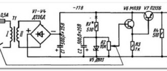
Rice. 1. Schematic diagram of a current stabilizer for charging batteries and powering devices.
| R1 - 100 Ohm | C1 - 0.47 µF x 630 V |
| R2 - 300 Ohm | C2 - 0.47 µF x 160 V |
| R3, R4 - 120 Ohm | C3 - 100 uF x 25 V |
| R5 - 13 Ohm | C4 - 0.1 µF |
| R6 - 1.5 kOhm | C5 - 4700 pF |
| R7 - 39 kOhm* | C6 - 100 uF x 25 V |
| R8 - 8 kOhm* | C7 - 0.1 µF |
| R9 - 1 kOhm | C8, C9, C10 - 4000 uF x 25 V |
| R10 - 100 kOhm | C11, C12 - 200 uF x 50 V |
| R11 - 1 kOhm | C13 - 4700 pF |
| R12 - 13 Ohm | |
| R13 - 1 kOhm | VD1…VD4 - KD2998G |
| R14, R15 - 1 kOhm | VD5 - KTs405V |
| R16 - 0.1 Ohm | VD6 - AL307 |
| R17 - 9.2 kOhm* | VD7, VD8 - D814D |
| R18 - 800 Ohm* | VD9 - D818E |
| R19 - 330 Ohm | VD10 - KD2998G |
| R20 - 3.3 kOhm | |
| R21, R22 - 30 Ohm | VT1, VT2 - KT502D VT3, VT4 - KT503D |
| DA1 - KR140UD708 | VT5 - KT815D VT6 - KT814G |
| PA1 - M4204-100 µA PV1 - M903/4-15 V T1 - TS-180-2 | VT7 - IRFZ48N SA1, SA2 - TP1-2 |
The op-amp controls the conductivity of the field-effect transistor, which determines the current in the load Rh.
The GTS has two current control subranges. In the position of switch SA2 shown in the diagram, we have 0...2 A. The second sub-range is up to 10 A.
The current sensor (resistor R16) is used both for the GTS circuit and as an ammeter shunt. The reference voltage source is assembled on a precision Zener diode VD9 type D818E and a current generator, which, in turn, is assembled on transistors VT1-VT4 (borrowed from [3]).
This scheme has been undeservedly forgotten by radio amateurs. It has greater parameter stability than single-transistor GTS circuits. The stability of the GTS output current in the Rh circuit is almost completely determined by the stability of the voltage at the non-inverting input of the op-amp, i.e. ION stability.
The stability of ammeter readings PA1 depends on the stability of elements R16-R18.
Details
Instead of the KR140UD708 OU, K140UD7 was also installed. Field effect transistor IRFZ46 (KP741A, B), IRFZ44 (KP723A), IRFZ45 (KP723B), IRFZ40 (KP723V), IRF540 (KP746A), IRF541 (KP746B), IRF542 (KP746V), IRFP150 (KP747A), etc.
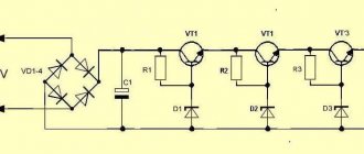
The field-effect transistor was chosen for reasons of maximum reliability and simplicity of design. If there is no field-effect transistor, it can be replaced with two transistors, as shown in Fig. 2. However, the KT827A transistor here operates in modes close to the limit (when the load current is 10 A).
It is beneficial to replace the KT827A with two transistors. This is what radio amateurs did, repeating the GTS circuit (Fig. 1) and not having field-effect transistors (Fig. 3).
The VT7 transistor must be equipped with a good heat sink with a surface area of at least 2000 cm2. Transistors VT1, VT2 types KT3107, KT361 with any letter indices. Transistors VT3, VT4 types KT3102, KT315 with any letter indices. KT502, KT503 are also suitable here. Transistor VT5 type KT815, KT817; transistor VT6 type KT814, KT816.
Rice. 2. Circuit for replacing a powerful field-effect transistor with two silicon ones.
Rice. 3. Powerful replacement of a field-effect transistor with three silicon ones.
About rectifier diodes. Any powerful diodes with a current of more than 10 A will do. If powerful diodes still cannot be purchased (it is simply unrealistic to buy them on the periphery), then use the old and time-tested scheme (Fig. 4) of operating two diode bridges for one common load (parallel mode).
The circuit in Fig. 5 has the same purpose as the circuit in Fig. 4, but the resistors are included in such a way that all 8 diodes are placed on three radiators, just like the diodes of a conventional bridge. However, here the number of resistors is already 8 (instead of 4 in Fig. 4).
For the circuit in Fig. 1, the resistances of resistors R1-R4 (Fig. 4) and R1-R8 (Fig. 5) should not exceed 0.1 Ohm (their range is 0.03...0.1 Ohm, but they should be the same).
In the circuit of Fig. 4, bridges KTs402, KTs405 (R1-R4 are equal to 0.5 ... 1 Ohm) and other diodes (for KTs402, 405 the sum of currents does not exceed 2 A) are also used.
Rice. 4. Rectifier on diode bridges.
Rice. 5. Diode rectifier.
Wirewound resistors were made from non-scarce nichrome wire with a diameter of more than 1.5 mm. There will be no complaints about the stability of resistor R16 if it is done properly (at a current of 10 A, it dissipates 10 W of power). According to TCS, nichrome is 30 times worse than constantan, 3 times worse than manganin, but 26 times more stable than copper.
To catch up with manganin in terms of stability, you need to reduce the temperature (power on the resistor). 4 nichrome resistors connected in parallel solve this problem. After all, manganin or constantan shunts are in short supply in the periphery. In addition, the maximum operating temperature of manganin is less than 100°C, while that of nichrome is -900°C.
Shunts prepared in the above manner will be practically “eternal” (2.5 W of power on each will not cause much heating). Resistors R7, R8 and R17, R18 are made up of resistors of type C2-13, since the stability of their resistance determines the stability of the GTS output current and, accordingly, the ammeter readings. All other resistors are MLT type, except wirewound R9 type PP2-12.
Electrolytic capacitors C8-C10 are widely available, such as K50-35 or K50-6. It is impossible to reduce their total capacity, since ripples will penetrate into the load and errors will appear in the operation of the GTS (at a current value close to 10 A). In addition, the insufficient capacity of the rectifier will not allow obtaining an output current of 10 A (at the indicated value of the alternating voltage of winding II of the network transformer).
If the GTS will not be used as a charger for 12-volt batteries, then the voltage of winding II should be reduced.
Rice. 6. Diagram of a full-wave rectifier with a midpoint.
You can check diodes and various contact connections even when the voltage of winding II is several volts. In practice, this voltage was reduced to 6 V (with a load of 10 A).
The basic version of this GTS contained a transformer, winding II of which, at a current of 10 A, should give at least 10.25 V. Winding II was made with a tap when it was necessary to obtain a current of more than 10 A in milliohmmeter mode, preserving the GTS as a charger for 12- volt batteries.
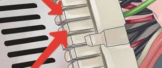
A little “know-how” is that it is better to check powerful contact (plug-in) connections at a current significantly higher than the rated value. For example, the plug indicates 6 A, which means that the reliability of the connection must be checked at a current of 10...20 A.
In this case, a substandard detachable connection immediately reveals itself. And a lot of such new substandard plugs, sockets and switches have appeared on the market!
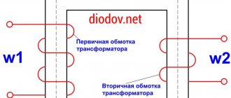
About transformer T1. The first (basic) version of the GTS was assembled on a fairly small-sized transformer with a power of only 160 VA. The inscription on it: “TBS3-0.16U3 R160 VA 50-60 Hz. GOST.5.1360-72". It uses SL-iron.
It is smaller in volume than the TS-180 and operates silently, which cannot be said about the TS-180. The secondary windings are re-wound. Winding II contains 45 turns of PEV-1.4 mm in two wires.
Open circuit voltage is 11.5 V. Under a load of 10 A, the output voltage is at least 10.25 V, but if Schottky diodes are installed in the diode bridge (KD2998, 2991).
For silicon D242, 243, the voltage in winding II was increased by 2.5 V. If the diodes in the circuits of Fig. 4 and Fig. 5 are matched in pairs, then resistors R1-R4 (Fig. 4) and R1-R8 (Fig. 5) can be removed (short-circuited). In practice, this was done only with parallel diodes having a spread in Upr of no more than 5%. Winding III T1 contains 78 turns of double wire PELSHO-0.41. The tap from winding II for a current of 20 A (not shown in the diagram) was made from the 28th turn.
You can also use the TS-180-2 transformer. Windings 9-10 and 9′-10′ were connected in series. According to the specifications, they have 6.4 V and a load current of 4.7 A. They contain 23 turns of 01.55 mm wire. They cannot be operated at a current of 10 A, but they can be used for a short time.
Windings 5-6, 5′-6′ and 11-12, 11′-12′ were used as winding III, connecting them in series (5-6 with winding 11-12 and 5′-6′ with winding 11′-12 ′). Windings 11-12 provide 6.4 V each, only 11′-12′ are designed for a current of 0.3 A, and 11-12 for 1.5 A. At a current of 10 A, the “hottest” windings 9-10 ( within a few minutes), but since they are located in the very top layer, their cooling is the best. For additional heat removal, the outer layer of paper (along with the label) was removed on each TC-180 reel.
When the GTS was manufactured only for continuity of low-resistance connections, the bridge rectifier was replaced with a full-wave circuit with a midpoint (Fig. 6). Here, as in the diagrams Fig. 4 and Fig. 5, 2 pieces were installed. D242A in parallel. All diodes here require one radiator.
The main thing in this situation (in relation to the TS-180) is that now the rated current from the windings is no longer 4.7 A, but more than 7 A. According to [4], we have a current gain of 1.4 times relative to one winding 9-10.
What does a power supply do?
First you need to understand the purpose of the power source. • It must convert the alternating current received from the AC power supply into direct current. • It should output a user-selectable voltage ranging from 2V to 25V.
Main advantages:
• Inexpensive. • Simple and easy to use. • Versatile.
List of required components
1. Step-down transformer 2 A (from 220 V to 24 V). 2. Voltage regulator lm317 IC with heat exchanger radiator. 3. Capacitors (polarized): 2200 microfarads 50 V; 100 microfarad 50 V; 1 microfarad 50 V. (note: the voltage rating of the capacitors must be higher than the voltage applied to their contacts). 4. Capacitor (non-polarized): 0.1 microfarad. 5. Potentiometer 10 kOhm. 6. Resistance 1 kOhm. 7. Voltmeter with LCD display. 8. 2.5 A fuse. 9. Screw terminals. 10. Connecting wire with plug. 11. Diodes 1n5822. 12. Circuit board.
Drawing up an electrical diagram
• In the upper part of the figure, the transformer is connected to the AC power supply. It reduces the voltage to 24 V, but the current remains alternating with a frequency of 50 Hz. • The lower half of the figure shows the connection of four diodes into a rectifier bridge. 1n5822 diodes allow current to pass when forward biased, and block current to flow when reverse biased. As a result, the DC output voltage pulsates at a frequency of 100 Hz.
• In this figure, a 2200 microfarad capacitor has been added to filter the output current and provide a stable voltage of 24 VDC. • At this point, a fuse can be connected in series with the circuit to ensure its protection. • So we have: 1. Step down AC transformer to 24V. 2. AC to pulsating DC converter with voltage up to 24V. 3. Filtered current to produce clean and stable 24V voltage. • All this will be connected to lm317 voltage regulator circuit described below
Introduction to Lm317
• Now our task is to control the output voltage, changing it according to our needs. For this we use a voltage regulator lm317. • Lm317 as shown in the picture has 3 pins. These are an adjustment pin (pin1 - ADJUST), an output pin (pin2 - OUNPUT), and an input pin (pin3 - INPUT). • The lm317 controller generates heat during operation, so it requires a heat exchanger heat sink • The heat exchanger heat sink is a metal plate connected to an integrated circuit to dissipate the heat it generates into the surrounding area.
A small retreat
The enamel wire is now truly gold-plated: for 1 kg you need to pay up to 5 USD. For this money you can actually buy 2-4 pieces. transformers TS-180, in which the wires are no less.
All other versions of the GTS were carried out mainly on a more powerful basis (rewinded T S-270-1 or toroidal transformers), i.e. the secondary windings were re-wound. If enamel wire is not available, then you can use almost any single-, stranded copper or aluminum wire. The main thing is that the required cross-section is obtained.
The guideline is simple - a copper core with a diameter of 2 mm for a current of no more than 10 A. Information on network transformers is very useful [5].
About wirewound resistors (except R16). All of them can be copper, i.e. in practice, pieces of copper wire 00.4...0.6 mm were used. The latter with a length of 1 m gives a resistance of 0.058 Ohm, with a length of 120 cm - 0.07 Ohm. The passage of current (due to the TCR of copper) causes an increase in resistance to 0.092 Ohms.
Thus, a piece of enamel wire 00.6 mm long and 50.100 cm long is more than enough for these rectifier circuits. The length of the segment should not be confusing, since the wire can easily be placed on a frame with a diameter of more than 1 cm.
In the circuit of Fig. 6, it is advantageous to use “tablets” - KD213, KD2997, 2999. It is convenient to place two “tablets” on one radiator specifically for cases such as KD213. Wherever possible (in terms of voltage), it makes sense to use diodes with a Schottky barrier.
When purchasing KD2998, be sure to check it for the value of Rrev.
Remember that overheating is the death of all radio components. With increasing temperature, pn junctions degrade and the number of failures increases. There is no need to focus on the manufacturer, whose main task is to minimize the consumption of materials and components, but you need to create a margin of reliability and strength yourself, where possible.
DC power supplies
Direct current is a current that almost (since nothing is ideal in the world) does not change over time, neither in magnitude nor in direction. Historically, the first DC sources were exclusively chemical. At first they were represented only by galvanic cells, and later batteries appeared.
Galvanic cells and batteries have a strictly defined polarity, and the direction of the current in them does not spontaneously change, therefore chemical current sources are fundamentally direct current sources.
Galvanic cell
The AA AA battery is a prime example of a modern galvanic cell. A cylindrical alkaline battery (which people like to call alkaline, while the word "alkaline" is translated as "alkaline") contains a solution of potassium hydroxide as an electrolyte. The positive terminal of the battery contains manganese dioxide, and the negative terminal contains zinc powder.
When the external circuit of the battery is closed to the load, a chemical reaction of zinc oxidation occurs at the anode (negative pole), and at the same time, at the cathode (positive pole), a reduction reaction of manganese tetravalent oxide to manganese trivalent oxide occurs.
As a result, electrons flow from the negative pole towards the positive pole through the external load circuit. This is how a direct current source—a galvanic cell—works.
The chemical process in a galvanic cell is not reversible, that is, trying to charge it is useless. The voltage between the poles of a new AA battery is 1.5 volts, which is determined by the potentials of the substances involved in the chemical reaction inside it.
Battery
A lithium-ion battery, unlike a battery, can be recharged after being discharged because its chemical process is reversible. In appearance, the battery works like a battery, that is, it also supplies only direct current to the load circuit, but the capacity of the battery is usually greater than that of a battery of approximately the same size.
As a lithium battery discharges, a chemical reaction at the anode (negative electrode) separates the lithium from the carbon and converts it into a salt at the cathode (positive electrode). And when charging, lithium ions again move to carbon at the anode.
The potential difference between the poles of a lithium-ion battery can reach up to 4.2 volts. The maximum current depends on the area of interaction of the electrodes inside the battery with the electrolyte and, accordingly, with each other.
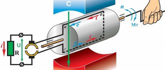
Generator
On an industrial scale, direct current is obtained using direct current generators. As a rule, on the stator of such a machine there are stationary magnets or electromagnets that induce EMF in the rotating circuits according to the law of electromagnetic induction.
The rotating circuits are each connected to the contact plates of the brush-commutator assembly, through which the generated current is removed into the load circuit through fixed brushes. Since the circuits contact the positive and negative brushes only when passing by certain magnetic poles of the stator, the current in the external circuit is rectified alternating, that is, pulsating direct.
The magnitude of the current depends on the cross-section of the wires, the induction of the stator magnetic field and the stator area. The voltage value depends on the rotation speed of the generator rotor and on the induction of the stator magnetic field.
Solar cell
Solar panels also provide direct current. Photons of sunlight hitting the photocell cause the movement of positively charged holes and negatively charged electrons through the pn junction, and thus a direct current is obtained in the external circuit.
The larger the total area of photocells, the more electrons and holes participate in the generation of current, the greater the current that can be obtained from the solar battery. The generated voltage of a solar cell depends on the intensity of sunlight and on the number of photocells connected in series that are part of the solar cell design.
Transformer with rectifier
Previously, in electronic equipment to obtain direct current, when powered from a household alternating current network, power supplies with transformers on iron were often used. The alternating mains voltage was stepped down using a transformer and then rectified using a tube or diode rectifier.
After the rectifier in such a circuit there is always a filter consisting of at least a capacitor, and at best - a capacitor and a choke, and even a transistor voltage stabilizer, especially if the current source must be adjustable.
The voltage at the output of such a power supply depends on the number of turns of the secondary winding of the transformer, and the maximum current value depends on the rated power of the transformer.
Impulse power block
Today, in electronic equipment, power supplies with low-frequency transformers on iron are almost never used to produce direct current; they have been replaced by switching power supplies. In them, the rectified mains voltage is first lowered using a high-frequency transformer and transistor switches, and then rectified. The current is directed through the filter into the filter capacitor.
The design of a switching power supply is much smaller in size than with a transformer on iron. But there is more noise in the output current. Therefore, when designing switching power supplies, special attention is paid to filtering the current at the output to the load.
The voltage at the output of a switching power supply depends on the design of the electronic circuit, and the maximum current depends on the size of the high-frequency transformer and the quality of the electronic components located on the circuit.
Capacitor and ionistor
In a certain sense, an electric capacitor can be called a source of direct electric current. A capacitor stores electrical energy in the form of a constant electric field between its plates, and can then release this energy in the form of direct current or pulsed discharge. Both are essentially direct current, differing only in the duration of manifestation.
But electrolytic capacitors today are produced with huge capacities of thousands or more microfarads. A special type of capacitor is an ionistor (supercapacitor) - it occupies an intermediate position between a battery and a capacitor.
Chemical processes in the ionistor proceed at almost the same speed as in a capacitor, but unlike a battery, the ionistor has less internal resistance, which allows it to receive higher direct currents from the ionistors over a longer period of time. The larger the capacitance of the capacitor, the larger and longer the current can be obtained with its help.
Source