Principle of operation
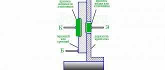
The operating principle of this device is based on the features of the pn junction. Near the junctions of two semiconductors there is a layer in which there are no charge carriers. This is the barrier layer. His resistance is great.
When a layer is exposed to a certain external alternating voltage, its thickness becomes smaller and subsequently disappears altogether. The current that increases is called forward current. It runs from the anode to the cathode. If the external alternating voltage has a different polarity, the blocking layer will be larger and the resistance will increase.
Rectifier diode - types, principle of operation and application
There are many devices created for the purpose of converting electric current, and rectifying diodes are one of them.
Rectifier diode – converter of alternating current into direct current. It is a type of semiconductor. It is widely used due to its main characteristic – the transfer of electric current strictly in one direction.
Operating principle
The necessary effect during operation of the device is created by the features of the pn junction. They consist in the fact that a layer is built near the junction of two semiconductors, which is characterized by two points: high resistance and the absence of charge carriers.
Further, when this barrier layer is exposed to alternating voltage from the outside, its thickness decreases and subsequently disappears. The current that increases during this is the direct current that passes from the anode to the cathode.
If the polarity of the external alternating voltage changes, the blocking layer will be larger and the resistance will inevitably increase.
The current-voltage characteristic of the rectifier diode (volt-ampere characteristic) also gives an idea of the specifics of the rectifier’s operation and is nonlinear. It looks like this: there are two branches - forward and reverse. The first reflects the highest conductivity of the semiconductor when a direct potential difference occurs. The second indicates the value of low conductivity at an inverse potential difference.
The current-voltage characteristics of the rectifier are directly proportional to the temperature, with an increase in which the potential difference decreases. Electric current will not pass through the device in the case of low conductivity, but an avalanche breakdown occurs if the reverse voltage increases to a certain level.
Using an assembly
When operating a semiconductor diode rectifier, only half of the alternating current waves are useful, and more than half of the input voltage is therefore irretrievably lost.
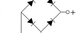
In order to improve the quality of conversion of alternating current to direct current, an assembly of four devices is used - a diode bridge. It differs favorably in that it passes current during each half-cycle. Diode bridges are produced in the form of a kit enclosed in a plastic case.
Schematic diagram of a diode bridge
Physical and technical parameters
The main parameters of rectifier diodes are based on the following values:
- the maximum permissible value of the potential difference when rectifying the current, at which the device will not fail;
- the highest average rectified current;
- the highest reverse voltage value.
The industry produces rectifiers with different physical characteristics. Accordingly, the devices have different shapes and installation methods. They are divided into three groups:
- High power rectifier diodes. They are characterized by a current capacity of up to 400 A and are high-voltage. High-voltage rectifier diodes are produced in two types of packages - pin, where the case is sealed and glass, and tablet, where the case is made of ceramic.
- Medium power rectifier diodes. They have a capacity from 300 mA to 10A.
- Low power rectifier diodes. The maximum permissible current value is up to 300 mA.
Selection of rectifier diodes
When purchasing a device, you must be guided by the following parameters:
- values of the current-voltage characteristic of the maximum reverse and peak current;
- maximum permissible reverse and forward voltage;
- average rectified current strength;
- device material and type of installation.
Depending on the physical characteristics, a corresponding designation is applied to the device body. A catalog with markings of rectifier diodes is presented in a specialized reference book. You need to know that the labeling of imported analogues differs from domestic ones.
It is also worth paying attention to the fact that rectifier circuits differ in the number of phases:
- Single-phase. Widely used for household electrical appliances. There are diodes for automobiles and for electric arc welding.
- Multiphase. Indispensable for industrial equipment, public and special transport.
Schottky diode
A special position is occupied by the Schottky diode. It was invented in connection with the growing needs in the developing radio electronics industry. Its main difference from other diodes is that its design includes a metal-semiconductor as an alternative to a pn junction. Accordingly, the Schottky diode has its own unique properties that silicon rectifier diodes cannot boast of. Some of them:
- operational renewability of the charge due to its low value;
- minimum voltage drop across the junction when connected directly;
- The leakage current is significant.
When making a Schottky diode, materials such as silicon and gallium arsenide are used, but germanium is also sometimes used. The properties of the materials are slightly different, but in any case, the maximum permissible reverse voltage for a Schottky rectifier is no more than 1200 V.
In contrast to all the advantages, the design of this type also has disadvantages. For example, in a bridge assembly, the device categorically does not perceive excess reverse current. Violation of the condition leads to breakdown of the rectifier. Also, a small voltage drop occurs at a low voltage of about 60-70 V. If the value exceeds this indicator, then the device turns into an ordinary rectifier.
Types of devices, their designation
By design, there are two types of devices: point and planar. In industry, the most common are silicon (designation: Si) and germanium (designation: Ge). The former have a higher operating temperature. The advantage of the latter is the low voltage drop with forward current.
The designation principle for diodes is an alphanumeric code:
- The first element is the designation of the material from which it is made,
- The second defines a subclass,
- The third denotes working capabilities,
- The fourth is the development serial number,
- Fifth – designation of sorting according to parameters.
Volt-ampere characteristics
The current-voltage characteristic (volt-ampere characteristic) of a rectifying diode can be represented graphically. The graph shows that the current-voltage characteristic of the device is nonlinear.
In the initial quadrant of the current-voltage characteristic, its direct branch reflects the highest conductivity of the device when a direct potential difference is applied to it. The reverse branch (third quadrant) of the current-voltage characteristic reflects the situation of low conductivity. This occurs when the potential difference is reversed.
Actual current-voltage characteristics are dependent on temperature. As the temperature increases, the direct potential difference decreases.
From the graph of the current-voltage characteristic it follows that with low conductivity, current does not pass through the device. However, at a certain value of the reverse voltage, an avalanche breakdown occurs.
The current-voltage characteristic of silicon devices differs from germanium devices. The current-voltage characteristics are given depending on different ambient temperatures. The reverse current of silicon devices is much less than that of germanium devices. From the graphs of the current-voltage characteristic it follows that it increases with increasing temperature.
The most important property is the sharp asymmetry of the current-voltage characteristic. With forward bias - high conductivity, with reverse bias - low. It is this property that is used in rectifying devices.
Design options
Design options for diodes are presented in Figure 2.3, Table 2.1.
Table 2.1 – Table of characteristics of the BAS70 rectifier diode
| Parameter | Meaning | |
| Type of shell | SOT23-3 | |
| Limit direct direct current, mA | 200 | |
| Limit forward current, amplitude value, mA | 300 | |
| Limit reverse voltage, V | 70 | |
| Operating temperature range, ºС | -55 … +150 |
Rectification factor
Analyzing the device characteristics, it should be noted: such quantities as the rectification coefficient, resistance, and capacitance of the device are taken into account. These are differential parameters.
It reflects the quality of the rectifier.
It can be calculated: it will be equal to the ratio of the forward current of the device to the reverse one. This calculation is acceptable for an ideal device. The value of the rectification coefficient can reach several hundred thousand. The larger it is, the better the straightener does its job.
Basic device parameters
What parameters characterize the devices? Main parameters of rectifier diodes:
- The highest value of the average forward current,
- The highest permissible reverse voltage value,
- The maximum permissible frequency of the potential difference at a given forward current.
Based on the maximum forward current value, rectifier diodes are divided into:
- Low power devices. They have a forward current value of up to 300 mA,
- Medium power rectifier diodes. Forward current change range from 300 mA to 10 A,
- Power (high power). Value more than 10 A.
There are power devices that depend on the shape, material, and type of installation. The most common ones are:
- Medium power power devices. Their technical parameters allow working with voltages up to 1.3 kiloVolt,
- Power, high power, capable of passing current up to 400 A. These are high-voltage devices. There are different housings for power diodes. The most common are pin and tablet types.
Application of diodes
One should not think that diodes are used only as rectifiers and detectors. In addition, you can highlight many more of their professions. The current-voltage characteristics of diodes allow their use where nonlinear processing of analog signals is required. These are frequency converters, logarithmic amplifiers, detectors and other devices. Diodes in such devices are used either directly as a converter or form the characteristics of the device when included in the feedback circuit. Diodes are widely used in stabilized power supplies, as reference voltage sources (zener diodes), or as switching elements of storage inductors (pulse voltage stabilizers).
Rectifier diodes.
Using diodes it is very easy to create signal limiters: two diodes connected back-to-back - in parallel serve as excellent protection for the input of an amplifier, for example, a microphone, from supplying an increased signal level. In addition to the listed devices, diodes are very often used in signal switches, as well as in logic devices. It is enough to recall the logical operations AND, OR and their combinations. One type of diode is LED. Once upon a time they were used only as indicators in various devices. Now they are everywhere, from the simplest flashlights to TVs with LED backlighting, it is simply impossible not to notice them.
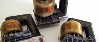
Diode parameters
Diodes have a lot of parameters and they are determined by the function they perform in a particular device. For example, in diodes that generate microwave oscillations, a very important parameter is the operating frequency, as well as the cutoff frequency at which the generation fails. But for rectifier diodes this parameter is completely unimportant. The main parameters of rectifier diodes are shown in the table below.
Table of main parameters of rectifier diodes.
In switching and switching diodes, the switching speed and recovery time, that is, the speed of full opening and full closing, are important. In high-power power diodes, power dissipation is important. To do this, they are mounted on special radiators. But diodes operating in low-current devices do not need any radiators. But there are parameters that are considered important for all types of diodes, we list them:
- U pr. – permissible voltage on the diode when current flows through it in the forward direction. You should not exceed this voltage, as this will lead to its damage.
- U rev. – permissible voltage on the diode in the closed state. It is also called breakdown voltage. In the closed state, when no current flows through the pn junction, a reverse voltage is formed at the terminals. If it exceeds the permissible value, this will lead to a physical “breakdown” of the pn junction. As a result, the diode will turn into an ordinary conductor (burn out).
Schottky diodes are very sensitive to excess reverse voltage, which very often fail for this reason.
Conventional diodes, for example, silicon rectifiers, are more resistant to excess reverse voltage. When it is slightly exceeded, they go into a reversible breakdown mode. If the diode crystal does not have time to overheat due to excessive heat generation, then the product can work for a long time.
- I ave. – direct current of the diode. This is a very important parameter that should be taken into account when replacing diodes with analogues or when designing homemade devices. The magnitude of the forward current for different modifications can reach tens and hundreds of amperes. Particularly powerful diodes are installed on the radiator to remove heat, which is formed due to the thermal effect of the current. The PN junction in direct connection also has low resistance. At small operating currents its effect is not noticeable, but at currents of a few to tens of amperes the diode crystal heats up noticeably. For example, a rectifier diode bridge in an inverter welding machine must be installed on a radiator.
- I return – reverse current of the diode. The reverse current is the so-called minority carrier current. It is formed when the diode is closed. The amount of reverse current is very small and in the vast majority of cases it is not taken into account.
- U stabilization – stabilization voltage (for zener diodes). Read more about this parameter in the article about zener diode.
We advise you to study Choosing a cable for connecting an electric stove
In addition, it should be borne in mind that all these parameters in the technical literature are printed with the “max” symbol. The maximum permissible value of this parameter is indicated here. Therefore, when choosing the type of diode for your design, you must count on the maximum permissible values.
High current diodes.
Rectifier circuits
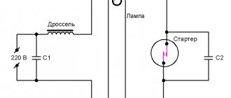
The circuits for connecting power devices are different. To rectify the mains voltage, they are divided into single-phase and multiphase, half-wave and full-wave. Most of them are single phase. Below is the design of such a half-wave rectifier and two voltage graphs on a timing diagram.
Alternating voltage U1 is supplied to the input (Fig. a). On the right side of the graph it is represented by a sine wave. The diode state is open. Current flows through the load Rн. During the negative half-cycle the diode is closed. Therefore, only a positive potential difference is supplied to the load. In Fig. its time dependence is reflected. This potential difference operates during one half-cycle. This is where the name of the scheme comes from.
The simplest full-wave circuit consists of two half-wave circuits. For this rectification design, two diodes and one resistor are sufficient.
Diodes only allow positive AC current to pass through. The disadvantage of the design is that during the half-cycle the alternating potential difference is removed only from half of the secondary winding of the transformer.
If you use four diodes in the design instead of two, the efficiency will increase.
Rectifiers are widely used in various industries. A three-phase device is used in automobile generators. And the use of the invented alternating current generator contributed to reducing the size of this device. In addition, its reliability has increased.
In high-voltage devices, high-voltage poles, which are composed of diodes, are widely used. They are connected in series.
Straightening principle
Any rectifying device has two terminals or electrodes, called anode and cathode. Each of them is connected to plates of the corresponding conductivity that form the semiconductor junction (the anode is with the “p” layer, and the cathode is with the “n” layer). At the moments when a plus is supplied to the anode of the diode, and a minus is supplied to its cathode (in the case of the so-called “direct” connection), the device passes current while in the open state.
If the polarity of the incoming voltage changes its sign (reverse switching on of the diode), according to its current-voltage characteristic, no current flows through the semiconductor junction. As a result of one-way conductivity of the device, a pulsating current signal is formed at its output (it is shown in the photo below).
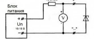
Straightening effect
According to this circuit, after the diode VD, the rectified signal Un goes to the load R (without filtering for now), where it is used for its intended purpose.
Note! If an alternating voltage of a certain amplitude U is applied to the input of a rectifier device, the current through it and the load R will flow only in one direction.
As a result of rectification, a series of positive half-waves will appear at the load, which are subsequently supplied to electrolytic capacitors for the purpose of filtering. Only after smoothing out the ripples through capacitors will it be possible to talk about the finally rectified voltage.
Pulse devices
A pulsed device is a device whose transition time from one state to another is short. They are used to work in pulse circuits. Such devices differ from their rectifier analogues by their small pn junction capacitances.
For devices of this class, in addition to the parameters indicated above, the following should be included:
- Maximum pulse forward (reverse) voltages, currents,
- Direct voltage installation period,
- Recovery period of the device's reverse resistance.
Schottky diodes are widely used in high-speed pulse circuits.