Alternating voltage is delivered from the energy supplying organization to consumers. This is due to the peculiarities of electricity transportation. But most household (and, partly, industrial) electrical receivers require constant voltage power. To obtain it, converters are required. In many cases, they are built according to the “step-down transformer – rectifier – smoothing filter” scheme (with the exception of switching power supplies). Diodes connected in a bridge circuit are used as a rectifier.
History of invention
In 1873, the English scientist Frederick Guthrie developed the operating principle of directly heated vacuum tube diodes.
A year later, in Germany, physicist Karl Ferdinand Braun suggested similar properties in solid-state materials and invented a point rectifier. In early 1904, John Fleming created the first complete tube diode. He used copper oxide as the material for its manufacture. Diodes have begun to be widely used in radio frequency detectors. The study of semiconductors led to the invention of the crystal detector in 1906 by Greenleaf Witter Pickard.
In the mid-30s of the 20th century, the main research of physicists was aimed at studying the phenomena occurring at the metal-semiconductor contact boundary. Their result was the production of a silicon ingot with two types of conductivity. While studying it, in 1939, the American scientist Russell Ohl discovered a phenomenon later called the pn transition. He found that depending on the impurities existing at the interface of two semiconductors, the reducibility changes. In the early 50s, Bell Telephone Labs engineers developed planar diodes, and five years later, germanium-based diodes with a transition of less than 3 cm appeared in the USSR.
The inventor of the rectifier bridge circuit is considered to be an electrical engineer from Poland, Karol Pollak. Later, the results of Leo Graetz’s research were published in the journal Elektronische Zeitung, so in the literature one can also find another name for a diode bridge - circuit or Graetz bridge.
What are diodes
A diode is a semiconductor element based on a silicon crystal. Previously, these parts were also made of germanium, but over time this material was forced out due to its shortcomings. The electrical diode functions as a valve, i.e. it allows current to flow in one direction and blocks it in the other. Such capabilities are built into this part at the level of the atomic structure of its semiconductor crystals.
One diode cannot obtain a full constant voltage from an alternating voltage. Therefore, in practice, more complex combinations of these elements are used. An assembly of 4 or 6 parts, combined according to a special circuit, forms a diode bridge. He is already quite capable of coping with full current rectification.
Interesting. Diodes have parasitic sensitivity to temperature and light.
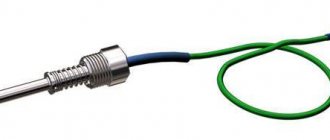
Transparent rectifiers in a glass case can be used as light sensors. Germanium diodes (approx. D9B) are suitable as a temperature-sensitive element. Actually, due to the strong dependence of the properties of these elements on temperature, they stopped producing them.
Definition
A diode bridge is a circuit solution designed to rectify alternating current. Another name is a full-wave rectifier. It is built from semiconductor rectifier diodes or their varieties - Schottky diodes.
The bridge connection circuit assumes the presence of several (for a single-phase circuit - four) semiconductor diodes to which the load is connected.
It can consist of discrete elements soldered on a board, but in the 21st century, connected diodes in a separate package are more common. Outwardly, it looks like any other electronic component - legs are removed from a case of a certain standard size for connection to the tracks of the printed circuit board.
It is worth noting that several valves combined in one housing, which are not connected via a bridge circuit, are called diode assemblies.
Depending on the scope of application and connection diagram, diode bridges are:
- single-phase;
- three-phase.
The designation on the diagram can be made in two versions; which UGO to use in the drawing depends on whether the bridge is assembled from individual elements or a ready-made one is used.
Checking elements
Often in homemade devices it is necessary to use parts that have already been used. All such components must be inspected before installation. Since the rectifier assembly consists of four diodes connected back-to-back in series, and the terminals of all diodes can be reached with a probe, the question of how to ring a diode bridge can be solved simply.
To do this, it is enough to measure the resistance of each diode with a regular ohmmeter, focusing on the rectifier circuit and the bridge pinout. In one polarity of the probes, the device should show high resistance, in the other - low. When the corresponding diode is broken, the resistance will be low in both positions of the probes; if it is burned out, it will be high.
Operating principle
Let's figure out how a diode bridge works. Let's start with the fact that diodes pass current in one direction. AC voltage rectification occurs due to one-way conduction of diodes. Due to their correct connection, the negative half-wave of the alternating voltage is supplied to the load in the form of a positive one. In simple words, it reverses the negative half-wave.
For simplicity and clarity, let's consider its operation using the example of a single-phase full-wave rectifier.
The operating principle of the circuit is based on the fact that diodes conduct current in one direction and is as follows:
- An alternating sinusoidal signal, for example 220V from a household electrical network, is supplied to the input of the diode bridge (in the connection diagram, the input of the diode bridge is designated as AC or ~).
- Each half-wave of sinusoidal voltage (figure below) is passed through a pair of valves located diagonally in the diagram.
The positive half-wave is transmitted by diodes VD1, VD3, and the negative half-wave by VD2 and VD4. You can see the signal at the input and output of the circuit below.
This signal is called rectified pulsating voltage. In order to smooth it out, a filter with a capacitor is added to the circuit.
Features of voltage types
A natural question arises about why alternating current is used in sockets, if the vast majority of electronic equipment is powered by direct current. The fact is that to power the nodes of this or that equipment, voltages of different magnitudes are required. A computer processor, for example, is powered by 3 V, and a mobile phone requires as much as 5 V to charge. A music center amplifier already needs about 25 V.
DC voltage is quite difficult to transform from one value to another, but alternating voltage is easy. For example, transformers are used for this. Some important power components, such as motors, still require AC power. Therefore, industrial generators that power household sockets produce it to a generally accepted value (for example, 220 V), and each device already receives from it what it needs on site.
Diode bridge circuit
One of the most important parts of electronic devices powered by a 220 volt AC network is the so-called diode bridge. A diode bridge is one of the circuit solutions on the basis of which the AC rectification function is performed.
As you know, most devices require direct current rather than alternating current to operate. Therefore, there is a need for rectification of alternating current.
For example, the power supply, which has already been discussed on the pages of the site, contains a single-phase full-bridge rectifier - a diode bridge. In the circuit diagram, the diode bridge is depicted as follows.
Diode bridge circuit
This is a so-called single-phase bridge rectifier, one of several types of rectifiers that are actively used in electronics. It is used to produce full-wave rectification of alternating current.
In hardware it looks like this.
Diode bridge from individual diodes
S1J37
This circuit was invented by the German physicist Leo Graetz , therefore this circuit solution is sometimes called the “ Graetz circuit ” or “ Graetz bridge ”. In electronics, this circuit is currently used everywhere. With the advent of cheap semiconductor diodes, this circuit began to be used more and more often. Now you won’t surprise anyone with it, but in the era of radio tubes the “Graetz bridge” was ignored, since it required the use of as many as 4 tube diodes, which were quite expensive at that time.
Types of diode bridges
Depending on the number of phases that are connected to the diode bridge, single-phase and three-phase models are distinguished. We examined the first option in detail using the example of the Graetz scheme above.
Three-phase rectifiers, in turn, are divided into six- and twelve-pulse models, although their diode bridge circuit is identical. Let us consider in more detail the operation of a diode device for a three-phase circuit.
Three-phase diode bridge circuit
The diode bridge shown in the figure above is called the Larionov circuit. Structurally, for each phase, two diodes are installed in the opposite direction relative to each other. It is important to note here that the sinusoid in all three phases has a shift of 120° relative to each other, therefore, at the outputs of the device, when the resulting diagram is superimposed, the following picture will appear:
Voltage rectified by a three-phase bridge
As you can see, in comparison with a single-phase rectifier based on a diode bridge, the picture turns out to be smoother, and voltage surges have a significantly smaller amplitude.
How does a diode bridge work?
A few words about how a diode bridge works. If an alternating current “~” ) , the polarity of which changes at a certain frequency (for example, with a frequency of 50 hertz, as in an electrical network), then at the output (terminals “+” and “-” ) we will receive a current strictly one polarity . True, this current will have ripples. Their frequency will be twice as high as the frequency of the alternating current supplied to the input.
Thus, if alternating current (frequency 50 hertz) is applied to the input of the diode bridge, then at the output we will obtain direct current with pulsations at a frequency of 100 hertz. These ripples are undesirable and can significantly interfere with the operation of the electronic circuit.
To “remove” pulsations, you need to apply a filter. The simplest filter is an electrolytic capacitor of sufficiently large capacity. If you look at the circuit diagrams of power supplies, both transformer and pulse, then after the rectifier there is always an electrolytic capacitor that smoothes out current ripples.
Designation of the diode bridge in the diagram.
On circuit diagrams, a diode bridge can be depicted in different ways. Take a look at the pictures below - they are all the same diagram, but they are depicted differently. I think that now, looking at an unfamiliar diagram, you will easily find it.
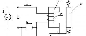
Bridge device type
A three-phase bridge rectification circuit uses six diodes (or thyristors if control is required). The output voltage is characterized by three values: minimum U, average U and peak voltage. A full-wave three-phase rectifier is similar to a Heitz bridge. Diagram of a full-wave three-phase device. A conventional three-phase rectifier does not use a neutral. For 230 V / 400 V network between two rectifier inputs. Indeed, there is always a composite voltage U (= 400 V) between the 2 inputs. An uncontrolled device means that the average output U cannot be adjusted for that input U. Uncontrolled rectification uses diodes.
Three-phase diode rectifier
A controlled rectifier allows you to regulate the average output voltage by influencing the response delay of the thyristor (used instead of diodes). This command requires complex electronic circuitry.
The diode behaves like a thyristor loaded without delay. Output U three-phase output voltage. There are 7 curves in total: 6 sinusoids and a red curve connecting the upper part of the sinusoids (“sinusoidal caps”). 6 sinusoids represent 3 voltages that make up U between phases and 3 identical voltages, but with opposite sign:
U31 = -U13U23 = -U32U21 = -U12.
The red curve represents U at the output of the rectifier, that is, at the terminals of the resistive load. This U does not refer to neutral. She swims. This U fluctuates between 1.5 Vmax and 1.732 Vmax (root of 3). Umax is the peak value of one voltage and is 230 × 1.414 = 325 V.
Properties of three-phase voltage
A curve acting only on a resistive load, uncontrolled rectification (with diodes), does not return to zero, unlike a monofrequency device (Graetz bridge). Thus, the ripple is much lower and the dimensions of the inductor and/or smoothing capacitor are less restrictive than for a Heitz bridge. At least two phases are required to obtain a non-zero output U. Minimum, maximum and average voltage value. Numerically, for a 230 V / 400 V network, the rectified voltage fluctuates between a minimum voltage: 1.5 V min = 1.5 x (1.414×230) = 488 V, and a maximum: 1.732 Vmax = 1.732 x (1.414×230) = 563 IN.
Average value of three-phase rectified voltage: avg = 1.654Vmax = 1.654 x (1.414×230) = 538 V. Output voltage of three-phase output rectifier (zoom). 3-phase full wave rectifier MDS 130A 400V. 5 terminals: 3 phases, + and -. This rectifier contains 6 diodes. Thus, the following points can be summarized:
- 6 diodes, 2 diodes per phase - weak ripple compared to a single-wave rectifier (Heetz bridge);
- average value of rectified voltage: 538 V for a network of 230 V / 400 V;
- the neutral is not used by the three-phase rectifier.
Diode bridge operation
It consists of four diodes and this configuration is connected across the load. During the positive half cycle of the input signals, diodes D1 and D2 are forward biased and D3 and D4 are reverse biased. When a voltage greater than the threshold level of diodes D1 and D2 begins to conduct, current begins to flow through it, as shown in the figure below on the red line. During the negative half cycle of the AC input signal, diodes D3 and D4 are forward biased and D1 and D2 are reverse biased. Load current starts flowing through diodes D3 and D4 when these diodes start conducting as shown in the figure.
In both cases, the direction of the load current is the same, as shown in the figure one way, which means DC. Thus, by using a bridge rectifier, the input current AC is converted to DC. The output to the load using this bridge rectifier is pulsating in nature, but to obtain pure DC, an additional filter such as a capacitor is required. The same operation is applicable for various bridge rectifiers, but in case of controlled rectifiers, the thyristor is triggered to control the current to the load.
Mode 1 (from α to π). In the positive half-cycle of the applied AC signal SC1, T1 and T2 are forward biased and can be turned on at an angle α. The load voltage is equal to the positive instantaneous AC supply voltage.
Mode 2 (π toπ + α). At wt = π the input power is zero, and after π it becomes negative. But inductance counteracts any changes to maintain the DC load and in the same direction.
Operation diagram of a three-phase rectifier
Reverse polarity protection
This charger is not afraid of a short circuit at the output, but if the polarity is reversed, it may fail. To protect against polarity reversal, a powerful Schottky diode can be installed in the gap in the positive wire going to the battery. Such diodes have a low voltage drop when connected directly. With such protection, if the polarity is reversed when connecting the battery, no current will flow. True, this diode will need to be installed on a radiator, since a large current will flow through it during charging.
Suitable diode assemblies are used in computer power supplies. This assembly contains two Schottky diodes with a common cathode; they will need to be paralleled. For our charger, diodes with a current of at least 15 A are suitable.
It must be taken into account that in such assemblies the cathode is connected to the housing, so these diodes must be installed on the radiator through an insulating gasket.
It is necessary to adjust the upper voltage limit again, taking into account the voltage drop across the protection diodes. To do this, use the voltage potentiometer on the DC-DC converter board to set 14.5 volts measured with a multimeter directly at the output terminals of the charger.
How to check a diode bridge
1st method.
As you now know, a single-phase diode bridge consists of 4 diodes. In order to find out their location, we must download the datasheet for this diode and see how the diodes are located in this diode bridge. For example, for my GBU6K bridge the diodes are located like this.
That is, all I need to do is just test each diode using a multimeter. I wrote how to do this in this article.
Second way.
He's 100%. But for this you will need an oscilloscope, LATR or step-down transformer, as well as a resistor, preferably 5-10 KOhm. After we have found its pin location, we solder a 5-10 KOhm resistor to “+” and “-”. We take an oscillogram from the same terminals.
That is, everything should look like this.
Let's look at the oscillogram
This means the diode bridge is working.
Video
Alatoys Lotto “Three Cats” Educational wooden toys Board game for children, 42 wooden chips, 7 cards, bag
409 ₽ More details
Alatoys Lotto “Letters and Numbers” Educational wooden toys Board game for children, 42 wooden chips, 7 cards, bag
409 ₽ More details
Wireless headphones with microphone
How to make a diode bridge with your own hands
If necessary, and if you have the necessary diodes and a soldering iron, it is not difficult to assemble a diode bridge with your own hands.
Selecting a build type
For each task there is its own optimal version of the rectifier diode assembly. All of them can be divided into 3 types:
- Rectifier with one diode. It is used in the simplest and cheapest circuits where there is no c.l. requirements for the quality of the output voltage, as, for example, in night lights.
- Dual diode. These parts look similar to transistors, because they are produced in the same packages. They also have 3 pins. Essentially, these are two diodes placed in one housing. One of the conclusions is average. It can be the common cathode or the anode of the internal diodes.
- Full diode bridge. 4 parts in one case. Suitable for devices with high currents. It is mainly used on the inputs and outputs of various power supplies and chargers.
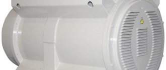
Additional Information. Rectifiers are also used in cars. They are needed to convert the alternating voltage coming from the generator to direct voltage. This, in turn, is necessary to charge the battery. A conventional gas generator produces alternating current.
What do you need for work?
To work, you need to prepare a workplace with a socket for a soldering iron, a soldering iron with a stand, solder, rosin, tweezers, and small wire cutters. Of course, you need diodes with the required characteristics. If desired, the bridge can be assembled on a printed circuit board with ready-made tracks.
Manufacturing instructions
| Illustration | Description of action |
| PHOTO: youtube.com | Preparation of the workplace |
| PHOTO: youtube.com | Soldering circuits |
| PHOTO: youtube.com | Instrument testing of the assembled circuit |
| PHOTO: youtube.com | Checking the circuit under load with a filter capacitor |
Functionality check
The first check is always visual. It is checked whether the parts are installed correctly, whether the circuit is assembled correctly, and the quality of soldering. Then a test circuit with a source and a measuring device is assembled. And if this stage was successful, then you can connect the load and conduct a final check of the results of your work.
Sources
- https://rusenergetics.ru/%D0%B1%D0%B5%D0%B7-%D1%80%D1%83%D0%B1%D1%80%D0%B8%D0%BA%D0%B8/ sxema-podklyucheniya-i-naznachenie-diodnogo-mosta
- https://amperof.ru/teoriya/diodnyj-most-sxema.html
- https://elektrik-sam.ru/baza-znanij/4139-chto-takoe-diodnyj-most-prostoe-objasnenie.html
- https://go-radio.ru/diodniy%20most.html
- https://www.asutpp.ru/diodnyy-most.html
- https://ElectroInfo.net/teorija/trehfaznyj-vyprjamitel.html
- https://www.RusElectronic.com/diodnyj-most/
- https://homius.ru/diodnyj-most-shema.html
- https://ElectroInfo.net/radiodetali/4-diodnyj-most.html
Device settings
Everyone knows that all car electronics are powered by 12V. In this case, the charging device must produce a current of 10% of the rated capacity. Without this, the memory will also work, but much slower.
To achieve these parameters, you will need:
- Transformer with 2 windings. The rule “the more turns, the better” applies here. If there are more windings, then it’s not scary. They just won't be used. Basically any pulse transformer will do.
- AC power comes from the outlet. A homemade car battery charger should provide a constant charger. In this case, you will need a rectifier.
- Tester. A multimeter is needed to determine the output voltage. It should be exactly 12 volts.
- It is impossible to make a battery charger without automatic control. Otherwise, the battery may explode. Therefore, a voltage control relay is necessary.
- Current adjustment will be required. A variable resistor will handle this. It is advisable to use a multi-turn current regulator so that the adjustment is smooth.
This is enough to assemble a simple charger.