An electric current transformer is an energy conversion device. The no-load current of the transformer characterizes losses in the absence of a connected load. The value of this parameter depends on several factors:
- Constructive design.
- Core material.
- Winding quality.
When manufacturing converters, they strive to reduce no-load losses as much as possible in order to increase efficiency, reduce heating, and also reduce the parasitic field of magnetic scattering.
General design and operating principle of the transformer
Structurally, the transformer consists of the following main parts:
- Closed core made of ferromagnetic material.
- Windings
The windings can be wound on a rigid frame or have a frameless design. Specially treated steel is used as the cores of industrial frequency voltage transformers. In some cases, there are devices without a core, but they are used only in the field of high-frequency circuitry and will not be considered within the framework of this topic.
The operating principle of the design in question is as follows:
- When the primary winding is connected to an alternating voltage source, it generates an alternating electromagnetic field.
- Under the influence of this field, a magnetic field is formed in the core.
- The magnetic field of the core, due to electromagnetic induction, creates an induced emf in all windings.
The induced emf is created, among other things, in the primary winding. Its direction is opposite to the connected voltage, so they cancel each other and the current through the winding when there is no load is zero. Accordingly, the power consumption when there is no load is zero.
Idle concept
The above reasoning is valid for an ideal transformer. Real designs have the following losses (disadvantages):
- core magnetization;
- core scattering magnetic field;
- electromagnetic dissipation of the winding;
- interturn capacitance of winding wires.
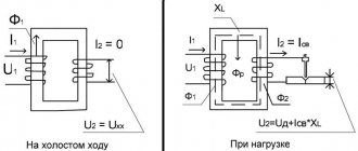
As a result, in real transformer designs, the induced induced emf differs from the rated voltage of the primary winding and is not able to fully compensate for it. Some no-load current occurs in the winding. When a load is connected, this value is summed with the rated current and characterizes the total losses in the electrical circuit.
Losses reduce the overall efficiency of the transformer, resulting in increased power consumption.
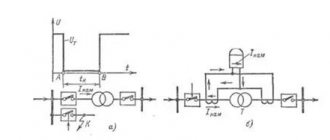
The principle of operation of a transformer in idle mode
When a sinusoidal voltage is applied to the winding of the device, a weak current appears in it, usually not exceeding 0.05-0.1 of the rated value (this is the no-load current). It is created by a winding magnetomotive force; it is because of its action that a leading magnetic flux (denoted F) and a scattering flux F1, closed around the winding body, arise in a closed magnetic conductor element. The value of the magnetomotive force is equal to the product of the no-load current and the number of winding turns.
Transformation ratio
The leading flow creates two electromotive forces in the device: self-induction in the first winding and mutual induction in the second. F1 produces a leakage emf at the first coil. It has a very small value, because the flow that creates it is closed, for the most part, through air masses, the leading flow F is through the magnetic circuit. Since the main flow has a much larger scale, the electromotive force it generates for the primary coil is also much larger.
Important! Since the supplied voltage has the form of a sinusoid, the main flow and the winding electromotive forces it creates have the same characteristics. But due to magnetic saturation, the flux present in the device is disproportionate to the electric current that creates magnetization, so the latter will not be sinusoidal. It is practiced to replace its real curve with a corresponding sinusoid with the same value. Current distortion is associated with the third harmonic component (a value determined by eddy flows and magnetic saturation).
Measures to reduce no-load current
The main source of no-load current is the design of the magnetic circuit. In a ferromagnetic material placed in an alternating electric field, eddy currents of electromagnetic induction are induced - Foucault currents, which heat the core material.
To reduce eddy losses, the core material is made of thin plates separated from each other by an insulating layer, which is provided by an oxide film on the surface. The material itself is produced using a special technology in order to improve magnetic properties (increasing the value of magnetic saturation, magnetic permeability, reducing hysteresis losses).
The downside of using a large number of plates is that the magnetic flux breaks at the joints, resulting in a stray field. Therefore, for stacked cores, careful adjustment of the individual plates to each other is important. In strip split magnetic cores, individual parts are adjusted to each other by grinding, so when assembling the structure, parts of the core cannot be swapped.
O-shaped magnetic cores are free from these disadvantages. Their magnetic scattering field tends to zero.
The dissipation field of the winding and the interturn capacitance are reduced by changing the design of the windings and the spatial placement of their parts relative to each other.
Reducing losses is also achieved by filling the free window of the core as completely as possible. At the same time, the weight and dimensions of the device tend to be optimal.
Transformer parameters based on no-load experiments
The device passport indicates a number of quantities that can help in calculating such operational indicators as the maximum short-circuit current value obtained in practice, energy losses, and the amplitude of receiver voltage variability with a changing current. These quantities are divided into two groups. The first belongs to operation in idle mode: this includes the current strength as a percentage of the nominal and the power losses of the magnetic circuit. The second is winding losses during a short circuit and the voltage (also indicated relative to the nominal) in this state.
How is the idle test performed?
The no-load experience involves applying voltage to the primary winding when there is no load. Using connected measuring instruments, the electrical parameters of the structure are measured.
To conduct the no-load experiment, the primary winding is connected to the network in series with a device for measuring current - an ammeter. A voltmeter is connected parallel to the terminals.
It should be borne in mind that the measurement limit of the voltmeter must correspond to the applied voltage, and when choosing an ammeter, it is necessary to take into account the approximate values of the measured value, which depend on the power of the transformer.
Transformation ratio
The transformation coefficient is most simply determined. To do this, the input and output voltages are compared. The calculation is made using the following formula:
This relationship is valid for all windings of the transformer.
Single-phase transformers
In single-phase transformers, the ammeter readings characterize the current consumed when there is no load. These readings are final and there is no need for further calculations.
Three-phase
To test a three-phase transformer, a more complex connection diagram is required. The following devices are required:
- ammeters for measuring current in each phase;
- voltmeters for measuring phase-to-phase voltages of the primary winding;
- voltmeters for measuring phase-to-phase voltages of the secondary winding.
When conducting an idle test, the following calculations are made:
- the average current value is calculated based on the ammeter readings;
- average voltage value of the primary and secondary windings.
The transformation ratio is calculated from the obtained voltage values similarly to a single-phase system.
Idle experience
With the help of testing it is possible to establish:
- transformation ratio;
- how do current, power, and no-load power coefficient cosφ depend on the applied voltage;
- power losses in a steel magnetic circuit.
From the very name of the experiment it follows that it is carried out when the terminals of the secondary winding remain open, and the input power is supplied from the high voltage side. A reverse circuit is also used with power supply from the LV side and opening of the primary winding terminals.
The transformer no-load test is performed by connecting the selected winding to an alternating current power source through various instruments: ammeter, voltmeter, wattmeter. In order to establish the transformation ratio, a voltmeter is also connected on the other side. The applied voltage can be varied during the test. As a rule, its regulation occurs in the range of 0.6-1.1 from the nominal value.
Scheme for test x.x.
In an unloaded device, the primary current is very low - 3-5% of In. Losses in the wires of the transformer winding are insignificant.
Important! Transformer in idle mode. operates at Un, the generated magnetic flux in the steel magnetic core corresponds to the highest values. Almost all energy consumption is used to heat the core.
Measurements to calculate the transformation ratio
- After supplying the supply voltage, readings from two voltmeters are recorded synchronously. The transformation ratio is then calculated according to the formula:
K = U1/U2.
For three-phase devices, readings of phase or line voltages are taken;
- When connecting the windings of three-phase devices ∆/Y and Y/∆, the phase coefficient is measured by applying voltage to one phase and short-circuiting the others in turn. On the delta side, one phase is short-circuited and the remaining phases are energized. The calculated phase coefficient must be multiplied by 2 if the voltage is applied to Y, and divided by 2 if it is ∆.
Important! The phase coefficient value is calculated when significant deviations of the linear indicator are observed.
Definition of losses
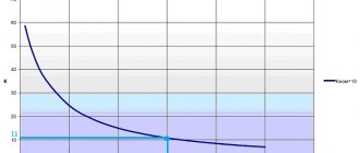
Graphic characteristics of no-load (no-load) are constructed based on several values of current, voltage and power read from devices in the process of voltage regulation. Quantitative current values for devices with low power indicators do not exceed 10% of the nominal values, and for high-power devices - 2%.
Formula for calculating the no-load power factor:
cosφ = P/I x U.
Important! In x.x mode. cosφ is 0.2-0.3.
The power indicator measured by a wattmeter is the power loss in the steel core.
You can also define:
- magnetizing component of the current x.x.:
Im = I x sinφ
- active part of the current x.x.:
Ia = I x cosφ
- reactance:
X = U/Im
- resistance representing active losses in the magnetic circuit:
R = U/Ia.
Equivalent circuit in transformer mode
Direct electrical calculation of a transformer is complicated because it consists of two electrical circuits connected by a magnetic circuit.
To simplify calculations, it is more convenient to use a simplified equivalent circuit. In the equivalent circuit, instead of windings, complex resistances are used:
- for the primary winding, the complex resistance is connected in series in the circuit;
- for the secondary winding parallel to the load.
Each complex resistance consists of a series-connected active resistance and inductance.
Active resistance is the resistance of the winding wires.
What does the magnetic flux of mutual induction in XX mode depend on?
The magnetic flux of mutual induction in a transformer depends on the method of placing the windings on the core and their design.
An important role is played by the fill factor of the magnetic circuit window, which shows the ratio of the total space to the space occupied by the winding.
The closer this coefficient is to unity, the higher the mutual inductance of the windings will be and the lower the losses in the transformer.
, Ohm
3.
Contents and order of work
To study the electrical circuit according to the diagram in Fig. 1P measurement protocol uses: DC voltage sources from the POWER MODULE
: voltage source
E
1 = 9 V (
UZ 1
), current source
J
2
=
50 mA (
UZ 2
);
measuring instruments from
DC MEASURING
MODULE Passive elements and the electrical circuit are selected from the RESISTOR
MODULE ; for the resistor
Rn
the RESISTANCE STORE is used .
· Assemble the electrical circuit according to the diagram shown in Fig. 1P. Check the assembled electrical circuit in the presence of a teacher.
Turn on the QF
POWER MODULE
block .
Turn on toggle switch SA 1
of sources
UZ 1
and
UZ 2
.
Set the value of resistor R
n =
R
1. If the arrows of ammeters
PA 1, PA 2
and
PA 3
the MEASURING MODULE
block deviate to the right, then the current value is considered positive and equal to the device reading. If the arrow of the device deviates to the left, the polarity of the device connection should be reversed, and the current value should be considered negative. The voltages on the elements are measured similarly with a PV voltmeter.
· Enter the values of measured currents and voltages into the table. 1P of the measurement protocol.
Determination of equivalent generator parameters
In short circuit mode ( R
n
=
0) measure the current
I
short-circuit and the currents of the branches.
· In idle mode (branch with R
n open) measure voltage
U
xx, no-load current. Enter the measurement data into the table. 1P.
Comparison of experimental and theoretical data
· Fill out the table. 2P.
Determination of experimental dependencies
Measure currents I
n,
I
1, voltage
U
n for those indicated in the table.
3P resistance values R
n. Enter the measurement data into the table. 3P protocol.
P from measurements
n.
· Turn off the QF
POWER MODULE
block .
· Construct experimental dependencies I
n(
Rn
),
Un
(
In
),
Pn
(
In
),
I
1(
I
3).
Measurement protocol for laboratory work No. 3
“Equivalent generator method. Linear relationships"
The diagram of the electrical circuit under study is shown in Fig. 1P. Indicate on the diagram under study the positive directions of currents in the branches and the polarity of connecting the devices. In subsequent experiments, the selected directions are taken as positive; the experimental value of the current in the branches is taken in accordance with the deflection of the instrument needle.
E
1 = ___ V,
J
2 = ___ mA, = ____ Ohm, = ____ Ohm, Ohm.
R
n = ____ Ohm
, mA
, mA
, mA
, mA
Transformer no-load detection
Transformers are complex equipment that is designed to change the current parameters in a circuit. They can increase or decrease the power and voltage of electricity in accordance with the requirements of consumers.
During operation, some power losses are detected in the equipment. Therefore, not all the electricity that enters the primary winding reaches the consumer. At the same time, the transformer (magnetic drive, windings and other parts) heats up. This indicator is not the same in different designs.
The no-load operation of the transformer makes it possible to determine current losses. This technique is used in combination with voltage determination in transformer short-circuit mode. This process is called aggregate experience. It is carried out according to a certain scheme.
- 1 General structure and types 1.1 Main types
- 1.2 Features of installations
- 2.1 Measurement approach
- 3.1 Single-phase devices
- 5.1 Using a wattmeter
Determination of transformer no-load current
The current generated in the primary winding of a transformer during no-load operation at rated sinusoidal voltage and rated frequency is called no-load current.
When calculating the no-load current of a transformer, its active and reactive components are determined separately.
The active component of the no-load current is caused by the presence of no-load losses.
Active current component, A:
, (7.19)
where Рх – no-load losses, W;
Uph – phase voltage of the primary winding, V.
Usually, it is not the absolute value of the no-load current and its components that is determined, but their relative value in relation to the rated current of the transformer i
oa,
i
op,
i
o, expressing them as a percentage of the rated current.
Then the active component, %:
, (7.20)
where S is the power of the transformer, kVA;
Рх – no-load losses, W.
The calculation of the reactive component of the no-load current is complicated by the presence of non-magnetic gaps in the magnetic circuit of the transformer. In this calculation, the magnetic system of the transformer is divided into four sections - rods, yokes, with the exception of the corners of the magnetic system, corners and gaps. For each of these sections, the required magnetizing power is calculated, which is then summed over the entire magnetic system. Just like losses, the reactive component of the no-load current depends on the basic magnetic properties of the steel of the magnetic system and a number of design and technological factors that have a significantly greater influence on this component than on losses [5].
And so for a flat three-phase laminated magnetic system with mutual arrangement of rods and yokes, assembled from plates of cold-rolled anisotropic steel , the total magnetizing power can be calculated by the formula, VA:
, (7.21)
where Gс, Gя/ and Gу are the masses of steel rods, individual parts of yokes and corners, respectively, kg;
qс and qя – specific magnetizing powers for steel rods and yokes, (determined according to Table 7.5), VA/kg;
qз – specific magnetizing power for gaps, determined according to Table 7.5, by induction for straight and oblique joints, similar to рз when calculating no-load losses, VA/m2;
Pz – gap area, determined in the same way as when calculating no-load losses, m2;
kt.r – coefficient taking into account the effect of cutting the coil strip on the plates: for annealed steel kt.r=1.18, for unannealed steel kt.r=1.49;
kt.z is a coefficient that takes into account the effect of cutting burrs: for annealed plates kt.z=1.0, for unannealed plates kt.r=1.01;
kt.y is a coefficient that takes into account the number of angles with oblique and straight joints of the magnetic system plates according to Table 7.6;
kt.pl - coefficient taking into account the width of the plates in the corners of the magnetic system according to Table 7.7;
kt.i – coefficient taking into account the cross-sectional shape of the yoke, kt.i=1.0 for a yoke with a multi-stage section and kt.i=1.07 for a yoke of rectangular cross-section (with the ratio of the number of legs of the rod and yoke equal to three, kt.i= 1.04; with a ratio of six kt.i=1.06);
kt.p is a coefficient that takes into account the pressing of the magnetic system according to Table 7.4;
kt.sh - coefficient taking into account the over-mixing of the upper yoke, equal to 1.01 with a transformer power of up to 250 kVA; 1.02 at powers of 400-630 kVA.
Table 7.5 - Total specific magnetizing power in steel q [V∙A/kg] and in the area of the laminated joint q3 for cold-rolled steel grades 3404 and 3405 with a thickness of 0.35 and 0.30 mm at various inductions and f = 50 Hz
| V, T | Steel grade and thickness | qз, V∙A/m2 | ||||
| 3404, 0.35 mm | 3404, 0.30 mm | 3405, 0.35 mm | 3405, 0.30 mm | |||
| 1 | 2 | 3 | 4 | 5 | 6 | 7 |
| 0,20 | 0,040 | 0,040 | 0,039 | 0,038 | ||
| 0,40 | 0,120 | 0,117 | 0,117 | 0,115 | ||
| 0,60 | 0,234 | 0,230 | 0,227 | 0,223 | ||
| 0,8 | 0,375 | 0,371 | 0,366 | 0,362 | ||
| 1,00 | 0,548 | 0,540 | 0,533 | 0,525 | ||
| 1,20 | 0,752 | 0,742 | 0,732 | 0,722 | ||
| 1,22 | 0,782 | 0,768 | 0,758 | 0,748 | ||
| 1,24 | 0,811 | 0,793 | 0,783 | 0,773 | ||
| 1,26 | 0,841 | 0,819 | 0,809 | 0,799 | ||
| 1,28 | 0,870 | 0,844 | 0,834 | 0,824 | ||
| 1,30 | 0,900 | 0,870 | 0,860 | 0,850 | ||
| 1,32 | 0,932 | 0,904 | 0,892 | 0,880 | ||
| 1,34 | 0,964 | 0,938 | 0,924 | 0,910 | ||
| 1,36 | 0,996 | 0,972 | 0,956 | 0,940 | ||
| Continued from Table 7.5 | ||||||
| 1 | 2 | 3 | 4 | 5 | 6 | 7 |
| 1,38 | 1,028 | 1,006 | 0,988 | 0,970 | ||
| 1,40 | 1,060 | 1,040 | 1,020 | 1,000 | ||
| 1,42 | 1,114 | 1,089 | 1,065 | 1,041 | ||
| 1,44 | 1,168 | 1,139 | 1,110 | 1,082 | ||
| 1,46 | 1,222 | 1,188 | 1,156 | 1,123 | ||
| 1,48 | 1,276 | 1,238 | 1,210 | 1,161 | ||
| 1,50 | 1,330 | 1,289 | 1,246 | 1,205 | ||
| 1,52 | 1,408 | 1,360 | 1,311 | 1,263 | ||
| 1,54 | 1,486 | 1,431 | 1,376 | 1,321 | ||
| 1,56 | 1,575 | 1,511 | 1,447 | 1,383 | ||
| 1,58 | 1,675 | 1,600 | 1,524 | 1,449 | ||
| 1,60 | 1,775 | 1,688 | 1,602 | 1,526 | ||
| 1,62 | 1,958 | 1,850 | 1,748 | 1,645 | ||
| 1,64 | 2,131 | 2,012 | 1,894 | 1,775 | ||
| 1,66 | 2,556 | 2,289 | 2,123 | 1,956 | ||
| 1,68 | 3,028 | 2,681 | 2,435 | 2,188 | ||
| 1,70 | 3,400 | 3,073 | 2,747 | 2,420 | ||
| 1,72 | 4,480 | 4,013 | 3,547 | 3,080 | ||
| 1,74 | 5,560 | 4,953 | 4,347 | 3,740 | ||
| 1,76 | 7,180 | 6,364 | 5,551 | 4,736 | ||
| 1,78 | 9,340 | 8,247 | 7,161 | 6,068 | ||
| 1,80 | 11,500 | 10,130 | 8,770 | 7,400 | ||
| 1,82 | 20,240 | 17,670 | 15,110 | 12,540 | ||
| 1,84 | 28,980 | 25,210 | 21,450 | 17,680 | ||
| 1,86 | 37,720 | 32,750 | 27,790 | 22,820 | ||
| 1,88 | 46,460 | 40,290 | 34,130 | 27,960 | ||
| 1,90 | 55,200 | 47,830 | 40,740 | 33,100 | ||
| 1,95 | 89,600 | 82,900 | 76,900 | 70,800 |
Note: when blending into one plate, multiply the q3 data by 0.82 for steel grade 3404 and by 0.78 for steel grade 3405.
Table 7.6 - Values of the coefficient kt.u., for a different number of angles with oblique and straight joints of plates of a flat laminated magnetic system for steel grades 3404 and 3405 with a thickness of 0.35 and 0.30 mm at f = 50 Hz
| Number of corners with joints | Induction V, T | |||||
| oblique | straight | 1,4 | 1,5 | 1,6 | 1,7 | 1,8 |
| — | 26,0 | 27,95 | 27,95 | 26,0 | 22,10 | |
| 5* | 1* | 32,25 | 34,83 | 35,20 | 33,25 | 27,85 |
| 38,5 | 41,7 | 42,45 | 40,5 | 33,66 | ||
| — | 58,5 | 64,7 | 65,6 | 64,7 | 52,0 |
Table 7.7 - Values of the coefficient kt.pl, taking into account the increase in magnetizing power in the corners of the magnetic system depending on the width of the plate of the second package a2 for cold-rolled steel
| V, T | Width of the plate of the second package a2, m | |||||||
| 0,05 | 0,10 | 0,20 | 0,30 | 0,40 | 0,50 | 0,60 | 0,70 | |
| 0,8-1,00 | 1,30 | 1,25 | 1,20 | 1,17 | 1,15 | 1,14 | 1,13 | 1,12 |
| 1.10 and 1.90 | 1,40 | 1,27 | 1,21 | 1,18 | 1,16 | 1,15 | 1,14 | 1,13 |
| 1.20 and 1.80 | 1,50 | 1,30 | 1,22 | 1,19 | 1,17 | 1,16 | 1,15 | 1,14 |
| 1.30 and 1.70 | 1,70 | 1,38 | 1,25 | 1,21 | 1,18 | 1,17 | 1,16 | 1,15 |
| 1.40 and 1.60 | 2,00 | 1,50 | 1,35 | 1,25 | 1,20 | 1,19 | 1,18 | 1,16 |
| 1,50 | 3,00 | 2,0 | 1,50 | 1,35 | 1,30 | 1,25 | 1,20 | 1,18 |
Absolute phase value of the reactive component of the no-load current, A:
(7.22)
The relative value of the no-load current as a percentage of the rated current of the transformer (similar to the active component i
oa) , %:
(7.23)
Total no-load current, A:
Ix = (7.24)
and as a percentage of rated current:
io =
(7.25)
The resulting value of the no-load current is i0
should be checked with the no-load current according to the instructions for calculating the transformer - I0, i.e. this deviation should not exceed 70%.
Previous9Next
WHAT AND HOW THEY WRITTEN ABOUT FASHION IN MAGAZINES AT THE BEGINNING OF THE XX CENTURY The first issue of the Apollo magazine for 1909 began, in fact, with a policy statement from the magazine’s editors...
WHAT HAPPENS IN ADULT LIFE? If you are still connected to your mother in the wrong way, you are avoiding separation and independent adult existence...
WHAT HAPPENS WHEN WE FIGHT Without understanding the differences that exist between men and women, it is very easy to lead to a quarrel...
What to do if there is no reciprocity? And now let's come down from heaven to earth. Have you landed? Let's continue the conversation...
Didn't find what you were looking for? Use Google search on the site:
General structure and types
To understand what the no-load experience of various transformers is, it is necessary to consider what such equipment is.
Main types
Transformers are stationary machines that operate using electric current. They change the input voltage. There are several types of such devices:
- Power.
- Measuring.
- Separating.
- Coordinators.
Most often, a power transformer is required to be connected to the energy circuit. They may have two or more windings. The device can be single-phase (domestic network) or multi-phase (industrial network).
Features of installations
Autotransformers stand out separately. They have only one combined winding. There is also a welding machine. They have a specific scope of application.
Single-phase and multi-phase equipment may have different power ratings. It can be defined in the range from 10 to 1000 kVA or more. Low-power single-phase and multi-phase devices can be in the range of up to 10 kVA. Medium varieties will have a power of 20 kVA, 250 kVA, 400 kVA, 630 kVA, etc. If this figure is more than 1000 kVA, this is a high power unit.
No-load three-phase transformer
The nature of the operation of a 3-phase device in XX mode depends on the magnetic system and the winding connection diagram:
- the primary coil is a “triangle”, the secondary is a “star” (D/Y): there is a free circuit of the TGS current I1 through the windings of the device. Therefore, the magnetic flux and EMF are sinusoidal and the unwanted processes described above do not occur;
- Y/D circuit: the magnetic flux TGS appears, but the current from the additional EMF induced by it flows freely through the secondary coils closed in a “triangle”. This current creates its own flux of the magnetic induction vector, which extinguishes the third GS of the main MF that causes it. As a result, the magnetic flux and emf have an almost sinusoidal shape;
- star connection of the primary and secondary coils (Y/Y).
In the last circuit, the TGS of current I1 is absent, since there is no path for it: the third harmonies of each of the phases at any time are directed towards the zero point or away from it. Because of this, the magnetic flux is distorted.
The rest is determined by the magnetic system:
- A 3-phase transformer in the form of a group of 1-phase ones : the magnetic flux TGS is closed in each phase along its own core and, due to the low magnetic resistance of the latter, reaches an amplitude of 15% - 20% of the operating magnetic flux. It creates an additional EMF, the amplitude of which can already reach 45% - 60% of the main EMF. Such an increase in voltage can lead to insulation breakdown with subsequent breakdown of electrical installations;
- transformers with an armored rod magnetic system : the same phenomena occur (the third harmonic magnetic flux is closed along the side yokes of the magnetic circuit);
- three-rod magnetic system: the TGS has no path along the magnetic circuit and is closed through a medium with low magnetic permeability - air, oil, tank walls. Therefore, it has a small value and does not induce significant additional EMF.
Scheme of no-load experiment of a three-phase two-winding transformer
The presence of a delta connection in the 3-phase transformer circuit largely neutralizes the negative influence of the TGS magnetic flux and improves the EMF curve.
In powerful installations for high voltages, where a star connection of the windings on both sides is required, an additional non-working winding (does not carry an electrical load) is installed, connected in a triangle.
Experiment methodology
The no-load losses of the transformer are determined when creating a certain mode. To do this, the current supply to all windings is stopped. They remain open. After this, the circuits are supplied with electricity. It is determined only on the first circuit. The equipment must operate under the voltage that is set by the manufacturer during its production.
Currents flow through the primary circuit of a power, welding or other installation, which are called XX. Their value is no more than 3-9% of the indicator specified by the manufacturer. In this case, there is no electricity on the secondary circuit winding. In the primary circuit, current produces magnetic flux. It crosses the turns of both windings. In this case, an EMF of self-induction occurs on the primary circuit and mutual induction on the secondary winding.
For example, the open-circuit voltage of a low- and medium-power welding transformer represents the mutual induction emf.
Measurement approach
Measuring no-load losses can be done in two aspects. They are called steel and copper losses. The second indicator indicates heat dissipation in the windings (they begin to heat up). During the experiment this figure is very small. Therefore they are neglected.
Transformation ratio
When determining the operation of an installation, a concept such as transformation ratio is used. Its formula is presented below:
It follows that the voltage on the secondary circuit will be determined by the ratio of the number of turns. To be able to regulate the output electricity, a special device is built into the design of the installation. It switches the number of turns on the primary circuit. This is an antsapf.
To conduct the experiment at idle, the regulator is placed in the middle position. In this case, the coefficient is measured.
Single-phase devices
To carry out the presented experiment, when using a step-down or step-up household unit, the presented coefficient is taken into account. In this case, two voltmeters are used. The first device is connected to the primary winding. Accordingly, the second voltmeter is connected to the secondary circuit.
The input impedance of the measuring instruments must correspond to the nominal characteristics of the installation. It can operate in buck or boost mode. Therefore, if it is necessary to carry out repair work, not only the supply of low but also high voltage is measured on it.
Three-phase devices
For three-phase units, during the experiment, indicators on all circuits are examined. In this case, you will need to use 6 voltmeters at once. You can use one device that will be connected in turn to all measurement points.
If the value set by the manufacturer on the primary winding exceeds 6 kV, a current of 380 V is supplied to it. When measuring in high-voltage mode, it is impossible to determine indicators with the required accuracy class. Therefore, measurements are carried out in low voltage mode. It is safe.
Applying the coefficient
During the measurement process, the trunnion is moved to all positions specified by the manufacturer. In this case, the transformation coefficient is measured. This allows you to determine the presence of a short circuit in the turns.
If the phase readings have a scatter during measurements of more than 2%, as well as their decrease in comparison with previous data, this indicates deviations in the operation of the unit. In the first case, a short circuit is detected in the system, and in the second, a violation of the insulation of the windings is detected. The unit may not operate correctly.
Such facts require confirmation. For example, this could be a resistance measurement. An increase in the spread of the coefficient indicators can be influenced by an increase in the resistance between the contacts of the axle. When switching frequently, this situation occurs.
Single-phase transformer no-load
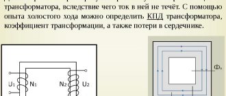
By no-load operation of a transformer we mean such a mode of its operation in which voltage is supplied to the terminals of the primary winding, and the secondary winding is open, that is, the secondary current is zero.
No-load is the limiting operating mode, which allows you to determine such important quantities as: transformation ratio, no-load current of the transformer, no-load losses of the transformer.
Figure 2.2.1 – Magnetic fluxes in a transformer
Let a harmonic voltage be applied to terminals A-X of the primary winding of the transformer,
| ; | (2.2.11) |
under the influence of which current i
0. This current creates a magnetizing force
i
0
w
1, where w1 is the number of turns of the primary winding connected in series.
N.s. the primary winding causes a magnetic flux to appear. This flow has several components: Ф
0 - the main flow, which makes up most of the total flow, is closed along the core and meshes with both windings;
Фσ
1 – leakage flux of the primary winding, closes outside the core, couples only with the primary (possibly partially with the secondary) winding.
Flow F
0 induces the main EMF in the primary winding,
e
1 and in the secondary -
e
2. Flux Фσ1 - creates a leakage EMF
e σ
1 in the primary winding.
Since current i
0, then across its active resistance
r
1 there is a voltage drop i0r1. According to Kirchhoff's second law, we can write:
| (2.2.12) |
or in vector form:
| (2.2.13) |
In transformers of conventional design, the leakage flux at no-load (Pst) is small, r
1 is also small and usually does not exceed 5% of . Therefore, as a first approximation, this difference can be neglected. Then equation (2.2.13) has the form:
| ; | (2.2.14) |
that is, at no-load, the voltage supplied to the transformer winding is practically balanced only by the EMF created in this winding by the main magnetic flux.
According to the law of electromagnetic induction:
| (2.2.15) |
The term “–π” in formula (2.2.15) indicates that and are in antiphase, which follows from (2.2.14). In order to find the connection between the EMF and the amplitude of the main flow, we integrate (2.2.15):
| (2.2.16) |
where:
| (2.2.17) |
Formula (2.2.17) can be represented as:
| (2.2.18) |
Where:
| (2.2.19) |
or:
| (2.2.20) |
| (2.2.21) |
Expression (2.2.21) is the main one in the theory of transformers for calculating the effective value of the EMF.
From this expression it follows that if frequency f
and the number of turns are given, then the EMF is directly proportional to the flux.
The secondary winding is penetrated by the same flux Фm
, therefore, the effective value of the EMF of the secondary winding, similar to equation (2.2.21), can be written as:
| ; | (2.2.22) |
Ratio E
1 to
E
2 is called the transformation coefficient of the transformer, it can be determined by dividing expression (2.2.21) by (2.2.22), then
| . | (2.2.23) |
All of the above is for the simplest single-phase transformer (that is, a transformer for which r
1≈0 and
Lσ1
≈0) can be illustrated with the corresponding vector diagram.
Figure 2.2.2 – Vector diagram of ideal idle speed
Voltage U
1 under the influence of which a current i0 flows, which, due to the assumption of r1 ≈0 and Pst ≈0, is purely inductive in nature and, therefore, the vector lags behind by π/2. The current i0 creates a n.s., under its action a flow arises, which also lags behind by π/2 (see equation (2.2.17)). The flow creates an emf in the windings. and , and in accordance with (2.2.14) is in antiphase with the applied voltage .
According to the law of magnetic circuit
| , | (2.2.24) |
Where:
Rµ
is the magnetic resistance of the core, which is a function of µst.
In an unsaturated mode (µst = const) Ф
0 and
i
0 are directly proportional, but in a saturated mode with a sinusoidal
Ф
0
i
0 is non-sinusoidal, and has, as can be seen from Figure 2.2.3, a peak-shaped character.
Figure 2.2.3 – Shape of the magnetizing current in a saturated transformer
Since the vector diagram is constructed for sinusoidal quantities, the 1st harmonic or equivalent sinusoid is usually isolated from the magnetizing current curve.
All of the above applied to the simplest transformer, i.e. dissipation and losses of active power were not taken into account. In a real transformer, active power losses are calculated using the formula:
| , | (2.2.25) |
where I0a
– effective value of the active component of the no-load current.
Thus, in a real transformer the current is x.x. has two components - a magnetizing component with an effective value I0µ, which creates the main flux and is in phase with it, and an active component I0a, which is in phase with the voltage vector U
1.
Figure 2.2.4 – No-load current of a real transformer
By adding these two components geometrically, we can calculate the total x.x.:
| (2.2.26) |
Usually in transformers I0a << I0µ (less than 10%, and most often less than 0.5%), therefore this component does not have a significant effect on the value of I0. (I0a has a slightly stronger effect on the phase and shape of the current x.x.)
Let us now return to equation (2.2.13) of a real single-phase transformer and construct a vector diagram in accordance with it.
Figure 2.2.5 – Vector diagram of the no-load circuit of a real transformer
Let's draw the vector in the positive direction of the x-axis. The vector lags behind the flux vector by π/2; is in phase with . Current vector x.x. is built according to its active and magnetizing components. Vector e.m.f. leakage of the primary winding equal to –j I
0
xσ
1, where
xσ
1 is the leakage inductive reactance of the primary winding lags behind . To construct the voltage vector in accordance with equation (2.2.13), it is necessary to geometrically add the vectors , and .
Power P
0, consumed by the transformer in x.x mode. is spent entirely on covering chemical losses, which have several components:
A) losses in the copper of the primary winding, equal to
| ; | (2.2.27) |
B) the main losses in the steel of the pco core;
B) additional losses of h.h.
Typically, losses in copper at cold temperatures are make up no more than 2% of the amount of losses of chemical products, so they are neglected.
Idle power is practically spent only on steel losses. The main losses in steel consist of losses due to hysteresis (magnetization reversal) and eddy currents, with 85% of these losses (at a frequency of 50 Hz) being hysteresis losses. Both hysteresis and eddy current losses depend on the square of the core induction, in addition Pin
depend on the square of the frequency, and
PG
- on the frequency to the first power.
Usually
| , | (2.2.28) |
for frequencies close to 50 Hz, Рс1-loss in 1 kg of steel at V
=1T.
Additional losses x.x. usually make up 15-20% of Pco
and there are the following types:
a) losses in steel from changes in the structure of sheets during machining;
b) losses at joints and at stud locations;
c) losses in structural parts - in studs, transformer tank, etc.
d) losses in insulation of high voltage transformers.
2.1.3 Transformation of three-phase current
A three-phase transformer can be made from three single-phase ones if their windings are connected in a certain way. Such a transformer is called a group transformer. A three-phase transformer can be three-rod.
A group transformer is more expensive than a rod transformer for the same power, has a lower efficiency and takes up more space. But in this case, it is enough to have one phase as a reserve. Since damage to two phases at the same time is unlikely. (Whereas in a rod one you need to have a backup transformer). At high powers, a group transformer is indispensable from the point of view of transportation and operating conditions.
In a group transformer, the magnetic system of each phase is independent, and the lengths of the magnetic circuits of the phases are equal. In a three-rod transformer, the lengths of the magnetic circuits are different, and for the outer phases the length of the magnetic circuit is greater than for the middle one, therefore, to create a symmetrical system of fluxes, an asymmetrical system of magnetizing fluxes is necessary, since I0 of the outer phases is greater than I0 of the middle one. In a group transformer there is no such asymmetry; in a three-rod transformer it is smoothed out even at a small load.
2.1.3.1 Schemes and connection groups of a three-phase transformer
In domestic transformers, winding connections are used: star, triangle, zigzag.
When connecting star Y, the ends of the windings form a common point, and the beginnings go to the network. When connecting the windings into a triangle Δ, the beginning of the first phase winding is connected to the end of the second, the beginning of the second to the end of the third, the beginning of the third to the end of the first, and the vertices of the resulting triangle are connected to the network. In a zigzag connection, each phase of the secondary winding is located on two different rods.
Generally speaking, the concepts of the beginning and end of the windings are conventional; they are necessary for the correct connection of the phase windings. In a three-phase transformer, the positive direction of the current from the beginning to the end of the winding must correspond to a certain direction of flow in the rods.
The beginnings of phase HV windings are usually designated by capital letters A, B, C, their ends are X, Y, Z, respectively; for LV windings these designations are a, b, c, and x, y, z, respectively. If the winding is connected by a star and has a zero point, then the designation is used.
When switching on a transformer for parallel operation, the method of connecting the windings, which is determined by the connection group, is of great importance. The group number corresponds to the angle between the linear voltage vectors of the HV and LV windings, measured clockwise from the linear voltage vector of the HV winding. The unit of angular movement is taken to be an angle of 300. There are 12 connection groups - from 0 to 11. (Previously, the zero group was called 12).
Methodology for determining groups of transformers.
Let's consider one phase of a three-phase transformer. If the low and high voltage windings are wound in one direction, that is, either on the left or on the right screw-
Figure 2.1.7- Groups of connections for a single-phase transformer
line, the upper terminals of the windings are taken as their beginnings, and the lower terminals as their ends, then the EMF (vectors) induced in the windings, firstly, are parallel, because are induced by the same flow, and secondly, they are directed in one direction. If the terminals of the LV winding are remarked, then EA
and
Ea
will be directed parallel, but counter. When constructing the VD necessary to determine the group, it should also be taken into account that if in the diagram the ends of the windings are connected at one point, then in the vector diagram the corresponding points of the phase voltage vectors, indicated by the same letters, are also connected together.
Typically, the vectors of linear EMF windings are likened to the hands of a clock dial, and the HV vector is taken to be the minute hand set at 12, and the LV vector is taken to be the hour hand, and the number to which the hour hand points determines the transformer group. Let a three-phase transformer have a star connection of the HV and LV windings. Wherein:
Figure 2.1.8 – Three-phase transformer with star connection diagram
1) the LV and HV windings have the same winding;
2) the beginnings and ends of the windings are located equally;
3) windings of the same name are located on common rods (for example, A and a, B and c).
Let us now construct the VD of the phase and linear EMF of the HV and LV windings.
Figure 2.1.9 – Three-phase transformer with a group of connections Y/Y-0
In this case, the EMF vectors of the same name are in phase, and if the compatibility on the dial is with the number 12, then the “hour hand” will show 12 or 0 “o’clock”.
If now in the Y/Y circuit the beginnings and ends of the LV windings are swapped, then in the LV VD the vector will change direction to the opposite, and the “clock” will show the 6th group. By circularly remarking the phases of the LV winding, you can obtain groups 4 and 8 by swapping the beginnings and ends: 2 and 6, i.e. all even groups. Even groups are also obtained by combining Δ / Δ, and odd ones - Δ/Y and Y/Δ.
Let us now consider the Y/Δ connection.
Figure 2.1.10 – Three-phase transformer with diagram and group of connections Y/D-11
It can be seen from the figure that the linear EMF vector LV is shifted by 300 relative to the HV vector and will be located opposite the number 11. By re-marking the terminals, groups 1,3,5,7 and 9 can be obtained. To ensure parallel operation of transformers in the Russian Federation, transformers are manufactured: Y/ Y0-0; Δ /Y0-11, Y0 / Δ -11, Y / -11; to the left of the fraction -VN; on the right is NN; “0” – output of the zero point outside. Y/Y0-0 - used at 10/0.4 and 6/0.4 kV, with uneven phase load: Y / - 11; 35/10 kV and 35/6 - Y / Δ-11, with ULN>110 kV - Y0 / Δ -11.
From the point of view of the influence of higher harmonics and behavior under asymmetrical loads, it is advisable to connect one of the windings in a triangle, since in this case zero-sequence currents and harmonics divisible by three disappear in the external circuit.
2.1.3.2 Magnetization of three-phase transformer cores
In the theory of a single-phase transformer, we found out that if a sinusoidal voltage is supplied to the primary winding, then the main flux is also sinusoidal, but the magnetizing current has higher harmonics. Similar phenomena occur in a three-phase transformer.
Δ/Y connection.
If the phase voltage is sinusoidal, then F
too, and , and will contain odd higher harmonics, multiples of 3. The main harmonics of the phases will be shifted relative to each other by 1200; the third -3·1200 =3600 or 0, the fifth - 5·1200=6000 or 240o, etc. Those. harmonics that are multiples of three in individual phases of the winding will be in phase. In line currents that are equal to the difference of the corresponding phase currents, these harmonics will be absent. Those. the currents of these harmonics will circulate within the closed triangle, forming a total closed circulating current.
Y/Δ connection.
In this case, there are no harmonics that are multiples of three in the primary magnetizing current, since they must be in phase and their sum must be equal to zero, but this cannot be. Therefore, the non-sinusoidal flux of the third harmonic Ф3Y will induce in the secondary winding connected by a triangle, three equal in magnitude and in phase E3Δ, and they. in turn, the current is I3Δ. The Ф3Δ created by this current will almost completely compensate for Ф3Y.
So: When connecting one of the transformer windings into a triangle, the flow F
and phase voltage
U
remain sinusoidal. Only in the phases of a winding connected by a triangle will current harmonics divisible by three circulate. All this applies to group transformers and transformers with a common core.
Y/Y connection: In this case, the currents on both sides cannot contain third harmonics, so the flux is non-sinusoidal, and therefore the phase emfs are non-sinusoidal. and U
.
But linear E
and
U
are sinusoidal, because in the difference in emf. two E3 phases disappear. In group (a), armored and armored-rod transformers, F3 is closed by the magnetic system, but in rod-type (b) transformers they cannot be closed by the core, since they are in phase.
Therefore, F3 from one yoke to another are closed through oil and air, fasteners and the walls of the tank, causing eddy current losses in them.
a) b)
Figure 2.1.11 – Third harmonics of flow in three-phase cores
transformers
Therefore, in powerful high-voltage transformers the Y / Y connection is not used. If there is such a need, then an additional tertiary winding with a delta connection can be wound in the transformer, the cross-section of which is designed only for currents I3.
| | | next lecture ==> | |
| Typical structural elements. | | | Engineering analysis in mechanical engineering |
Date added: 2016-06-18; views: 5862; ORDER A WORK WRITING
Find out more:
Loss measurement
Losses in the magnetic drive are measured exclusively when using a powerful installation. In this case, you can take for calculations a reduced voltage, which is connected to the primary circuit through a wattmeter. This is a direct measurement method.
When taking into account the readings of a voltmeter or ammeter, you will need to multiply their powers by each other. This is an indirect method. However, the result has a certain error. The distortion occurs due to the inability to take into account the power factor in such a calculation. This is the cone angle that is formed in a vector circuit between voltage and current. In idle mode, an angle of 90º appears between them.