If you look at the printed circuit board of even the simplest electronic device, you will definitely see a capacitor, and most often you will see many of these elements. The presence of these products in various electronic circuits is explained by the properties of these radioelements and the wide range of functions that they perform.
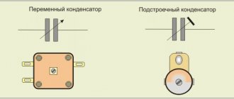
Currently, the industry supplies the market with capacitor products of various types (Fig. 1). Product parameters vary widely, which makes it easy to select a radio component for a specific purpose.
Rice. 1. Common types of capacitors
Let's take a closer look at the designs and basic parameters of these ubiquitous radioelements.
What is a capacitor?
In the classical sense, a capacitor is a radio-electronic device designed to accumulate the energy of an electric field, having the ability to accumulate an electric charge, with the subsequent transfer of the accumulated energy to other elements of the electrical circuit. The devices are very often used in various electrical circuits.
Capacitors are capable of accumulating charge very quickly and just as quickly releasing all the accumulated energy. Their work is characterized by the cyclical nature of this process. The amount of accumulated electricity and the periods of charge-discharge cycles are determined by the characteristics of the products, which in turn depend on the type of model. The parameters of these quantities can be determined by the product labeling.
Electrical capacity
In previous lessons, we became acquainted with elementary electrical concepts and principles, in particular, we talked about electrification - the phenomenon of charge redistribution. Let's start our conversation about a deeper study of this phenomenon with experience.
Initially, let us be given two insulated jars of different sizes connected to an electroscope (Fig. 1):
Rice. 1
Now an equally charged body was brought to each of the cans. Naturally, an electrification process will occur with each jar, and the arrows of both electroscopes will diverge. However, it turned out that the electroscope of the larger jar showed less deviation (Fig. 2):
Rice. 2
This experiment proves that different bodies are electrified by the same charge in different ways (specifically, a large jar was charged with the same charge to a lower potential). And there is a certain value that shows the body’s ability to accumulate electrical charge. Actually, that’s what we’ll be talking about.
Definition. Electrical capacitance (capacitance) is a value equal to the ratio of the charge transferred to a conductor to the potential of this conductor.
Here: – capacity; – transferred charge; – the potential to which the conductor is charged.
Design and operating principle
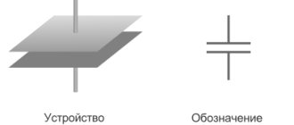
The simplest capacitor is two metal plates separated by a dielectric. The air space between the plates can act as a dielectric. A model of such a device is shown in Fig. 2.
Rice. 2. Model of the simplest capacitor device
If a constant voltage is applied to the structure, a short-term closed electrical circuit is formed. Charges will be concentrated on each metal plate, the polarity of which will correspond to the polarity of the applied current. As charges accumulate, the current will weaken, and at a certain point the circuit will break. In our case, this will happen at lightning speed.
When a load is connected, the accumulated energy will flow through the load element in the opposite direction. There will be a short-term surge of electric current in the formed circuit. The amount of accumulated charges (capacity, C) directly depends on the size of the plates.
The unit of measurement of capacitance is usually called the farad (F). 1 F is a very large value, so in practice multiple values are often used: microfarads (1 μF = 10-6 F), nanofarads (1 nF = 10-9 F = 10-3 μF), picofarads (1 pF = 10-12 F = 10-6 µF). The milifarada value is very rarely used (1 mF = 10-3 F).
The designs of modern capacitors differ from the model we are considering. In order to increase the capacity, instead of plates, plates made of aluminum, niobium or tantalum foil separated by dielectrics are used. These puff strips are tightly rolled into a cylinder and placed in a cylindrical housing. The principle of operation is no different from that described above.
There are also flat capacitors, structurally consisting of many thin plates, pressed between layers of dielectric in the shape of a parallelepiped. Such models can be imagined as a stack of plates, forming many pairs of plates connected in parallel.
The following are used as dielectrics:
- paper;
- polypropylene;
- Teflon;
- glass;
- polystyrene;
- organic synthetic films;
- enamel;
- barium titanite;
- ceramics and various oxide materials.
A separate group consists of products in which one lining is made of metal, and the second is an electrolyte. This is a class of electrolytic capacitors (example in Figure 3 below). They differ from other types of products due to their large specific capacity. Oxide semiconductor models have similar properties. Their second anode is a semiconductor layer deposited on an insulating oxide layer.
Rice. 3. Design of radial electrolytic capacitor
Electrolytic models, as well as most oxide semiconductor capacitors, have unipolar conductivity. Their operation is permissible only if there is a positive potential at the anode and at rated voltages. Therefore, the polarity of connecting the mentioned radio-electronic elements should be strictly observed.
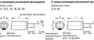
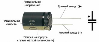
The polarity must be indicated on the body of such a device (a light strip with “–” signs, see Fig. 4) or the “+” sign on the side of the positive electrode on the cases of old domestic capacitors.
Figure 4. Pin polarity designation
The life of the electrolytic capacitor is limited. These devices are very sensitive to high voltages. Therefore, when choosing a radio element, try to ensure that its operating voltage is significantly higher than the rated voltage.
General concept
A capacitor consists of two conductive plates and a dielectric between them. And that's it, nothing more. It looks like a simple radio component, but it works differently at high and low frequencies.
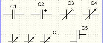
Indicated on the diagram by two parallel lines.
Principle of operation
This radio component demonstrates well the phenomenon of electrostatic induction. Let's look at it with an example.
If you connect a constant current source to the capacitor, then at the initial moment of time the current will begin to accumulate on the plates of the capacitor. This occurs due to electrostatic induction. Resistance is practically zero.
The electric field, due to electrostatic induction, attracts opposite charges to two opposite plates. This property of matter is called capacity. All materials have a capacity. And even for dielectrics, but for conductors it is much greater. Therefore, the capacitor plates are made of conductor.
The larger the capacitance, the more charges can accumulate on the capacitor plates, i.e. electric current.
The main property of a capacitor is capacitance. It depends on the area of the plates, the distance between them and the dielectric material that fills the space between the plates.
As charges accumulate, the field begins to weaken and the resistance increases. Why is this happening? There is less and less space on the plates, like charges on them act on each other, and the voltage on the capacitor becomes equal to the current source. This resistance is called reactive or capacitive. It depends on the frequency of the current, the capacitance of radio components and wires.
When there is no room left on the plates for the electric current, the current in the circuit will stop. Electrostatic induction disappears. Now there remains an electric field that holds the charges on its plates and does not let them go. And the electric current has nowhere to go. The voltage across the capacitor will become equal to the emf (voltage) of the current source.
What happens if you increase the EMF (voltage) of the current source? The electric field will begin to put more and more pressure on the dielectric, since there is no more space on the plates. But if the voltage on the capacitor exceeds the permissible limits, the dielectric will break through. And the capacitor will become a conductor, the charges will be released, and the current will flow through the circuit. How then to use a capacitor for high voltages? You can increase the size of the dielectric and the distance between the plates, but this reduces the capacitance of the part.
Between the plates there is a dielectric that prevents the passage of direct current. This is precisely the barrier to direct current. Because constant current also creates constant voltage. And a constant voltage can create electrostatic induction only when the circuit is closed, that is, when the capacitor is charging.
This way the capacitor can store energy until a consumer connects to it.
Capacitor and DC circuit
Let's add a light bulb to the diagram. It will only light up while charging.
Another important feature is that when the current charging process occurs, the voltage lags behind the current. The voltage seems to catch up with the current, since the resistance increases smoothly as it charges. Electrical charges take time to move to the capacitor plates. This is the charging time. It depends on capacitance, frequency and voltage.
As it charges, the light begins to glow dimmer.
The light goes out when fully charged.
Direct electric current does not pass through the capacitor until it is charged.
AC circuit
What if you change the polarity on the current source? Then the capacitor will begin to discharge and charge again as the polarity of the source changes.
Electrostatic induction occurs constantly if the electric current is alternating. Every time the current begins to change its direction, the process of charging and discharging begins.
Properties
From the description it is clear that for direct current the capacitor is an insurmountable barrier, except in cases of dielectric breakdown. In such electrical circuits, a radio element is used to accumulate and store electricity on its electrodes. A change in voltage occurs only in cases of changes in the current parameters in the circuit. These changes can be read and acted upon by other circuit elements.
In sinusoidal current circuits, a capacitor behaves like an inductor. It passes alternating current, but cuts off the direct component, which means it can serve as an excellent filter. Such radio-electronic elements are used in feedback circuits, included in oscillatory circuit circuits, etc.
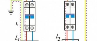
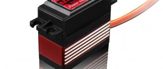
Another property is that variable capacitance can be used to shift phases. There are special starting capacitors (Fig. 5) used to start three-phase electric motors in single-phase electrical networks.
Rice. 5. Start capacitor with wires
What is the difference between polar and non-polar?
Non-polar ones allow the inclusion of capacitors in a circuit without taking into account the direction of the current. The elements are used in filters for variable power supplies and high-frequency amplifiers.
Polar products are connected in accordance with the markings. If turned on in the reverse direction, the device will be damaged or will not work normally.
Polar and non-polar capacitors of large and small capacity differ in dielectric design. In electrolytic capacitors, if the oxide is applied to 1 electrode or 1 side of the paper, film, then the element will be polar.
Models of non-polar electrolytic capacitors, in the designs of which the metal oxide is deposited symmetrically on both surfaces of the dielectric, are included in circuits with alternating current.
Polar ones have a positive or negative electrode marking on the body.
Main parameters and characteristics
Capacity.
An important parameter of a capacitor is its nominal capacity. For a flat capacitor the formula is valid:
С = (ε*ε 0 *S) / d,
where ε is the dielectric constant of the dielectric, S is the dimensions of the plates (plate area), d is the distance between the plates (plates).
The actual capacity of individual elements is usually small, but you can get a structure with a capacity of several farads if you connect a huge number of plates in parallel. In this case, the real capacity is equal to the sum of all the capacitances of the plates.
The maximum capacitance of some capacitors can reach several farads.
Specific capacity.
A value characterizing the ratio of capacity to volume or mass of a radio component. This parameter is important in microelectronics, where the dimensions of the parts are very important.
Rated voltage.
One of the important electrical characteristics is the rated voltage - the value of the maximum voltages at which the capacitor can operate without losing the values of its other parameters. When a critical value equal to the breakdown voltage is exceeded, the dielectric is destroyed. Therefore, the rated voltage is chosen to be obviously greater than any possible maximum amplitudes of the sinusoidal current in the capacitor circuit.
There are characteristics, such as loss tangent, temperature coefficient of capacitance, leakage resistance, dielectric absorption, etc., that are of interest only to specialists, and their parameters can be found in special reference books.
Behavior of a capacitor in an alternating current circuit
Strictly speaking, neither direct nor alternating current passes through the capacitor, since between the plates there is an insulator in which free electric charges cannot move.
Including a capacitor in a DC circuit is equivalent to breaking this circuit. As for alternating current, it will flow through the circuit in which the capacitor is connected, due to the periodic charge and discharge of this capacitor. Indeed, when a capacitor is charged, electrical charges, for example electrons, accumulate on one plate and leave on the other plate. In this case, they, of course, move along the connecting wires connected to the capacitor plates. The same movement of charges, only in the opposite direction, occurs when a capacitor is discharged.
If you connect a capacitor to an alternating current circuit, it will periodically charge in one polarity, then in the opposite. This means that electrons will accumulate on one plate or the other, and each time during charge and discharge, free electrons will move along the circuit in which the capacitor is connected, without, however, getting into the insulator connected between the plates. And since charges move in the capacitor circuit under the influence of alternating voltage, we believe that the capacitor passes alternating current, although in this case the charges do not pass through the insulator.
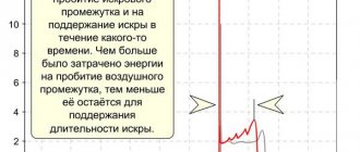
A capacitor affects the amount of alternating current in a circuit, and therefore (by analogy with Ohm's law) it is often considered as resistance. This so-called capacitive reactance is designated by the letter xc and, like ordinary resistance, is measured in ohms. The value of xc depends on the frequency of the alternating current and on the capacitance C of the capacitor: with a decrease in the capacitance of the capacitor, as well as with a decrease in the frequency of the alternating current, the capacitance of the capacitor increases (Fig. 80, 81, sheet 87). It is convenient to write this dependence as a simple formula:
The meaning of this formula is very simple: the smaller the capacitance C, the fewer charges will move to the plates with each charge and discharge of the capacitor; The lower the frequency of the alternating current, the less often the capacitor will charge and discharge. It follows that as f and C decrease, the current in the circuit decreases, or, in other words, the resistance of the capacitor increases.
This conclusion is of great practical importance. So, for example, if we need to include a capacitor with a very small capacitance in a circuit, then the capacitance of this capacitor will need to be selected taking into account the frequency of the alternating current in the circuit. For high frequencies it will be possible to take a small capacitor, but for low frequencies the capacitor will have to be large. This is well illustrated by a simple example. At a frequency of 100 kHz, a capacitor with a capacity of 100 pf has a capacitance of xc = 16 kohms. When the frequency decreases by 1000 times, that is, at a frequency of 100 Hz, the resistance of the capacitor will increase by 1000 times and become equal to 16,000 kΩ (16 MΩ). In order to ensure that the capacitance does not change when the frequency decreases, it is necessary to increase the capacitance of the capacitor. A resistance of 16 kohms at a frequency of 100 Hz will have a capacitor with a capacity of 100,000 pf (0.1 µf).
From the above formula it also follows that a decrease in the capacitance of the coupling capacitor CCB (sheet 85) will lead to an increase in the resistance of this capacitor, and therefore to a decrease in the current in the antenna circuit. Therefore, the SSV capacity cannot be taken too small.
This can be explained in another way. The coupling capacitor and the oscillatory circuit Lk Sk can be considered as a voltage divider to which the electric current is applied. d.s., acting between terminals A (“antenna”) and Z (“ground”). We will not talk for now about what the resistance of the oscillatory circuit is - even without this it is clear: the greater the capacitive resistance of the coupling capacitor, the smaller the part of e. d.s. will act on the lower part of the divider - on the circuit and the detector-telephone circuit connected to it.
Source
Classification
The main parameters of capacitor products are determined by the type of dielectric. The stability of the capacitance, the dielectric loss tangent, the piezoelectric effect and others depend on the material. Based on this, it is advisable to classify models according to the type of dielectric.
Based on this feature, the following types of products are distinguished:
- vacuum;
- with air dielectric;
- radioelements in which the dielectric is liquid;
- with a solid inorganic dielectric (glass, mica, ceramics). Characterized by low leakage current;
- models with paper dielectric and combined, paper-film;
- DC oil capacitors;
- electrolytic;
- category of oxide capacitors, which include oxide semiconductor and tantalum capacitors;
- solid-state, in which an organic polymer or polymerized semiconductor is used instead of a liquid electrolyte.
In solid-state models, the service life is longer than that of liquid electrolytic models and is about 50,000 hours. They have less internal resistance, that is, the ESR is almost independent of temperature, they do not explode.
Products are also classified according to another important parameter - change in capacity. Based on this feature they distinguish:
- permanent capacitors, that is, those that have a constant capacitance;
- variables in which the change in capacitance can be controlled mechanically or using applied voltage (varicaps and variconds), as well as by changing temperature (thermal capacitors);
- a class of tuning capacitors that are used to adjust or equalize working capacitances when setting up circuits, as well as for the purpose of periodically adjusting various circuits.
All existing capacitors can be divided into general and special. General purpose products include the most common low-voltage capacitors (see Fig. 6). There are no special requirements for them.
Rice. 6. General purpose capacitors
All other capacitive radioelements belong to the special purpose class:
- pulse;
- launchers;
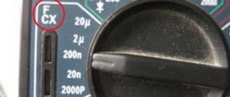
- high voltage (see Fig. 7);
- interference suppression
- dosimetric, etc.;
Rice.
7. High-voltage capacitors The devices shown in the photo can operate in high-voltage circuits of relatively low frequency.
Types of capacitors
Paper and metal-paper capacitors
In a paper capacitor, the dielectric separating the foil plates is special capacitor paper. In electronics, paper capacitors can be used in both low-frequency and high-frequency circuits.
Sealed metal-paper capacitors, which instead of foil (as in paper capacitors) use vacuum deposition of metal onto a paper dielectric, have good quality electrical insulation and increased specific capacitance.
A paper capacitor does not have great mechanical strength, so its filling is placed in a metal case, which serves as the mechanical basis of its design.
Electrolytic capacitors
In electrolytic capacitors, unlike paper capacitors, the dielectric is a thin layer of metal oxide formed electrochemically on a positive cover of the same metal.
The second cover is a liquid or dry electrolyte. The material that creates the metal electrode in an electrolytic capacitor can be, in particular, aluminum and tantalum. Traditionally, in technical jargon, “electrolyte” refers to aluminum capacitors with a liquid electrolyte.
But, in fact, electrolytic capacitors also include tantalum capacitors with a solid electrolyte (they are less common with a liquid electrolyte). Almost all electrolytic capacitors are polarized, and therefore they can only operate in DC voltage circuits while maintaining polarity.
In case of polarity reversal, an irreversible chemical reaction may occur inside the capacitor, leading to the destruction of the capacitor, even to its explosion due to the gas released inside it.
Electrolytic capacitors also include the so-called supercapacitors (ionistors) with an electrical capacity that sometimes reaches several thousand Farads.
Aluminum Electrolytic Capacitors
Aluminum is used as the positive electrode. The dielectric is a thin layer of aluminum trioxide (Al2O3),
- work correctly only at low frequencies;
- have a large capacity.
Characterized by a high capacitance-to-size ratio: Electrolytic capacitors are typically large in size, but another type of capacitor with the same capacitance and breakdown voltage would be much larger in size.
They are characterized by high leakage currents and have moderately low resistance and inductance.
Tantalum electrolytic capacitors
This is a type of electrolytic capacitor in which the metal electrode is made of tantalum and the dielectric layer is formed of tantalum pentoxide (Ta2O5).
- high resistance to external influences;
- compact size: for small ones (from several hundred microfarads), the size is comparable to or smaller than that of aluminum capacitors with the same maximum breakdown voltage;
- lower leakage current compared to aluminum capacitors.
Polymer capacitors
Unlike conventional electrolytic capacitors, modern solid-state capacitors have a polymer dielectric instead of an oxide film used as a plate separator. This type of capacitor is not subject to swelling and charge leakage.
The physical properties of the polymer contribute to the fact that such capacitors are characterized by high pulse current, low equivalent resistance and a stable temperature coefficient even at low temperatures.
Polymer capacitors can replace electrolytic or tantalum capacitors in many circuits, such as filters for switching power supplies, or in DC-DC converters.
Marking
A letter system was used to label domestic products. Today digital marking is common. The following symbols were used in the alphabetic system:
- K – capacitor;
- B, K, S, E, etc. – type of dielectric, for example: K – ceramic, E – electrolytic;
- In third place was a symbol indicating performance features.
In this marking system, the first letter was sometimes omitted.
In the new marking system, the letter K may appear first, followed by an alphanumeric code. Numbers are used to indicate the denomination, type of dielectric and development number. An example of such marking is shown in Figure 8. Please note that the switching polarity is indicated on the body of the electrolytic capacitor.
Rice. 8. Marking of capacitors
- Capacitance from 0 to 999 pF is indicated in picofarads, for example: 250p:
- from 1000 to 999999 pF – in nanofarads: n180;
- from 1 to 999 μF – in microfarads: 2μ5;
- from 1000 to 999999 µF – in millifarads: m150;
- Capacitance greater than 999999 μF is indicated in farads.
Electrical voltage
One of the most important parameters of the device we are considering is the breakdown voltage - the difference in potential values of the two conductors of the capacitor, leading to electrical breakdown of the dielectric layer. The maximum voltage at which breakdown of the device does not occur is determined by the shape of the conductors, the properties of the dielectric and its thickness. Operating conditions under which the voltage on the plates of an electrical device is close to the breakdown voltage are unacceptable. The normal operating voltage on the capacitor is several times less than the breakdown voltage (two to three times). Therefore, when choosing, you should pay attention to the rated voltage and capacitance. In most cases, the value of these quantities is indicated on the device itself or in the passport. Connecting a capacitor to the network at a voltage exceeding the rated one threatens its breakdown, and a deviation of the capacitance value from the nominal value can lead to the release of higher harmonics into the network and overheating of the device.
Connection of capacitors
There are two connection methods: parallel and serial. With a parallel connection, the total capacitance is equal to the sum of the capacitances of the individual elements: C total. = С 1 + С 2 + … + С n .
For a series connection, the capacitance calculation is calculated using the formula: Ctot. = ( C1* C2 *…* Cm ) / ( C1 + C2+…+Cn )
To quickly calculate the total capacitance of connected capacitors, it is better to use our calculators:
- https://www.asutpp.ru/kalkulyator-rascheta-posledovatelnogo-soedineniya-kondensatorov.html
- https://www.asutpp.ru/kalkulyator-rascheta-parallelnogo-soedineniya-kondensatorov.html
Application
Capacitors are used in almost all areas of electrical engineering. Let's list just a few of them:
- construction of feedback circuits, filters, oscillatory circuits;
- use as a memory element;
- for reactive power compensation;
- to implement logic in some types of protection;
- as a sensor for measuring liquid level;
- for starting electric motors in single-phase AC networks.
Using this radio-electronic element, it is possible to receive high-power pulses, which is used, for example, in photo flashes and in the ignition systems of carburetor engines.