Global trends - the demand for reducing CO2 emissions, increasing the intensity of energy conservation - lead to the need for balanced energy consumption, for which electronic process control circuits can be of great help. The most common cases are optimizing battery performance, controlling motor speed and transients in servers, and managing solar panels. It is important for operators of such systems, in particular, to know how much current flows in the circuit. Current sensors can provide invaluable assistance in this regard.
Why are current sensors needed?
Sensors are blocks whose task is to measure a certain parameter, and then, after comparing it with a reference value for a given technical system, send a corresponding signal to the actuator element of the circuit. Since most systems use electric motors, the most common types are current and voltage sensors (an overview of the latter is shown in the following figure).
The widespread introduction of such devices is due to the development of touch control methods, when the original signal - electrical or optical - is converted into the necessary control parameters.
Compared to other control technologies (e.g. contactor control), sensors provide the following advantages:
- Compactness.
- Safety in use.
- High accuracy.
- Environmentally friendly.
Small size and weight often allow the production of multifunctional sensors, such as those that can monitor multiple circuit parameters. These are modern current and voltage sensors.
These detectors include:
- Contact entry groups;
- Output contact groups;
- Shunt resistor;
- Signal amplifier;
- Carrier board;
- Power unit.
The idea that devices can be connected to an existing network does not stand the test of time, because often in extreme situations (fire, explosion, earthquake) it is the built-in power supply systems that are the first to fail.
Detectors are divided into active and passive. The former not only transmit the final signal to the control element, but also control its action.
Spectra of measured currents.
The voltage of three-phase AC power networks is usually subject to fairly stringent requirements - voltage waveform distortion (difference from the sinusoidal waveform), as a rule, should not be more than two percent. Similar requirements are usually imposed on the linearity of the phase electrical resistance of AC machines, therefore, in the current spectrum of a typical machine there are usually no strong harmonic components of the consumed current, but the frequency range in which there are informative current components is quite wide. Thus, Fig. 1 shows the shape and spectrum of the current in one of the phases of an asynchronous electric motor without strong defects. For clarity, the current spectrum along the ordinate axis is shown on a logarithmic scale.
Fig. 1. Shape of the current consumed by an asynchronous electric motor and its spectrum
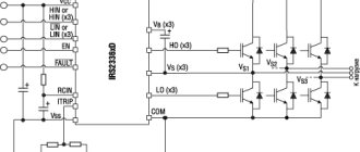
In recent years, the cheapest and most reliable asynchronous electric motor has been increasingly used as a drive motor, and a static frequency converter of the supply voltage is used to control its rotation speed and simplify starting. A three-phase voltage with a frequency of 50 Hz is supplied to the input of such a converter, and a three-phase voltage of a different frequency is generated at the output, which is optimal for the energy consumption of the unit or other controlled parameters. Naturally, the shape of the output voltage of such a converter, if it is not strictly standardized, as well as the current consumed by the electric motor, differs significantly from the sinusoidal one, and the current spectrum contains a large number of different components, as shown in Fig. 2.
Fig.2 Shape and spectrum of the current of an asynchronous electric motor when using a static frequency converter of the supply voltage.
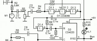
A similar situation arises with the supply voltage of DC motors. Typically, a DC motor is powered by a three-phase AC rectifier. If the speed control of the unit is organized in such a way that the rectified supply voltage does not change, distortions of the supply voltage and consumed current will be minimal, within 2% of the rectified voltage (armature current) and will appear mainly at a frequency of 300 Hz. But in most practical cases, the engine speed is controlled by a static rectified voltage regulator. The shape of the motor armature current when using the most common thyristor voltage regulator is shown in Fig. 3. The spectrum of the armature current is also shown there.
Rice. 3. Shape and spectrum of the armature current when powering a DC machine from a thyristor voltage regulator.
The above confirms the need to measure the spectrum of the current consumed by the electric motor, at least up to 10 kHz, when solving diagnostic problems of both the electric drive and the mechanism driven into rotation.
Classification and connection diagrams
Current sensors are designed to evaluate the parameters of direct and/or alternating current. The comparison is performed using two methods. In the first case, Ohm's law is used. By setting the shunt resistor according to the system load, a voltage is created across it that is proportional to the system load. The shunt voltage can be measured by differential amplifiers, such as current shunt, operational, or difference amplifiers. Such devices are used for loads that do not exceed 100 A.
AC current measurement is performed in accordance with Ampere's and Faraday's laws. When a loop is placed around a current-carrying conductor, a voltage is induced there. This measurement method is used for loads from 100 A to 1000 A.
The diagram of the described measurements is presented in the figure:
On the left - measurement of small currents; on the right - measurement of high currents
The measurement is usually made at a low input common mode voltage. Using a sensing resistor, the current sensor is connected between the load and ground. This is necessary because common mode voltage always takes into account the presence of op amps. The load provides power to the device, and the output resistance is grounded. The disadvantages of this method are the presence of interference associated with the system load potential to ground, as well as the inability to detect short circuits.
To monitor the operation of powerful systems, the detector is connected to an amplifier between the power source and the load. As a result, the values of the parameters supplied by the power supply are directly monitored. This allows possible short circuits to be identified. The peculiarity of the connection is that the common-mode voltage range at the amplifier input must correspond to the load supply voltage. Before measuring the output signal of the device being monitored, the load is grounded.
Sensor classification
At its core, each sensor is an integral part of regulatory, signaling, measuring and control devices. With its help, one or another controlled quantity is converted into a certain type of signal, which allows one to measure, process, register, transmit and store the received information. In some cases, the sensor may affect controlled processes. The current sensor used in many devices and microcircuits fully possesses all these qualities. It converts the effects of electric current into signals convenient for further use.
Sensors used in various devices are classified according to certain characteristics. If it is possible to measure input quantities, they can be: electrical, pneumatic, sensors of speed, mechanical movements, pressure, acceleration, force, temperatures and other parameters. Among them, the measurement of electrical and magnetic quantities takes approximately 4%.
Each sensor converts an input value into some output parameter. Depending on this, control devices can be non-electrical or electrical.
Among the latter, the most common are:
- DC sensors
- AC amplitude sensors
- Resistance sensors and other similar devices.
The main advantage of electrical sensors is the ability to transmit information over certain distances at high speed. The use of a digital code ensures high accuracy, speed and increased sensitivity of measuring instruments.
How does a current sensor work?
The operation of this element includes the following stages:
- Load measurement in a controlled circuit.
- Comparison of the obtained value with the reference value, which is programmed during the setup process.
- Recording the result obtained (can be done digitally or analogue).
- Transferring data to the control panel.
To perform these functions (in particular, to implement high measurement accuracy), the following requirements are imposed on the detector elements:
- The permissible voltage drop across the shunt resistor should be no more than 120...130 mV;
- The temperature error cannot be higher than 0.05%/°C and cannot change during operation;
- In the functional range of values, the resistance characteristics of the resistors should be linear;
- The method of soldering current-sensing resistors to the board cannot increase the total resistance of the connection circuit.
Wiring diagrams of devices that are designed to control DC and AC circuits are presented in the figures, respectively.
Typical options for integrated current meters
Based on the commercially available INA250 and INA260 ICs, TI has developed and offers a range of off-the-shelf reference solutions to demonstrate the current measurement process. The fully assembled TIDA-00614 and TIDA-01608 boards were specifically designed to test and evaluate the performance of integrated shunt current meters under specific conditions. But emphasizing the demonstration nature of the products, the company notes that these particular boards are not sold in finished form. To get acquainted with the capabilities of the microcircuits, other development boards are provided - INA260EVM and INA250EVM.
TIDA-00614 – bidirectional current meter with 30 A integral shunt
This board (Figure 4) allows you to accurately measure current in the range of up to 30 A on a bus with a common-mode voltage of up to 36 V at temperatures of -40...85°C. The load current is divided approximately in half between the circuits of the two shunt resistors. The voltage corresponding to the current of the first channel from the amplifier output (OUT) is supplied to the REF input of the second channel. The device sums the output voltages of the two INA250A2 ICs and generates a common output voltage relative to the GND pin. The diagram of the TIDA-00614 measuring board is shown in Figure 5.
Rice. 4. TIDA-00614 board
Features of TIDA-00614
- Compact design with good temperature characteristics
- Stable current measurement up to 30 A using two amplifiers with integrated current sensing shunts connected in parallel
- Configurable for full and partial, positive and negative bidirectional current measurement ranges
- The device package includes documentation, design data and board layout files.
Rice. 5. Electrical diagram of the current measuring board TIDA-00614
TIDA-01608 – isolated current sensor with integrated shunt resistor and I²C interface
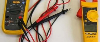
Figure 6 shows the assembled board of the TIDA-01608 meter, and Figure 7 shows the circuit diagram of the device. The board can accurately measure hundreds of volts of bus current and is an example of devices being developed for solar power equipment and server power supplies with their need for a wide range of high-level input voltages. The TIDA-01608 board contains: an INA260 chip with an integrated resistive shunt for current measurement, two P82B96 bidirectional buffers that simplify I²C connections, an ISOW7842 digital isolator that provides galvanic isolation of measurement and control circuits. The common-mode voltage measured by the INA260 is limited to 36 V, so using the ISOW7842 allows the designer to solve the problem of measuring current in high-voltage circuits.
Rice. 6. TIDA-01608 board
Features of TIDA-01608
- HV bus current measurement (±1 kV)
- Isolated high voltage load circuits
- I²C bus compatible
- Reinforced isolation of digital I²C interface with microcontroller
- System error 1%
Rice. 7. Electrical circuit of the current measuring board TIDA-01608
Application practice
Most often, these products are used as meters in current relay circuits, which control the operating modes of various electric drive equipment and protect it from extreme situations.
Current relays can protect any mechanical device from stalling or other overload conditions that result in a noticeable increase in load on the motor. Functionally, they detect current levels and produce an output signal when a specified value is reached. Such relays are used for:
- Signals from high-current conditions, for example, a coffee grinder filled to the brim with beans;
- Some low current conditions, such as running a pump when the water level is low.
To meet the demands of a diverse set of applications, modular sensor designs are now being used, including USB connectors, DIN rail mounting, and ring-type devices. This provides the following functions:
- Reliable operation in any operating modes;
- Possibility of using transformers;
- Adjustment of current parameters, which can be fixed or adjustable;
- Analog or digital output, including short circuit option;
- Various versions of power supplies.
As an example, consider a current sensor circuit to control the operation of a water pump that supplies water to a house.
Cavitation is a destructive condition caused by the presence of bubbles that form when a centrifugal pump or vertical turbine pump operates with low fluid levels. The resulting bubbles then burst, which leads to pitting corrosion and destruction of the pump control unit. A current relay prevents such a situation.
When the pump is operating normally and the fluid is completely blocking the pump inlet, the pump motor draws its rated operating current. If the water level decreases, the current consumption decreases. If the start button is pressed, the starter M and timer TD are activated simultaneously. The CD relay is set to maximum current, so its contact will not be closed when the engine is initially started. When the current drops below the set minimum, the relay is turned on, and, after the waiting time TD has expired, it is connected to its normally closed contact. Accordingly, the CR contacts open and de-energize the pump motor.
The use of such a detector eliminates the automatic restart of the pump, since the operator must ensure that the liquid level in front of the inlet is sufficient.
DIY current sensor
If for some reason it is impossible to purchase a standard sensor (the best known designs are from the Arduino brand), you can make the device yourself.
Arduino current sensor. The arrow indicates the USB connector.
Required components:
- Op amp LM741, or any other that could act as a voltage comparator.
- Resistor 1 kOhm.
- Resistor 470 Ohm.
- Light-emitting diode.
A general view of the assembled device, made by yourself, is shown in the following figure. This circuit uses the Hall effect, when the control potential difference can change when the location of the conductor in the electromagnetic field changes.