Date of publication: March 26, 2013. Category: Articles.
When an electrical circuit is closed, at the terminals of which there is a potential difference, an electric current occurs. Free electrons, under the influence of electric field forces, move along the conductor. In their movement, electrons collide with conductor atoms and give them a supply of their kinetic energy. The speed of electron movement continuously changes: when electrons collide with atoms, molecules and other electrons, it decreases, then under the influence of an electric field it increases and decreases again during a new collision. As a result, a uniform flow of electrons is established in the conductor at a speed of several fractions of a centimeter per second. Consequently, electrons passing through a conductor always encounter resistance to their movement from its side. When electric current passes through a conductor, the latter heats up.
Electrical resistance
The electrical resistance of a conductor, which is denoted by the Latin letter r, is the property of a body or medium to convert electrical energy into thermal energy when an electric current passes through it.
In the diagrams, electrical resistance is indicated as shown in Figure 1, a.
| Figure 1. Symbol for electrical resistance |
Variable electrical resistance that serves to change the current in a circuit is called rheostat . In the diagrams, rheostats are designated as shown in Figure 1, b. In general, a rheostat is made of a wire of one resistance or another, wound on an insulating base. The slider or rheostat lever is placed in a certain position, as a result of which the required resistance is introduced into the circuit.
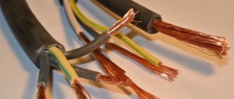
A long conductor with a small cross-section creates a large resistance to current. Short conductors with a large cross-section offer little resistance to current.
If you take two conductors from different materials, but the same length and cross-section, then the conductors will conduct current differently. This shows that the resistance of a conductor depends on the material of the conductor itself.
The temperature of the conductor also affects its resistance. As temperature increases, the resistance of metals increases, and the resistance of liquids and coal decreases. Only some special metal alloys (manganin, constantan, nickel and others) hardly change their resistance with increasing temperature.
So, we see that the electrical resistance of a conductor depends on: 1) the length of the conductor, 2) the cross-section of the conductor, 3) the material of the conductor, 4) the temperature of the conductor.
The unit of resistance is one ohm. Om is often represented by the Greek capital letter Ω (omega). Therefore, instead of writing “The resistance of the conductor is 15 ohms,” you can simply write: r = 15 Ω. 1,000 Ohms is called 1 kiloohm (1kOhm, or 1kΩ), 1,000,000 Ohms is called 1 megaohm (1mOhm, or 1MΩ).
When comparing the resistance of conductors from different materials, it is necessary to take a certain length and cross-section for each sample. Then we will be able to judge which material conducts electric current better or worse.
Video 1. Conductor resistance
Ohm's law [edit]
Main article: Ohm's law
The current-voltage characteristics of four devices: two resistors, a diode, and a battery.
The horizontal axis represents the voltage drop, and the vertical axis represents the current. Ohm's law holds when the graph is a straight line through the origin. Therefore, the two resistors are ohmic
, but the diode and battery are not.
For many materials the current I
V
applied to it :
I ∝ V {\displaystyle I\propto V}
over a wide range of voltages and currents. Therefore, the resistance and conductivity of objects or electronic components made from these materials are constant. This relationship is called Ohm's law, and materials that obey it are called ohmic
materials. Examples of ohmic components are wires and resistors. The graph of a current-voltage ohmic device consists of a straight line passing through the origin with a positive slope.
Other components and materials used in electronics do not obey Ohm's law; current is not proportional to voltage, so resistance depends on voltage and current through them. They are called nonlinear
or
non-ohmic
. Examples include diodes and fluorescent lamps. The current-voltage curve of an ohmless device is a curved line.
Electrical resistivity
The resistance in ohms of a conductor 1 m long, with a cross-section of 1 mm² is called resistivity and is denoted by the Greek letter ρ (rho).
Table 1 shows the resistivities of some conductors.
Table 1
Resistivities of various conductors
| Conductor material | Specific resistance ρ in |
| Silver Copper Aluminum Tungsten Iron Lead Nickelin (alloy of copper, nickel and zinc) Manganin (alloy of copper, nickel and manganese) Constantan (alloy of copper, nickel and aluminum) Mercury Nichrome (alloy of nickel, chromium, iron and manganese) | 0,016 0,0175 0,03 0,05 0,13 0,2 0,42 0,43 0,5 0,94 1,1 |
The table shows that an iron wire with a length of 1 m and a cross-section of 1 mm² has a resistance of 0.13 Ohm. To get 1 Ohm of resistance you need to take 7.7 m of such wire. Silver has the lowest resistivity. 1 Ohm of resistance can be obtained by taking 62.5 m of silver wire with a cross section of 1 mm². Silver is the best conductor, but the cost of silver excludes the possibility of its mass use. After silver in the table comes copper: 1 m of copper wire with a cross section of 1 mm² has a resistance of 0.0175 Ohm. To get a resistance of 1 ohm, you need to take 57 m of such wire.
Chemically pure copper, obtained by refining, has found widespread use in electrical engineering for the manufacture of wires, cables, windings of electrical machines and devices. Aluminum and iron are also widely used as conductors.
The conductor resistance can be determined by the formula:
where r is the conductor resistance in ohms; ρ – conductor resistivity; l – conductor length in m; S – conductor cross-section in mm².
Example 1. Determine the resistance of 200 m of iron wire with a cross section of 5 mm².
Example 2. Calculate the resistance of 2 km of aluminum wire with a cross section of 2.5 mm².
From the resistance formula you can easily determine the length, resistivity and cross-section of the conductor.
Example 3. For a radio receiver, it is necessary to wind a 30 Ohm resistor from nickel wire with a cross section of 0.21 mm². Determine the required wire length.
Example 4. Determine the cross-section of 20 m of nichrome wire if its resistance is 25 Ohms.
Example 5. A wire with a cross section of 0.5 mm² and a length of 40 m has a resistance of 16 Ohms. Determine the wire material.
The material of the conductor characterizes its resistivity.
Based on the resistivity table, we find that lead has this resistance.
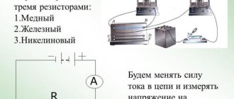
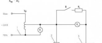
It was stated above that the resistance of conductors depends on temperature. Let's do the following experiment. Let's wind several meters of thin metal wire in the form of a spiral and connect this spiral to the battery circuit. To measure current, we connect an ammeter to the circuit. When the coil is heated in the burner flame, you will notice that the ammeter readings will decrease. This shows that the resistance of a metal wire increases with heating.
For some metals, when heated by 100°, the resistance increases by 40–50%. There are alloys that change their resistance slightly with heating. Some special alloys show virtually no change in resistance when temperature changes. The resistance of metal conductors increases with increasing temperature, while the resistance of electrolytes (liquid conductors), coal and some solids, on the contrary, decreases.
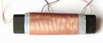
The ability of metals to change their resistance with changes in temperature is used to construct resistance thermometers. This thermometer is a platinum wire wound on a mica frame. By placing a thermometer, for example, in a furnace and measuring the resistance of the platinum wire before and after heating, the temperature in the furnace can be determined.
The change in the resistance of a conductor when it is heated, per 1 ohm of initial resistance and per 1° temperature, is called the temperature coefficient of resistance and is denoted by the letter α.
If at temperature t0 the resistance of the conductor is equal to r0, and at temperature t is equal to rt, then the temperature coefficient of resistance
Note. Calculation using this formula can only be done in a certain temperature range (up to approximately 200°C).
We present the values of the temperature coefficient of resistance α for some metals (Table 2).
table 2
Temperature coefficient values for some metals
| Metal | α | Metal | α | |
| Silver Copper Iron Tungsten Platinum | 0,0035 0,0040 0,0066 0,0045 0,0032 | Mercury Nikelin Constantan Nichrome Manganin | 0,0090 0,0003 0,000005 0,00016 0,00005 |
From the formula for the temperature coefficient of resistance we determine rt:
rt = r0 [1 ± α (t – t0)].
Example 6. Determine the resistance of an iron wire heated to 200°C, if its resistance at 0°C was 100 Ohms.
rt = r0 [1 ± α (t – t0)] = 100 (1 + 0.0066 × 200) = 232 Ohm.
Example 7. A resistance thermometer made of platinum wire in a room with a temperature of 15°C had a resistance of 20 ohms. The thermometer was placed in the oven and after some time its resistance was measured. It turned out to be equal to 29.6 Ohms. Determine the temperature in the oven.
Dimension[edit]
Main article: Ohmmeter
ohmmeter
A device for measuring resistance is called an ohmmeter. Simple ohmmeters cannot accurately measure low resistance because the resistance of their test leads causes a voltage drop that interferes with the measurement, so more accurate devices use four-prong measurement.
AC circuits [edit]
Impedance and tolerance
Main articles: Electrical impedance and conductivity
When alternating current flows through a circuit, the relationship between current and voltage on a circuit element is characterized not only by the ratio of their magnitudes, but also by their phase difference. For example, in an ideal resistor, at the moment when the voltage reaches its maximum, the current also reaches its maximum (current and voltage oscillate in phase). But for a capacitor or inductor, maximum current flows when the voltage passes through zero and vice versa (current and voltage oscillate 90° out of phase, see image below). Complex numbers are used to track the phase and magnitude of current and voltage:
u ( t ) = R e ( U 0 ⋅ ej ω t ) , i ( t ) = R e ( I 0 ⋅ ej ( ω t + φ ) ) , Z _ = U _ I _ , Y _ = I _ U _ {\displaystyle u(t)={\mathfrak {Re}}\left(U_{0}\cdot e^{j\omega t}\right),\quad i(t)={\mathfrak {Re} }\left(I_{0}\cdot e^{j(\omega t+\varphi )}\right),\quad {\underline {Z}}={\frac {\underline {U}}{\underline { I}}},\quad {\underline {Y}}={\frac {\underline {I}}{\underline {U}}}} Voltage (red) and current (blue) versus time (horizontal axis ) for the capacitor (top) and inductor (bottom). Since the amplitude of the current and voltage of the sinusoids are the same, the absolute value of the impedance is equal to 1 for both the capacitor and inductor (in any unit graph using). On the other hand, the phase difference between current and voltage for a capacitor is -90°; Thus, the complex phase of the capacitor impedance is -90°. Similarly, the phase difference between current and voltage is + 90 ° for an inductor; therefore, the complex phase of the inductor's impedance is +90°.
Where:
- t
time, - u (t)
and
i (t)
are voltage and current respectively as a function of time, - U 0
and
I 0
indicate the voltage amplitude of the corresponding current, - ω {\displaystyle \omega }—angular frequency of alternating current,
- φ {\displaystyle \varphi } displacement angle,
- U
,
I
,
Z
and
Y
are complex numbers, - Z
is called impedance, - Y
is called tolerance, - Re indicates the real part,
- j = − 1 {\displaystyle j={\sqrt {-1))} is the imaginary unit.
Impedance and conductance can be expressed as complex numbers, which can be broken down into real and imaginary parts:
Z _ = R + j X , Y _ = G + j B {\displaystyle {\underline {Z}}=R+jX,\quad {\underline {Y}}=G+jB}
where R
and
G
are resistance and conductance respectively,
X
is reactance, and
B
is conductance.
For ideal resistors, Z
and
Y
reduce to
R
and
G
respectively, but for AC networks containing capacitors and inductors,
X
and
B
are non-zero.
Z_=1/Y_{\displaystyle {\underline {Z}}=1/{\underline {Y}}} for AC circuits, as well as for DC circuits. R = 1 / G {\displaystyle R=1/G}
Frequency dependence
A key feature of AC circuits is that resistance and conductance can be frequency dependent, a phenomenon known as universal dielectric response. [8] One of the reasons mentioned above is the skin effect (and the related proximity effect). Another reason is that the resistance itself may depend on frequency (see Drude model, deep traps, resonant frequency, Kramers–Kronig relations, etc.)
Links[edit]
- ^ a b
Brown, Forbes T. (2006).
Dynamics of Engineering Systems: A Unified Graph-Oriented Approach
(2nd ed.). Boca Raton, FL: CRC Press. paragraph 43. ISBN 978-0-8493-9648-9. - ^ a b
Kaiser, Kenneth L. (2004).
Handbook of Electromagnetic Compatibility
. Boca Raton, FL: CRC Press. pp. 13–52. ISBN 978-0-8493-2087-3. - Fink & Beaty (1923). "Standard Guide for Electrical Engineers". Nature
(11th ed.).
111
(2788): 17–19. Bibcode: 1923Natur.111..458R. DOI: 10.1038/111458a0. hdl: 2027/mdp.39015065357108. S2CID 26358546. - Cutnell, John D.; Johnson, Kenneth W. (1992). Physics
(2nd ed.). New York: Wiley. item 559. ISBN. 978-0-471-52919-4. - McDonald, John D. (2016). Electric Power Substations Engineering
(2nd ed.). Boca Raton, FL: CRC Press. pp. 363ff. ISBN 978-1-4200-0731-2. - Battery Internal Resistance (PDF) (Report). Energizer Corp.
- "Electrocution Deaths of Workers" (PDF). National Institute for Occupational Safety and Health. Publication No. 98-131. Retrieved November 2, 2014.
- Zhai, Chunpu; Gan, Yixiang; Hanaor, Dorian; Proust, Gwenall (2018). "Voltage-dependent electric transport and its universal scaling in bulk materials." Letters on Extreme Mechanics
.
22
: 83–88. arXiv: 1712.05938. DOI: 10.1016/j.eml.2018.05.005. S2CID 51912472. - Ward, M. R. (1971). Electrical Engineering Science
. McGraw-Hill. pp. 36–40.