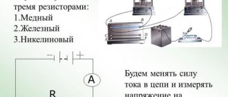
Electrical resistance of the wire
Any body through which electric current flows exhibits a certain resistance to it. The property of a conductor material to prevent electric current from passing through it is called electrical resistance.
The greater the resistance of a conductor, the worse it conducts electric current, and, conversely, the lower the resistance of the conductor, the easier it is for electric current to pass through this conductor.
The resistance of various conductors depends on the material from which they are made. To characterize the electrical resistance of various materials, the concept of so-called resistivity has been introduced.
Specific resistance is the resistance of a conductor with a length of 1 m and a cross-sectional area of 1 mm2. Resistivity is denoted by the letter p (rho) of the Greek alphabet. Each material from which a conductor is made has its own resistivity.
For example, the resistivity of copper is 0.0175, i.e. a copper conductor with a length of 1 m and a cross-section of 1 mm2 has a resistance of 0.0175 ohms. The resistivity of aluminum is 0.029, the resistivity of iron is 0.135, the resistivity of constantan is 0.48, and the resistivity of nichrome is 1-1.1.
The resistance of a conductor is directly proportional to its length, i.e. the longer the conductor, the greater its electrical resistance.
The resistance of a conductor is inversely proportional to its cross-sectional area, i.e. the thicker the conductor, the lower its resistance, and, conversely, the thinner the conductor, the greater its resistance.
The conductor resistance can be determined by the formula:
where r is the conductor resistance in (Ohm); ρ—conductor resistivity (Ohm*m); l is the length of the conductor in (m); S - conductor cross-section in (mm2).
Example: Determine the resistance of 200 m of copper wire with a cross section of 1.5 mm2.
Example: Determine the resistance of 200 m of copper wire with a cross section of 2.5 mm2.
Insulation
Insulation in electrical engineering is a design element of equipment that prevents the passage of electric current through it, for example, to protect people.
Materials with dielectric properties are used for insulation: glass, ceramics, numerous polymers, mica. There is also air insulation, in which air plays the role of an insulator, and structural elements fix the spatial configuration of the insulated conductors so as to provide the necessary air gaps.
Insulating covers can be produced:
- made of electrical insulating rubber;
- made of polyethylene;
- made of cross-linked and foamed polyethylene;
- from silicone rubber;
- made of polyvinyl chloride plastic (PVC);
- made of impregnated cable paper;
- made of polytetrafluoroethylene.
Rubber insulation
Rubber insulation can only be used with a rubber hose sheath (if available). Since rubber made from natural rubber is quite expensive, almost all rubber used in the cable industry is artificial. Add to rubber:
- vulcanizing agents (elements that allow the transformation of linear bonds in rubber into spatial bonds in insulation, for example, sulfur);
- vulcanization accelerators (reduce time consumption);
- fillers (reduce the price of the material without significantly reducing technical characteristics);
- softeners (increase plastic properties);
- antioxidants (added to shells for resistance to solar radiation);
- dyes (to give the desired color).
Rubber allows you to assign large bending radii to cable products, therefore, together with a stranded core, it is used in conductors for movable connections (cables of the KG, KGESH brand, RPSh wire). Specialization: used in general industrial cables for mobile connection of consumers.
Positive properties:
- low cost of artificial rubber;
- good flexibility;
- high electrical insulation characteristics (6 times higher than the value for PVC plastic);
- practically does not absorb water vapor from the air.
Negative qualities:
- reduction in electrical resistance when the temperature rises to +80°C;
- exposure to solar radiation (light oxidation) followed by characteristic cracking of the surface layer (in the absence of a shell);
- it is necessary to introduce special substances into the composition to obtain a certain chemical resistance;
- spreads the fire.
Electrical resistance and conductivity
CALCULATION OF THE SECTIONAL AREA OF WIRE DEPENDING ON THE LOAD POWER
Losses in conductors arise due to the non-zero value of their resistance, which depends on the length of the wire. The power values of these losses released in the form of heat into the surrounding space are given in the table. As a result, the voltage reaches the energy consumer at the other end of the wire in a slightly reduced form - less than it was at the source. The table shows that, for example, with a network voltage of 220 V and a 100-meter wire length with a cross-section of 1.5 mm2, the voltage at a load consuming 4 kW will be not 220, but 199 V. Is this good or bad? For some devices it doesn’t matter, some will work, but at reduced power, and some will kick up and send you to a hairdryer along with your long wires and smart tables. Therefore, the Ministry of Energy is the Ministry of Energy, and one’s own head will not hurt under any circumstances. If the situation develops in a similar way, there is a direct path to choosing wires with a larger cross-section.
The current strength in a conductor is directly proportional to the voltage across it.
Wire resistance.
This means that as the voltage increases, the current also increases. However, with the same voltage, but using different conductors, the current strength is different. You can say it differently. If you increase the voltage, then although the current strength will increase, it will be different everywhere, depending on the properties of the conductor.
The current versus voltage relationship for that particular conductor represents the resistance of that conductor. It is denoted by R and is found by the formula R = U/I. That is, resistance is defined as the ratio of voltage to current. The greater the current in a conductor at a given voltage, the lower its resistance. The greater the voltage for a given current, the greater the resistance of the conductor.
The formula can be rewritten in relation to current strength: I = U/R (Ohm's law). In this case, it is clearer that the greater the resistance, the less the current.
We can say that resistance prevents the voltage from creating a large current.
Resistance itself is a characteristic of the conductor. It does not depend on the voltage applied to it. If a large voltage is applied, the current will change, but the U/I ratio will not change, i.e. the resistance will not change.
What does the resistance of a conductor depend on? It's the envy of
- conductor length,
- its cross-sectional area,
- the substance from which the conductor is made,
- temperature.
To connect a substance and its resistance, the concept of specific resistance of a substance is introduced. It shows what the resistance will be in a given substance if a conductor made from it has a length of 1 m and a cross-sectional area of 1 m2. Conductors of the same length and thickness, made from different substances, will have different resistances. This is due to the fact that each metal (most often they are conductors) has its own crystal lattice, its own number of free electrons.
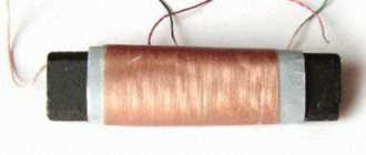
What is the resistance of copper wire
In metals, a current is formed when an electric field appears. It “forces” electrons to move in an orderly manner, in one direction. Electrons from the distant orbits of an atom, weakly held by the nucleus, form a current.
Copper wires
As negative particles pass through the crystal lattice of copper molecules, they collide with atoms and other electrons. There is an obstacle or resistance to the directional movement of particles.
To evaluate the resistance to current, the value of “electrical resistance” or “electrical impedance” was introduced. It is designated by the letter “R” or “r”. Resistance is calculated using Georg Ohm's formula: R=, where U is the potential difference or voltage acting on a section of the circuit, I is the current strength.
Concept of resistance
Important! The higher the impedance value of a metal, the less current passes through it, and it is copper conductors that are so widespread in electrical engineering due to this property. Based on Ohm's formula, the current value is affected by the applied voltage at constant R
But the resistance of copper wires varies, depending on their physical characteristics and operating conditions.
Based on Ohm's formula, the magnitude of the current is affected by the applied voltage at a constant R. But the resistance of copper wires varies depending on their physical characteristics and operating conditions.
S=(π?d^2)/4=0.78?d^2≈0.8?d^2
- where d is the diameter of the wire.
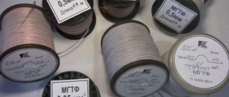
You can measure the diameter of the wire with a micrometer or caliper, but if you don’t have them on hand, you can tightly wrap about 20 turns of wire around a pen (pencil), then measure the length of the wound wire and divide by the number of turns.
To determine the length of wire needed to achieve the required resistance, you can use the formula:
1. If the data for the wire is not in the table, then some average value is taken. As an example, a nickel wire with a diameter of 0.18 mm, the cross-sectional area is approximately 0.025 mm2, the resistance of one meter is 18 Ohms, and the permissible current is 0.075 A.
2.The data in the last column, for a different current density, must be changed. For example, with a current density of 6 A/mm2, the value must be doubled.
Example 1. Let's find the resistance of 30 m of copper wire with a diameter of 0.1 mm.
Solution. Using the table, we take the resistance of 1 m of copper wire, which is equal to 2.2 Ohms. This means that the resistance of 30 m of wire will be R = 30•2.2 = 66 Ohms.
The calculation using the formulas will look like this: cross-sectional area: s = 0.78•0.12 = 0.0078 mm2. Since the resistivity of copper is ρ = 0.017 (Ohm•mm2)/m, we obtain R = 0.017•30/0.0078 = 65.50m.
Example 2. How much manganin wire with a diameter of 0.5 mm is needed to make a rheostat with a resistance of 40 Ohms?
Solution. Using the table, we select the resistance of 1 m of this wire: R = 2.12 Ohm: To make a rheostat with a resistance of 40 Ohms, you need a wire whose length is l = 40/2.12 = 18.9 m.
The calculation using the formulas will look like this. Cross-sectional area of the wire s= 0.78•0.52 = 0.195 mm 2. Wire length l = 0.195•40/0.42 = 18.6 m.
Temperature dependence ρ(T)
For most materials, numerous experiments have been carried out to measure resistivity values. Data for most conductors can be found in reference tables.
Specific resistance of metals and alloys, Ohm*mm2/m
(at T = 20C)
| Silver | 0,016 | Bronze (alloy) | 0,1 |
| Copper | 0,017 | Tin | 0,12 |
| Gold | 0,024 | Steel (alloy) | 0,12 |
| Aluminum | 0,028 | Lead | 0,21 |
| Iridium | 0,047 | Nickelin (alloy) | 0,42 |
| Molybdenum | 0,054 | Manganin (alloy) | 0,45 |
| Tungsten | 0,055 | Constantan (alloy) | 0,48 |
| Zinc | 0,06 | Titanium | 0,58 |
| Brass (alloy) | 0,071 | Mercury | 0,958 |
| Nickel | 0,087 | Nichrome (alloy) | 1,1 |
| Platinum | 0,1 | Bismuth | 1,2 |
Most often, the values of ρ are given at normal, that is, room temperature 20C. But it turned out that with increasing temperature, the resistivity increases linearly in accordance with the formula:
$ ρ(T) = ρ0 * (1 + α*T)$ (6),
where: ρ is the resistivity of the conductor at a temperature of 0C, α is the temperature coefficient of resistivity, which also has its own individual meaning for each substance. From formula (6) it follows that the coefficient α has dimension or .
Rice. 2. Temperature dependence of conductor resistivity
In accordance with the Joule-Lenz law, when an electric current flows, heat is released, which means the temperature of the conductor increases. In addition, depending on the area of application, electrical devices can operate at both low (minus) and high temperatures. For accurate calculations of electrical circuits, it is necessary to take into account the dependence ρ(T). The value of α for a specific material can be found in reference literature.
We advise you to study the Standards for electricity consumption per person without a meter
Rice. 3. Reference values of the temperature coefficient of resistivity of conductors