Home > Electrical wiring > Self-supporting insulated wire SIP 2
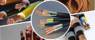
Self-supporting insulated wire (SIP) has found application primarily for supplying electricity from 10/0.4 kV transformer substations to consumers. The system appeared in the 60s of the last century as an alternative to bare wires on insulators.
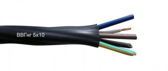
SIP-2 with a zero core (larger diameter), covered with insulation
The SIP-2 wire is part of a group of self-supporting insulated cables that transmit electricity through the air to various buildings. It is also used for external lighting networks. The wire can be used in ordinary, industrial and aggressive environments containing salt and moisture.
The photo above shows SIP-2 with a zero core covered with insulation.
Structure and characteristics of the neutral core
There are also other brands that differ in design:
- SIP-1 – the neutral conductor does not contain insulation (overhead power lines and branches to buildings);
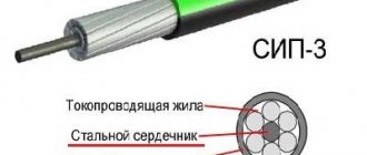
- SIP-3 – insulated wire with one core (for high-voltage lines);
- SIP-4 – there is no supporting conductor (2 or 4 twisted wires for branches).
Types of self-supporting insulated wire (SIP)
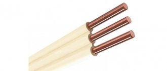
In the main wires, stranded and compacted conductors made of aluminum are covered with cross-linked polyethylene insulation, which can withstand weathering, ultraviolet radiation and prolonged heating up to 900C. They are wound on a zero core made of aluminum alloy. It can be without insulation (SIP-2, SIP-2F) or with it (SIP-2A, SIP-2AF). It is often reinforced with steel wire to increase structural rigidity. As shown in the figure, the steel core is located in the middle of the conductor.
Structure of the zero core SIP-2A
In this case, it is necessary that the resistance of the neutral core meets the standards given in the table.
Characteristics of the neutral core
| Core cross-section, mm2 | 25 | 35 | 50 | 54.6 | 70 | 95 |
| Resistance, Ohm/km | 1.38 | 0.986 | 0.72 | 0.63 | 0.493 | 0.363 |
| Number of wires | 2-7 | 2-7 | 2-7 | 2-7 | 2-7 | 2-7 |
| Minimum tensile strength, KN | 7.4 | 10.3 | 14.2 | 16.6 | 20.6 | 27.9 |
| Harness weight, kg/km | 670 | 770 | 907 | — | 1170 | 1265 |
The resistance of the phase conductors differs from zero. It can be found in the reference book for any brand of wire.
The table also shows the tensile strength of the zero core and the weight of the bundle, necessary for calculating the loads.
Design
1. The current-carrying conductor is aluminum, round in shape, all cross-sections are multi-wire compacted, the number of wires in the phase conductor. The outer diameter of the conductors and their electrical resistance are shown in the table:
| Nominal cross-section of phase conductor, mm2 | Number of wires in the core, pcs. | Outer diameter of current-carrying core, mm | Electrical resistance of 1 km of phase conductor to direct current, Ohm no more | |
| minimum | maximum | |||
| 16 | 7 | 4,6 | 5,1 | 1,910 |
| 25 | 7 | 5,7 | 6,1 | 1,200 |
| 35 | 7 | 6,7 | 7,1 | 0,868 |
| 50 | 7 | 7,85 | 8,35 | 0,641 |
| 70 | 7 | 9,45 | 9,95 | 0,443 |
| 95 | 7 | 11,1 | 11,7 | 0,320 |
| 120 | 19 | 12,5 | 13,1 | 0,253 |
| 150 | 19 | 14,0 | 14,5 | 0,206 |
| 185 | 19 | 15,45 | 16,15 | 0,164 |
| 240 | 19 | 17,75 | 18,45 | 0,125 |
2. The supporting zero core is made of aluminum alloy, round in shape, twisted from round wires, compacted, insulated. Nominal cross-sections, number of wires in the core, outer diameter of the cores, their tensile strength and electrical resistance are indicated in the table.
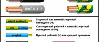
3. Insulation - made of light-stabilized cross-linked PE. Insulated phase conductors have a distinctive color. The insulation thickness is indicated in the table.
4. Twisting - insulated phase conductors are twisted around the zero load-bearing conductor. The twist of the cores is in the right direction. At the customer's request, it is possible to manufacture wires of the SIP-2 brand with an additional insulated conductor cross-section of 16 or 25 mm2 for connecting lighting circuits.
Advantages of SIP-2
- Possibility of use on common supports together with other wires.
- Reduced operating costs.
- Safety in case of accidental contact with live phase wires.
- The line remains operational even when the wires are jammed.
- Elimination of short circuits as a result of contact of a current-carrying wire with grounded elements.
- Structural simplicity and the ability to increase the distance between supports.
- Difficulty of unauthorized connection.
- There is no need to replace insulators. Possibility of repairing a live line.
- Inductive reactance is reduced by 2.5-3 times due to high-quality insulation.
Wire PV 3 1x6
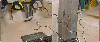
SIP can be used in conjunction with a traditional line. The figure shows a SIP branch (bottom) from a conventional air main on insulators.
SIP branch from the air main on insulators
Technical characteristics of SIP-2
The use of cross-linked polyethylene in the production of cables ensures its improved properties: strength, elasticity and heat resistance. SIP-2 is designed for the following temperature conditions:
- ambient temperature – from -600С to +500С;
- maximum operating temperature of the cable – 900C;
- limit value for overload (about 8 hours per day) – 1300C;
- heating of cores during short circuit (up to 5 sec.) – 2500C;
- permissible bending radius of the cable is at least 10 diameters.
The table shows the technical characteristics of the cable.
Characteristics of SIP-2
| № | Section | Harness diameter, mm | Harness weight, kg/km | Current strength in operating mode, A | |
| Phase wire | Lighting wire | ||||
| 1 | 3×25+54,6 | 24 | 531 | 112 | — |
| 2 | 3×25+54,6+16 | 25 | 600 | 112 | 83 |
| 3 | 3×25+54,6+2×16 | 26.5 | 670 | 112 | 83 |
| 4 | 3×35+54,6 | 24.6 | 641 | 138 | — |
| 5 | 3×35+54,6+16 | 25.5 | 710 | 138 | 83 |
| 6 | 3×35+54,6+2×16 | 27.5 | 779 | 138 | 83 |
| 7 | 3×50+54,6 | 27 | 770 | 165 | — |
| 8 | 3×50+54,6+16 | 28.5 | 839 | 165 | 83 |
| 9 | 3×50+54,6+2×16 | 30 | 907 | 165 | 83 |
| 10 | 3×70+54,6 | 30 | 985 | 180 | — |
| 11 | 3×70+54,6+16 | 32.2 | 1054 | 180 | 83 |
| 12 | 3×70+54,6+2×16 | 33 | 1122 | 180 | 83 |
| 13 | 3×95+70 | 35 | 1130 | 258 | — |
| 14 | 3×95+70+16 | 36 | 1200 | 258 | 83 |
| 15 | 3×95+70+2×16 | 37 | 1265 | 258 | 83 |
| 16 | 3×120+70 | 37 | 1380 | 300 | — |
| 17 | 3×120+70+16 | 38 | 1450 | 300 | 83 |
| 18 | 3×120+70+2×16 | 39 | 1520 | 300 | 83 |
| 19 | 3×150+70 | 40 | 1749 | 344 | — |
| 20 | 3×150+70+16 | 41 | 1817 | 344 | 83 |
| 21 | 3×150+70+2×16 | 42 | 1885 | 344 | 83 |
How to choose the right SIP-2 cable (cable cross-section)
The choice of wire cross-section is based on the current strength of the consumers, as well as possible overload currents. When taking into account overload capacity, the following standards should be taken into account:
- The duration of overloads should not exceed 8 hours a day;
- The total operating time with overload should not exceed 100 hours per month;
- The total operating time with overload for the full service life should not exceed 1000 hours.
The conclusion suggests itself is that to ensure uninterrupted and safe operation, you can use a wire with a larger cross-section. This is incorrect because it is not economically justified due to the high cost of the material.
A more complete and accurate calculation should take into account the type of cable insulation, since thermoplastic polyethylene has worse performance characteristics than cross-linked polyethylene, especially the permissible operating temperature (70°C versus 90°C).
The following is taken into account:
- The permissible load current of a wire with thermoplastic polyethylene insulation is 1.1 - 1.2 times less than that of cross-linked polyethylene.
- The cost of the latter is 1.3 – 1.4 times higher.
Thus, in many cases it is more advisable to use a thinner, but also more expensive wire with cross-linked polyethylene insulation. Reduced requirements for supports and fastening equipment (due to the lower mass of wires) and the higher durability of cross-linked polyethylene also contribute to the economic effect.
You may be interested in this Features of cable lugs
Price SIP-2
The cost per linear meter of cable varies widely. The base price is affected by the weight, cross-section and other parameters of the wire. The price of SIP-2 3x16 mm2 is currently 82 rub./m, and 3x70 mm2 – 254 rub./m. If the buyer orders a large quantity, it decreases. It will also be cheaper to buy pieces of wire from leftovers in the warehouse. If you need to unwind a short piece from a drum, the wire will be 3-5% more expensive, since the remainder will be shorter and more difficult to sell.
PuGV wire
A wire with a load-bearing core containing a steel core is more expensive. Also, the price is higher for a wire with an insulated load-bearing core (SIP-2A).
When purchasing, it is difficult to determine the length of the cable, since it is wound on a drum. Its calculated weight differs little from the actual one. If you determine the weight, you can easily find the length using the table.
Classification of SIP wires
In the modern market, sip wire is represented by the following classifications:
- system with a non-insulated load-bearing steel-aluminum core (SIP-1);
- systems with insulated load-bearing conductor (SIP-2);
- self-supporting insulated structures (SIP-3, SIP-4, SIP-5).
Let's take a closer look at each of the cable and wire products presented above.
Wire SIP-1: main characteristics and advantages
These systems are quite rarely used when installing overhead lines, since they have a high cost, low efficiency (technical characteristics) and are quite difficult to install. A wire of this brand is structurally made from a single or three-core (with a three-phase power supply system) current-carrying conductor, which envelops an uninsulated neutral along the entire length of the line.
As for the technical characteristics, this product can withstand temperatures up to 70° for a long time or a temperature of 125° for a short time. If the temperature is above the specified limits, the polyethylene, which acts as an insulating material, melts, thereby causing a short circuit between the bare and insulated conductors.
According to the requirements of PUE and GOST 50462–2009, these products have the same thickness of current-carrying phase conductors, and the supporting bare wire is made in such a way as to withstand high mechanical loads.
Important! Since in SIP-1 the neutral is made of a bare conductor, it must be grounded at each support to protect energy consumers and the system from phase imbalance.
SIP-2: main advantages, features and technical characteristics
This class of cable and wire products, unlike SIP-1, has insulation of absolutely all cores (including the neutral). If we consider the structural design, the SIP cable number 2 also consists of 1 or 4 current-carrying phase conductors and one insulated neutral conductor. In this case, the cross-section of the phase and neutral conductors may differ (for example, 4x25 + 1x35)
The SIP 2 wire has the following characteristics:
- insulation is made of cross-linked polyethylene (light-stabilized);
- nominal core cross-section from 16 to 120 mm²;
- the maximum permissible temperature of current-carrying conductors in long-term mode is 90 ° C;
- maximum permissible temperature in short-circuit mode should not exceed 250 °C;
- rated current ranges from 105 (1x16) to 340 A (3x120);
- The service life of this brand is 25 years.
SIP-3: features and description
SIP-3 is a self-supporting insulated wire that is capable of transmitting electricity over long distances. In these systems, all cores are completely insulated, and fastening to the supports occurs using special anchor clamps that securely fasten the zero load-bearing core.
These systems consist of 1 or 4 current-carrying conductors and are designed for installation in high-voltage lines (up to 20 kV). The design of the zero core in SIP-3 consists of several dozen cores (depending on the cross-section) that are twisted around a central steel wire.
The main advantage of this design over the previous two is its lower cost, since steel-aluminum alloy is not used here.
SIP-4 and SIP-5: characteristics, description and advantages
SIP wires of classes 4 and 5 are practically no different except for the insulation material. What does it mean? Thermoplastic polyethylene is used as insulation for phase and neutral conductors in SIP-4, which demonstrates ideal characteristics in regions with cold and temperate climates. Thanks to this insulation, the wire can withstand heat up to +50 °C and cold down to –60 °C.
The insulation thickness in products with the SIP-4 nomenclature ranges from 1.2 to 1.7 mm. This allows you to withstand temperatures up to 80° in long-term mode and 135° for 5 seconds when short circuit currents occur.
As for SIP-5, it can be called a modernized version of SIP-4. The main difference between these models is the type of insulation. Thus, SIP wire with number 5 is made of light-stabilized cross-linked polyethylene, which can withstand temperatures from 130 ° C during long-term heating and 250 in short-term heating when a short circuit occurs.
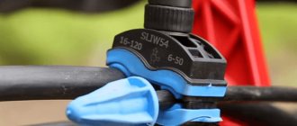
Fittings for SIP-2
- The load-bearing neutral is attached to anchor wedge clamps (if SIP-2A or SIP-2AF are used, the insulation is not removed). When installation is carried out, the cable is placed inside an aluminum alloy clamp and clamped with plastic wedges (Fig. a). Types of anchors: RA-1000, RA-1500, RA-2200.
- Prefabricated support clamps PS-1500 ES-1500 made of weather-resistant plastic are used for suspending wires on corner and intermediate supports (Fig. b). Complete with galvanized steel brackets, they form supporting units.
Wire PV 3
SIP fittings: a – anchor tension clamp; b – clamp for support; c – connecting clamps
SIP installation
- The basis for the wire are brackets attached to the supports with steel clamps.
- The installation work is mechanized. For wires with a cross-section of no more than 50 mm2, manual rolling of SIPs is allowed, since its low weight allows this to be done. A drum with a wire wound around it is placed near the support, to the end of which a rope is attached.
- Rollers for rolling are suspended at the top of each support. As installation proceeds, SIP is pulled along them using a rope. The wire should not be laid on the ground or in contact with the structure to avoid damaging the insulation.
- At the end of the section, the zero load-bearing core is secured with a clamp to the end support.
- The load-bearing core is pulled by a winch. The force is controlled by a dynamometer. After the wire hangs, it is checked for sag and finally tensioned.
- At the beginning of the section, the zero core is fixed with a clamp, after which the winch is removed.
- The neutral wire is transferred from the rollers to the supporting clamps. The unrolling rollers are removed.
- SIPs of adjacent sections of the line are connected by the bare ends of the wires by crimping in a sleeve (Fig. c).