Currently, the country's energy sector already has an idea of the problems that arose with the beginning of the mass use of single-phase 6-500 kV cables with cross-linked polyethylene (XPE) insulation.
To solve these problems, industry experts have found simple and convenient technical solutions. Mikhail DMITRIEV, chief specialist of VET PC “Sevzapenergosetproekt” OJSC “SevZapNTC”, St. Petersburg, Ph.D.
Let's consider one of the important issues of creating cable lines with single-phase cables - the selection and installation of grounding circuits for cable screens.
BASIC SCREEN CONNECTION DIAGRAMS
In Fig.
Figure 1 shows three basic diagrams for connecting and grounding screens of three-phase cable lines with single-phase cables. The circuits differ from each other in the currents and voltages induced on the screens, as well as in the power losses in the screens. The choice of the optimal grounding scheme is possible only after calculating all these quantities, for example, according to the method [1, 2]. In the diagram of Fig.
1a, the currents in the screens and the parasitic losses of active power caused by them are subject to calculation. In the diagrams of Fig. 1b,c there are no currents or losses in the screens, but it is necessary to check the voltage on the screen relative to the ground.
Design
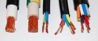
We’ve sorted out the approximate decoding of the markings, now let’s move on to considering the general design of armored cables. It consists of:
- A conductor made of aluminum or copper.
- A layer of insulation over the core, usually PVC, polyethylene or impregnated paper.
- Next comes a screen made of copper wires or various conductive tapes, for example, metal or conductive cardboard and paper.
- On top of the screen is another layer of insulation.
- Then comes a layer of armor, usually made in the form of tapes, then the top tape is applied so as to overlap the joints of the turns of the bottom tape. Tapes like a spiral on a cable.
- may in the center of the cable ; it can be a steel rope or a fiberglass rod, coated or uncoated. It plays a load-bearing role and relieves mechanical stress from the cores.
A special end coupling for an armored cable is installed at the end - it is needed to ensure that the layers of insulation and protection of the cable remain intact and safe, and the cores are separated from each other and reliably insulated.
End coupling, on the left you can see the grounding conductor for the armor, the conductors are separated and insulated, insulators are put on them
To connect building lengths of armored cables or connections during repair work in case of damage, they are also made in couplings, which are usually filled with bitumen or other dielectric solutions. More specifically, this point depends on what voltage the cable is designed for; the higher the voltage, for example 6-10 kV distribution networks, the more stringent the requirements for connections and insulation. At high voltages, the presence of air in the connection can be detrimental, as it ionizes, resulting in the development of discharges.
CALCULATION OF CURRENTS AND POWER LOSSES IN SCREENS
When calculating currents IE and losses PE in screens, an important role is played not only by their specific value, but also by how strongly they are noticeable against the background of currents IJ and losses PE in the cable core.
In Fig.
Table 2 for single-phase cables with screens grounded at both ends shows the results of calculations [1] of the relative values of currents induced in the screens IE / IZh for typical screen sections FE (from 25 to 240 mm2) depending on the ratio s/dE, in which: - the average distance between the axes of the three phases A, B, C;
— cable screen diameter; d — cable diameter according to the catalogue; ΔOB - the thickness of the cable sheath according to the catalog (almost always 5-6 mm). Using Fig. 2 it is easy to find the relative power losses: where are the linear active resistances of the core and screen; FZH, FE - sections of the core and screen; ρХ, ρЭ — resistivity of the material of the core and screen (for copper 2•10-8 Ohm•m, for aluminum 3.2•10-8 Ohm•m); LК – cable length, m.
Losses in a single-phase cable heat its insulation, the temperature of which should not exceed the permissible value for a long time. Therefore, it is obvious that in the absence of losses in the screens, the throughput current will be greater than in the case of the presence of such losses. The coefficient characterizing the degree of utilization of the cable's current carrying capacity, according to [1], is equal to The ratio PE/PJ of parasitic losses in the screen and inevitable losses in the core of single-phase cables is an important criterion for choosing a method for connecting their screens. The indicated ratio does not depend in any way on the length of the cable, and therefore it turns out that for a given type of single-phase cables and the method of laying them, special measures to combat currents in the screens are equally necessary for both short cables and long cables. At the same time, it is clear that the costs of implementing measures to combat losses in screens can be significant compared to the cost of a short cable, but are negligible compared to the price of a long cable. Therefore, it seems appropriate to introduce an additional criterion for choosing a method for connecting screens, which would take into account economic aspects. Let this be the cost of power losses in the screens.
Power losses in the screen of one phase PE (W) can be conveniently found as:
PE = (PE /PJ)•PJ, (3)
where PE / RZh are the relative losses in the screen according to (1); RZh = I2 Zh (R* Zh • LK) - power loss in the core of one phase (W); I Ж - average annual current in the core (A).
Cost of parasitic power losses for 1 year of cable operation:
C1year = W1year•C, (4) where C is the price of electricity losses rub./(kWh); — energy losses in the screens of three phases per year (kW•h)/year; 8760 is the number of hours in a year.
For all single-phase cables, regardless of their rated voltage class, it follows from (1) - (4) that an effective reduction in parasitic losses in screens and associated damage can be achieved:
- using cables with a small screen cross-section FE (with a large R* E);
- laying the cable phases in a closed triangle, since in this case the minimum s/dE ratio is achieved.
If laying the cable phases in a closed triangle does not reduce currents and losses in the screens to an acceptable level, then you should abandon the scheme of simply grounding the screens on both sides of the cable and move on to others:
- grounding of screens on one side (Fig. 1b);
- transposition of screens (Fig. 1c).
How to properly ground armor
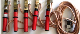
The armored cable is grounded using a flexible, uninsulated wire. At the same time, along the entire length of the line, the armor should not have breaks, that is, it should be solid. If there is a need to break the cable, for example, to repair it or to connect several sections, then the connection of the armor and the shell of the coupling is made with flexible stranded copper conductors. To select the wire cross-section for grounding, use the table:
Section of cable cores, mm Section of grounding conductor, mm up to 10 6 16, 25.35 10 50, 70, 95, 120 16 150, 185, 240 25
Grounding instructions
Clamp for fastening and grounding of metal pipes, metal hoses R3-TsH
When grounding an armored cable, the PUE recommends following the following rules:
- The grounding conductor is attached to the cable armor by soldering.
- First, this place is carefully tinned, after which a grounding conductor is soldered to it using a wire bandage with the obligatory use of soldering fat.
- To connect a copper tap without soldering, special clamps are used.
For these purposes, it is also possible to use spring-loaded connectors that guarantee reliable contact with the protective layer.
In the case of tape armor, the grounding wire is attached directly to its taps, and in the case of wire braided armor - around the circumference to all its conductors. When connecting sections of cable of standard length, sealed couplings of a special design are used. The connector set includes:
- local waterproofing elements;
- tips with special bolts;
- a grounding wire fixed to the armor of the connected areas;
- clamps for fastening wires with armor made of wire or steel tapes.
When cutting a cable before making a contact, the top insulating layer is removed to a length slightly longer than the braid located underneath it. In certain types of couplings, the manufacturer provides a special template that guarantees high-quality cutting of the entire product.
Standards of PUE grounding
Grounding PUE standards are a set of regulatory legal acts. These rules include recommendations on how to carry out electrical wiring correctly, a description of various electrical installations and the principle of their operation, as well as the requirements for electrical systems and their components.
Grounding installation work must be carried out in accordance with the electrical installation regulations.
The criteria defined in the PUE will allow all connections to be made without errors, maintaining all standards.
This guarantees reliable operation of the protective system in the house and will avoid the negative consequences of natural and man-made impacts.
If you unquestioningly follow all the rules described in the PUE, this will lead to large financial costs, so electricians and engineers follow only very important recommendations in their activities.
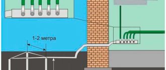
In accordance with the rules of the PUE, a repeated protective circuit must certainly be located at the exit areas from the premises.
It is recommended to install natural grounding electrodes at this location.
These include reinforced concrete devices, large metal parts, which for the most part are directly connected to the ground.
The PUE also specifies items that cannot be used as grounding conductors: energized metal objects, sewer and heating pipes, as well as pipelines with flammable substances.
When installing grounding, it is necessary to carefully carry out calculations, taking into account all the factors affecting the quality of the device being created, and it is necessary to follow the PUE.
Grounding resistance PUE
According to the PUE standards, all electrical appliances are manufactured in accordance with the standardized values:
- for telecommunications equipment, the protective device must have a resistance of no more than 2 Ohms or 4 Ohms;
- for reliable operation of a substation with a voltage of 110 kV, this indicator should be no more than 0.5 Ohm;
- when the power line voltage is 220V single-phase current source and 380V three-phase current, the resistance of the transformer substation must correspond to a value of no more than 4 Ohms;
- protective structures of overhead communication lines are connected to grounding with a resistance of no more than 2 ohms;
- when connecting lightning rods, the protective device must correspond to a resistance of no more than 10 Ohms;
- for private sector housing when operating the TN-CS system, a local grounding device with a resistance of no more than 30 Ohms is recommended;
- To connect private houses to a 220V/380V electrical circuit when operating the TT system using a residual current device, a protective grounding device with a resistance of no more than 500 Ohms is required.
Tethering an underground cable to the ground
To obtain high-quality grounding of the cable shield, PUE recommends adhering to the following rules:
- Cable armor and protective structures (structures) used for their installation should be connected to grounding elements of any type.
- The connection is formed due to reliable contact with the bare parts of metal pipes, reinforcing bars and other elements of natural grounding conductors.
- When organizing the power supply network in a private house, the armor of the introduced underground cable VbBShv is connected to a re-grounding device.
When wiring control and optical cables, it is mandatory to ground at least one of their ends.
For signal communication lines, grounding is done in order to reduce the influence of electromagnetic fields on the streams of transmitted data or to completely eliminate it. For particularly important areas of information exchange, a two-way ground fault is arranged. The screen of such cables is connected to the main distribution box of distribution boxes using copper conductors with a cross-section of at least 4 square meters. millimeters.
Don't miss: How to lay ceramic tiles: advice from professionals on laying chord cerama marazzi
Requirements for conductors
Minimum cross-section of protective conductors
When installing grounding, as well as protective grounding, steel cable sheaths of any class or armor are connected to the charger through copper conductors of a standardized cross-section. This requirement also applies to coupling or end coupling housings. On lines designed to transmit high-voltage power (6 kV and above) and having an aluminum sheath, coupling grounding is performed with separate conductors.
For this purpose, it is prohibited to use copper conductors with a conductivity greater than the corresponding indicator for cable sheaths.
The general requirements of current standards provide for the use of bare copper conductors with a cross-section of at least 6 mm square. The same parameters for control cables are specifically stipulated in the PUE (see clauses 1.7.76-1.7.78).
If the support of the air supply to the electrical installation is equipped with end couplings containing arresters, their housings are connected directly to the protective device charger. The use of cable sheaths alone in this capacity is not allowed in this situation. Special overpasses and galleries used to accommodate explosive cables must be equipped with protection against lightning discharges and lightning.
When moving from an underground laying line to a section of its overhead wiring and if the reinforced concrete support does not have its own charger, the couplings are allowed to be grounded to the cable armor. This approach is permissible only if the repair or extension coupling at the other end is connected to the station grounding circuit, or if the resistance value of the sheath of the grounded cable is sufficiently small.
When laying underground communications based on armored cable products, the efficiency of their operation largely depends on the quality of the grounding of the protective shell. When carrying out electrical installation work of any level of complexity, increased attention is paid to this issue.
CALCULATION OF VOLTAGE ON THE SCREEN RELATIVE TO GROUND
In [1] it was shown that the voltage on the screen is directly proportional to the current in the core IZ and the cable length LK. In addition, the screen voltage depends on:
- distance between phases s, screen diameter dE, ratio s/dE;
- equivalent depth of current flow in the ground DЗ, which is calculated as
where ρЗ is soil resistivity (Ohm•m);
μ0= 4π•10-7 - absolute magnetic permeability of vacuum (H/m); ω = 2πf - circular frequency of voltages and currents (rad/s). In Fig. Figures 3 and 4 present the results of calculations of voltage on the screen using the formulas from [1]. The voltage UE on the screen relative to the ground is determined for the current in the core I Ж = 1000 A and the cable length LК = 1000 m.
If the cable is laid in a switchgear, on the territory of an enterprise, etc., then the depth DZ is small (1, 3, 10 m) and is determined by the presence of a ground loop and various metal structures in the ground. In other cases, DZ depends on the soil resistance ρZ (10, 100, 1000 Ohm•m). Because of this, in Fig. 4 shows simultaneously the values of depth DЗ and resistance ρЗ.
With one-sided grounding of screens for arbitrary core current and cable length, the voltage at the grounded end of the screen can be found as:
where in normal mode or during an external three-phase short circuit of the network, the data in Fig. 3, and in case of an external single-phase short circuit of the network - the data in Fig. 4.
When transposing screens having N full cycles, the voltage at the transposition node can be found as:
where you should always use the data in Fig. 3, since for the transposition of screens a single-phase short circuit of the network is not a design case [1].
The voltage on the screen UE obtained as a result of calculations should not be more than the permissible values for the cable sheath, which are according to [1, 2]:
• in normal mode - 100 V; • in case of a short circuit in the network - 5000 V (this criterion is decisive).
Grounding a shielded cable
Grounding of cables is a mandatory procedure that is part of a set of measures for the construction of cable power and communication lines. Grounding is carried out in order to protect the cable itself and electrical equipment connected to the cable line from short circuit currents and various external influences (electromagnetic fields, lightning, stray currents, etc.). The second important purpose of constructing grounding systems is to protect people from electric shock.
There are many terms, definitions associated with grounding systems, as well as methods and methods of constructing them in relation to various cables, electrical installations, etc. - detailed information is given in Chapter 1.7 of PUE 7 (Electrical Installation Rules) dated 2002. Here we will discuss the main points of grounding shielded control cables, communication cables (including optical cables) and power cables.
Grounding of high-voltage power cables
Grounding of a shielded cable with a voltage of 6 kV and above can be done using a double-sided or one-sided screen grounding scheme. Both methods have their advantages and disadvantages. The advantage of double-sided grounding is ease of installation. It consists of connecting the screen to the ground loop - there is no need to use any additional tools or equipment. This grounding scheme assumes that the cable shield is at ground potential, which means that current occurs in a closed loop. This leads to significant power losses and a deterioration in the temperature conditions of the cable, which, in turn, may result in a reduction in its service life.
With one-sided grounding, only one end of the screen is connected to the grounding device. In this case, there is no path for currents to flow, which does not cause significant power losses. Minor losses may be observed due to the occurrence of eddy currents, but they do not determine the temperature regime and, as a result, do not reduce the service life of the cable.
However, the one-sided grounding scheme for a shielded cable requires the following factors to be taken into account:
• The occurrence of surge voltages can cause a decrease in the efficiency of the cable sheath. If the overvoltage value exceeds the electrical strength of the sheath, moisture may leak into the cable structure (for underground installation, as well as for cables without sealing). • This grounding scheme typically requires the use of additional equipment, including insulated shield terminations and protective devices installed at the ungrounded end of the cable shield. All this will require additional financial and labor costs when building a grounding system. • There is a risk of an induced potential (proportional to the current in the cable core) occurring at the ungrounded end of the shield, which may cause electric shock to operating personnel.
Thus, one-sided grounding requires the use of special equipment and the adoption of additional measures to ensure the safety of the cable line, which increases the cost of installation work and subsequent maintenance.
If the shielded cable is armored, then both of these components must be combined into a single circuit and then connected to the coupling housings. On cables with a voltage of 6 kV or more with an aluminum sheath, the connection of the sheath and armor to the ground is made using separate conductors (the cross-section of the conductors is selected according to the requirements given in sections 1.7.76–1.7.78 of the PUE).
When using a set of arresters on a structure support, the armor, shield and coupling are connected to the grounding device of the arrester. In this case, grounding only the metal shell is not allowed.
How to Ground a Shielded Control Cable
Grounding of control shielded cables and communication cables is carried out not only for safety purposes, but also to eliminate electromagnetic interference. Unlike power cables, control and communication cables also serve to transmit information or analog signals. The magnitude of electromagnetic interference can reach several kilovolts, the supply of which to the inputs of controlled electrical equipment can lead to a variety of consequences, including failure of the installations.
The shielded cable can also be grounded - either on one or both sides. However, in this case, preference is given to double-sided grounding of the screen. This circuit more effectively eliminates the influence of electric and magnetic fields of both high and low frequencies, preventing the accumulation of interference voltage above established standards.
As in the previous case, two-way grounding requires a special design approach. It is important to consider here that when there is a short circuit or lightning strike on the grounding device, there is a possibility of an increase in potential, which can lead to an increase in shield current and thermal damage to the cable. Various methods are used to reduce the potential: for example, by laying parallel grounding conductors along the cable or using closed grounding systems.
How to ground a shielded optical cable
According to RD 45.155, grounding of optical cables (OC) must be carried out at inputs to stationary structures, unattended regeneration points (URP) and any technical premises in which fiber-optic transmission lines (FOTL) are installed. The metal elements of the cable must be grounded - armor, metal sheath and/or cable (depending on the cable design).
Metal components of OK are connected to grounding devices with separate wires with a cross-section of at least 4 mm2. Special grounding panels installed in technical rooms are used as grounding devices. In the absence of shields, it is allowed to ground the metal components of the cable to special grounding terminals of the optical terminal devices (switches, servers, etc.).
is one of the leaders in the sale of cable products and has warehouses located in almost all regions of the Russian Federation. After consulting with the company’s specialists, you can purchase the brand of shielded cable you need at competitive prices.
EXAMPLE OF SELECTION OF SCHEME AND INSTALLATION OF SINGLE-SIDED GROUNDING OF SCREENS
Selection of scheme
A 110 kV cable line with a length LK = 600 m with a copper conductor FZh = 800 mm2 and a copper screen FE = 240 mm2 is laid in a closed triangle.
Normal mode current IZh = 1000 A, three-phase short circuit current 38 kA, single-phase short circuit current 42 kA.
It is necessary to select the optimal grounding scheme for the screens.
For cable 110 kV 800/240 according to the catalog, diameter d = 80 mm. With a typical shell thickness ΔOB = 5 mm, we find the screen diameter dE = d–2ΔOB = 70 mm. When laying in a triangle dAB = dBC = dAC = d, then the average distance between the phase axes is:
Ratio s/dE = 80/70 = 1.14.
According to Fig. 2 with s/dE = 1.14 and FE = 240 mm2 we have IE /IZh = 0.5.
By (1), (2) we find the relative losses and throughput: By (3), (4) we find the losses in the screens and their cost:
PE = (PE/RZh)• RZh = 0.83•(15•103) = 12.5•103 W;
where the cost of losses is taken equal to C = 1 rub./(kWh).
From the calculations it follows that when the screens are grounded on both sides, the cable capacity can be used only by 74% of its maximum value, and the cost of power losses in the screens is 330 thousand rubles. in year. Obviously, such a grounding scheme is unprofitable and unacceptable.
Let's consider one-sided grounding of screens. Comparing Fig. 3 and 4, it can be seen that the induced voltage with a single-phase short circuit is greater than with a three-phase short circuit. According to Fig. 4 with a typical soil resistivity ρЗ = 100 Ohm•m and a screen diameter dE = 70 mm, the voltage induced on the screen is UERIS = 650 V at 1000 A and 1000 m.
Using formula (5), with a single-phase short circuit current of 42 kA, we find the voltage on the screen:
which turned out to be significantly higher than the permissible value of 5000 V.
If, with one-sided grounding of screens in a network with a grounded neutral of 110-500 kV, as a result of calculations using formula (5), the screen-to-ground voltage turns out to be greater than the permissible value of 5 kV, then it is possible to provide for laying a special copper bus grounded at the ends along the cable. In [3] it is shown that the effect of its use is based on a decrease in the value of DZ included in the calculations, which, according to Fig. 4 will lead to a decrease in the induced voltage.
For example, according to Fig. 4 with a depth DZ = 1 m and a screen diameter dE = 70 mm, the induced voltage is UERIS = 200 V at 1000 A and 1000 m. Using formula (5) with a single-phase short circuit current of 42 kA, we find the voltage on the screen:
which is already acceptable.
So, for the 110 kV 800/240 cable line under consideration, we accept one-sided grounding of the screens. A copper conductive busbar, grounded at the ends, must be laid along the cable at a distance of no more than 1 m from it.
At the ungrounded end of the screen, to protect the cable sheath from surges between the screen and ground, surge arresters of 6 kV voltage class must be installed, as was shown in [1, 4].
Circuit installation
At the end of the cable where the screens are disconnected, a special three-phase end box (KK/OSN) is provided to accommodate screen surge arresters. For ease of installation and maintenance of the cable line, an end box (EC) that does not have an arrester and is called a grounding box is also installed at its opposite end (where the screens are solidly grounded without surge arresters).
At each end of the power cable, the screens are removed from the end coupling using a connecting wire with polyethylene insulation (PPS) and then go into the KK/OSP box, where they are connected to the surge arrester, or into the KK box, where they are connected to a busbar mounted on support insulators and grounded by a separate (already fourth) PPS wire.
The PPS wire has the same strength as the sheath of the power cable (insulation class 6 kV), and its cross-section is taken equal to the cross-section of the power cable screen (in this example - 240 mm2).
As an example, consider the installation of a CC box without surge arresters (Fig. 5-10):
• rice. 5 — remove the cover from the box and install the box at the place of use; • rice. 6 - on the bottom panel, use a knife to cut the silicone seal to a diameter that corresponds to the diameter of the PPS wire; • rice. 7 — cut the PPS in accordance with the sizes of the tips that come with the box; • rice. 8 — put a heat-shrinkable tube (HERE) on the PPS, then crimp the tip onto the cut end of the PPS wire; • rice. 9 — put the tip on the surge arrester stud and secure it with a nut, then heat-shrink the tube HERE with a heat gun or gas torch; • rice. 10 - perform the operations shown in Fig. 6-9, for the remaining wires of the PPS and then close the box with a lid.
What is the purpose of grounding?
Cable shield grounding is used to protect equipment. With the help of this operation, devices, tools, instruments, equipment are protected from electromagnetic radiation and various types of other interference.
Obstacles to the normal operation of equipment are created by:
short circuit currents; lightning strikes; switching in low-voltage and high-voltage networks; power units; discharges of static electricity; radio transmitting devices.
The grounding procedure reduces the touch voltage to a safe value. Not only various equipment, but also people and animals are removed from possible damage.
Screen grounding eliminates the flow of currents generated by parasitic feedback. This type of communication can operate in phase. The result is that 2 conductors use amplification of the input signals. Grounding the screen neutralizes this undesirable phenomenon.
In many countries, general requirements for grounding and its specific implementation are regulated by approved rules (PUE - “Rules for the construction of electrical installations”). To regulate safe operation processes, technical regulations and separate legislative norms are applied.
EXAMPLE OF SELECTION OF SCHEME AND INSTALLATION OF SCREEN TRANSPOSITION
Selection of scheme
A 10 kV cable line with a length LK = 6000 m with a copper conductor FZh = 630 mm2 and a copper screen FE = 95 mm2 is laid in a closed triangle.
Normal mode current IZh = 700 A, three-phase short circuit current 20 kA, single-phase ground fault current is unimportant, since it does not affect the calculations.
It is necessary to select the optimal grounding scheme for the screens.
For cable 10 kV 630/95 according to the catalog, diameter d = 50 mm. With a typical shell thickness ΔOB = 5 mm, we find the screen diameter dE = d–2ΔOB = 40 mm.
When laying in a triangle dAB= dBC= dAC= d, then the average distance between the phase axes
Ratio s/dE = 50/40 = 1.25.
According to Fig. 2 with s/dE = 1.25 and FE = 95 mm2 we have IE /IZh = 0.25.
Using formulas (1), (2) we find the relative losses and throughput: where the cost of losses is taken equal to C = 1 rub./(kWh).
From the calculations it follows that when the screens are grounded on both sides, the cable capacity can be used only by 84% of its maximum value, and the annual cost of power losses in the screens is 990 thousand rubles per year. Obviously, such a grounding scheme is unprofitable and unacceptable.
It is clear in advance that for a line 6000 m long, one-sided grounding of the screens is not suitable. Therefore, we consider one complete cycle of transposition of N = 1 screens.
In 6-35 kV networks with an isolated neutral, when determining the voltage on the screen, a three-phase short circuit is calculated. According to Fig. 3 at s/dE = 1.25. the induced voltage is UERIS = 50 V at 1000 A and 1000 m.
Using (6), with a single-phase short circuit current of 20 kA, we find the voltage on the screen: which is less than the permissible value of 5000 V (if the voltage were greater than the permissible value, then the calculations would have to be repeated for N = 2, 3...).
So, for the 10 kV 630/95 cable line under consideration, we accept one full cycle of screen transposition N = 1. If it is not possible to place screen transposition points at marks 1/3 and 2/3 of the cable route, then it is necessary to carry out calculations using the method [ 5] to those conditions of transposition that are realizable.
In screen transposition nodes, to protect the cable sheath from surges between the screen and ground, arresters of 6 kV voltage class must be installed, as was shown in [1, 4].
Circuit installation
To place the surge arrester in the transposition units, a special transposition box (KT/ surge arrester) is installed in the so-called transposition well (as a rule, this is a reinforced concrete well of the KKS-5 type). The power cable shields are removed from the transposition couplings of phases A, B, C of the cable using connecting wires with polyethylene insulation (PPS) and then enter the CT/OSP, where they are connected to the surge arrester.
The PPS wire has the same strength as the sheath of the power cable (insulation class 6 kV), and its cross-section is taken equal to the cross-section of the power cable screen (in this example - 95 mm2).The sequence of installation of the transposition box, which does not require opening it and breaking the seal, is as follows (Fig. 11-18):
• rice. 11 — prepare the box for installation (install in the transposition well); • rice. 12 - cut the PPS wire, removing the insulation from it to the required length, then put on the thermofit heat-shrinkable tube; • rice. 13 — insert the protected end of the PPS into the bushing and tighten the screws using a hexagon socket wrench; • rice. 14 - wrap the PPS wire using “adhesive tape 23” in two layers, starting from the skirt of the bushing; • rice. 15 — push the thermofit heat-shrinkable tube onto the skirt of the bushing until it stops; • rice. 16 — perform heat shrinking of the “thermofit” tube using a heat gun or a gas burner, starting from the skirt of the bushing; • rice. 17 - complete heat shrinking; • rice. 18 - perform the operations shown in Fig. 12-17, for the remaining wires of the PPS and then close the cover of the transposition well.
Laying armored cables in the ground
Laying cables in armor in different types of soil has its own characteristics. In places with unstable soils, in rocky formations and in permafrost areas, a cable with wire armor is laid, and in places with a stable type of soil - with tape armor. When laying, it is necessary to ensure that the protective sheath does not have electrical breaks along its entire length. The armor is grounded using a flat, uninsulated wire. The required cross-section of the grounding wire is given in the table:
Don't miss: Bathtub and tile joint. How to seal the joint between the bathtub and the tiles
How to ground cable armor
For installation in difficult conditions and to protect the electrical line from damage, armored cables are used, representatives of which are VBBbShv and AVBbShv. Armored is an electrical cable protected by a layer of metal tapes or layers of metal wire. Definitions of names and types of cable products and related terms are described in GOST 15845-80. A prerequisite for its use is the grounding of the armor, since current standards and requirements indicate the need to ground all conductive parts of the electrical installation. In this article we will look at how to ground an armored cable.
LITERATURE
1. Dmitriev M.V.
Grounding of screens of single-phase power cables 6-500 kV. - St. Petersburg: Polytechnic Publishing House. Univ., 2010. -152 p. 2. STO 56947007-29.060.20.103-2011. Power cables. Methodology for calculating screen grounding devices, surge protection for insulating power cables for voltages of 110–500 kV with cross-linked polyethylene insulation.
3. Dmitriev M.V., Kiyatkina M.R. Efficiency of using a metal busbar parallel to single-phase cables. // Energetik, No. 6, 2012, p. 20—22.
4. Dmitriev M.V. Overvoltages on the insulation of screens of single-phase power cables 6-500 kV and protection against them. // CABLE-news, No. 11, November 2008, p. 56-62.
5. Dmitriev M.V., Kiyatkina M.R. Transposition of cable screens 6-500 kV. Practical aspects of use // News of Electrical Engineering, No. 2(74), 2012, p. 80-84.
