Characteristics of grounding devices.
When live parts are shorted to ground, an electric current passes through the fault. Depending on the magnitude of this current, electrical installations with small and large ground fault currents are distinguished. If in an electrical installation with a voltage above 1000 V, the single-phase ground fault current is equal to or less than 500 A, it is considered an installation with low ground fault currents. If the specified current is greater than 500 A, the installation is considered to have high ground fault currents. The permissible resistance value of grounding devices for the specified installations is assumed to be different. Thus, for installations with low ground fault currents, the resistance of the grounding device at any time of the year should not exceed 10 Ohms and, in addition, be no more than Ohms when used only for installations above 1000 V and no more than Ohms when using a grounding device also for installations with voltages up to 1000 V. In the given expressions, the calculated ground fault current (A). In installations with large ground fault currents, the maximum permissible resistance value of grounding devices is 0.5 Ohm. The standard for the resistance of grounding devices of power transmission line supports with voltages above 1000 V is set depending on the resistivity of the earth. These standards are given below.
| Earth resistivity, Ομ m | Grounding device resistance, Ohm |
| up to 100 | to 10 |
| from 100 to 500 | » 15 |
| » 500 » 1000 | » 20 |
| more than 1000 | » 30 |
For electrical installations with voltages up to 1000 V, operating with a solidly grounded neutral, for generators and transformers with a power of 100 kVA or less, the resistance of the grounding devices should not be more than 10 Ohms, and with a power of the latter above 100 kVA - no more than 4 Ohms. When operating generators and transformers in parallel, their total power is taken into account. Grounding devices for overhead lines with voltages up to 1000 V, intended for protection against atmospheric surges, must have a grounding resistance of no higher than 50 Ohms.
- Back
- Forward
Our company offers materials for grounding various types of substations. Basic regulatory references for grounding devices.
RULES FOR ELECTRICAL INSTALLATIONS, Seventh Edition Grounding devices of electrical installations with voltage up to 1 kV in networks with a solidly grounded neutral
"1.7.100. In electrical installations with a solidly grounded neutral, the neutral of a three-phase alternating current generator or transformer, the midpoint of a direct current source, one of the terminals of a single-phase current source must be connected to the grounding conductor using a grounding conductor. An artificial ground electrode designed to ground the neutral, as a rule, should be located near the generator or transformer. For intra-shop substations, it is allowed to place the ground electrode near the wall of the building.”
"1.7.101. The resistance of the grounding device to which the neutrals of a generator or transformer or the terminals of a single-phase current source are connected, at any time of the year should be no more than 2, 4 and 8 Ohms, respectively, at line voltages of 660, 380 and 220 V of a three-phase current source or 380, 220 and 127 In a single-phase current source."
"1.7.111. Artificial grounding conductors can be made of black or galvanized steel or copper."
Table 1.7.4
The smallest dimensions of grounding conductors and grounding conductors laid in the ground
| Material | Section profile | Diameter, mm | Cross-sectional area, mm | Wall thickness, mm |
| Black steel | Round: | |||
| for vertical grounding conductors | 16 | — | — | |
| for horizontal grounding conductors | 10 | — | — | |
| Rectangular | — | 100 | 4 | |
| Angular | — | 100 | 4 | |
| Pipe | 32 | — | 3,5 | |
| Galvanized steel | Round: | |||
| for vertical grounding conductors | 12 | — | — | |
| For horizontal grounding conductors | 10 | — | — | |
| Rectangular | — | 75 | 3 | |
| Pipe | 25 | — | 2 | |
| Copper | Round | 12 | — | — |
| Rectangular | — | 50 | 2 | |
| Pipe | 20 | — | 2 | |
| Multi-wire rope | 1,8* | 35 | — |
* Diameter of each wire.
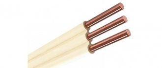
We propose to consider the installation of a grounding device for PTS. The main material, also known as the vertical grounding conductor, is a steel rod coated with a layer of copper using an electrochemical method. The copper layer is at least 250 microns.
The rod is threaded on both sides.
The vertical ground electrode is driven into the ground. The length of one copper-plated rod is 1.2 meters. Using a brass coupling, the rods are mechanically connected, thus increasing the length (depth) of the ground electrode. This installation method and these materials are effective in limited installation conditions. This technology makes it possible to achieve current flow resistance in the range from 1 to 4 ohms.
To install the grounding of the KTP, 10 rods, 10 couplings, a tip for the first rod, and an impact-receiving head for transmitting the impact from the vibrating hammer to the rods were needed. The grounding conductor is a steel strip measuring 40x4 mm, galvanized 3 meters.
Tools: - jackhammer with attachment for driving rods; — SDS-MAX hammer drill with a drill with a diameter of 26 mm and a length of 1 meter; — angle grinder; - pipe wrenches; — wrenches 13; — 50 m extension cord for powering power tools.
The first thing required is to determine the installation location. It is necessary to make sure that there are no communications, power cables or any building structures (concrete foundations) passing through this area.
Using an SDS-MAX hammer drill and a drill with a diameter of 26 mm, we go through the asphalt layer and gravel substrate.
Let's assemble the first rod. We screw the driving tip onto one side and onto the second coupling. We screw the shock-receiving head into the coupling. We insert the assembled rod into the drilled hole.
To hammer in vertical rods we use a jackhammer with an impact force of 20 J and an SDS-MAX adapter. With the other end we insert the nozzle into the shock-receiving head.
We hammer in the first rod so that the coupling is higher than the hole in the asphalt. Unscrew the impact head. Fill with conductive liquid. Install the next rod. We screw the rod into the coupling, holding it with a pipe wrench. Tightening is carried out until a characteristic creak occurs. We install the impact-receiving head on the upper end and continue hammering.
The first few rods are usually driven in with some ease, because... The top layer of soil is not so dense. We hammer in all the rods, leaving 15 cm at the last one for connecting the clamp. The clamp is made of stainless steel and is tightened with 4 bolts.
10 rods for this PTS gave 3.37 ohms, which satisfies the requirements.
Next, you need to connect the grounding conductor to the vertical ground electrode through the clamp. As a result, the entire connection is wrapped with a special insulating tape, which will form an insulated cocoon to protect it from water and dirt.
The time spent on the entire installation of the KTP grounding device was 1.5 hours, taking into account electrical measurements and connection to the KTP GZSh. The cost of such a kit was 15 thousand rubles.
This installation method and original materials are applicable in particular to substations for various purposes, because There is not always space to install a large circuit with several grounding electrodes.
Repair of high-speed devices
Repair of any type of high-speed protective device must be performed in the same sequence. The high-speed switch, or BV, is purged with clean compressed air under a pressure of no more than 300 kPa (3 kgf/cm2). After this, the device is wiped with napkins. Next, it is necessary to remove such elements as the arc chute, blocking device, pneumatic drive, armature with moving contact, inductive shunt and others.
Direct repair of the device is carried out at a special repair stand. The arc chamber is disassembled, its walls are cleaned in a special shot blasting unit, after which they are wiped and inspected. Chips may be allowed in the upper part of this chamber if their dimensions do not exceed 50x50 mm. The thickness of the walls at the break points should be from 4 to 8 mm. It is necessary to measure the resistance between the horns of the arc chute. For some samples, the indicator should be at least 5 MOhm, and for some, at least 10 MOhm.
The damaged partition must be cut down along its entire length. All similar areas of log houses must be thoroughly cleaned. After this, the surfaces to be glued are lubricated with an adhesive solution based on epoxy resin. If broken fan sheets are found, they are replaced. If they are bent, they must be straightened and returned to service. There is also an arc extinguishing coil, which must be cleaned of carbon deposits and melts, if any.
Thermal and current relay
Today, among electrical network protection devices there are many different types of relays.
A thermal relay is one of the most common devices that can protect electric motors, heaters, and any power devices from problems such as overload current. The operating principle of this device is very simple, and it is based on the fact that electric current is capable of heating the conductor through which it flows. The main working part of any thermal relay is a bimetallic plate. When heated to a certain temperature, this plate bends, which breaks the electrical contact in the circuit. Naturally, the plate will heat up until it reaches a critical point.
In addition to thermal ones, there are other types of protection devices, for example a current relay, which controls the amount of current in the network. There is also a voltage relay that will respond to changes in voltage in the network and a differential current relay. The last device is a leakage current protection device
It is important to note here that circuit breakers, like fuses, cannot react to the occurrence of current leakage, since this value is quite small. But at the same time, this value is quite enough to kill a person upon contact with the body of a device susceptible to such a malfunction
If there are a large number of electrical devices that need to be connected to a differential current relay, then combined circuit breakers are often used to reduce the size of the power panel. Such devices are devices that combine a circuit breaker and a differential current relay - differential protection circuit breakers, or differential circuit breakers. When using such devices, not only the size of the power shield is reduced, but also the process of installing the protection device is greatly simplified, which, in turn, makes them more economical.
Purpose of grounding and basic definitions.
During the operation of rural electrical installations (stations, substations and power lines), there may be cases of people and animals touching live parts of the installations that are energized. Touching parts that are not normally under voltage, but which become under it due to a breakdown of the insulation of these parts, cannot be ruled out. In both cases, an electrical current will pass through the body of people and animals, which can be fatal. To protect people and animals from the danger of electric shock, grounding is provided, i.e., connecting the bases and metal casings of electrical equipment to the ground. Grounding is also performed to ensure normal operating conditions of the electrical installation and to divert lightning discharges into the ground. According to their purpose, protective, working and lightning-protective grounding are distinguished. Protective grounding is performed in order to ensure adequate safety of people and farm animals from electric shock in the event of violations of the insulation of electrical installation elements. Working grounding (for example, grounding of the neutral of transformers with a voltage of 110 kV) ensures a certain operating mode of the electrical installation, and lightning protection provides lightning current drainage from rod and cable lightning rods and arresters. In general, grounding is understood as the intentional connection of electrical installation elements with a grounding device consisting of grounding conductors and grounding conductors. A ground electrode is a metal conductor or group of electrically connected conductors in direct contact with the ground. Their purpose is to provide an electrical connection to the ground. Grounding electrodes can be natural or artificial. Grounding conductors are metal conductors connecting the grounded parts of an electrical installation and equipment housing with a ground electrode. Underground water pipes and metal structures of buildings and structures that have a good connection to the ground can be used as natural grounding conductors in installations with voltages up to 1000 V. Artificial grounding conductors are made in the form of steel rods of round or flat cross-section. The material for single ground rods can also be angle steel. Damage to the insulation of an electrical installation can cause a ground fault and a frame fault. A ground fault is an accidental short circuit (connection) of energized live parts of an installation directly to the ground. A short-circuit to the frame is the electrical connection of live parts of an electrical installation with grounded bases and housings of electrical equipment. All housings of electrical machines, transformers, switches, devices and drives to them, secondary windings of instrument transformers, frames of distribution boards, cabinets and control panels, metal structures of substations and distribution devices, metal shells of power cables and cable coupling housings, arresters, spark arresters are subject to grounding. gaps, lightning rods and cables on each support.
TN-C
Today, all modern residential and non-residential buildings are equipped with the TN-S grounding system. Unfortunately, this scheme is used only at facilities that were commissioned no earlier than 15–20 years ago. The vast majority of housing built during the USSR are equipped with a TN-C system. This does not mean that all these facilities were built in violation of SNiP. It’s just that in those days, the standards (including PUE) were different.
Ideally, all existing networks should be upgraded to the TN-S standard. But this will require huge capital investments. In addition, laying additional ground lines from supply substations is not always technically possible. This means that in some places the entire network of power cables will have to be changed.
Grounding TN-C does not provide complete safety for the following reasons:
“Ground” and working zero represent one line, which is located in the power cable from the power source to the consumer. The ground electrode (ground loop physically connected to the ground) is located in close proximity to the supply substation. This method of organizing grounding is called a solidly grounded neutral. The power cable consists of four cores: three phases (L1, L2, L3), and a working neutral combined with a working ground (PEN).
Since the working zero is under load (an active electric current flows through it), it is in the so-called risk zone. There are often cases when this conductor simply burns out due to overheating. Let us leave what happens to the end consumers out of the picture - the voltage can jump to 600 volts. The main danger is that all electrical installations in this case lose their protective grounding. By touching the housing, which may contain phase potential, a person is guaranteed to be shocked by an electric shock. A particular danger in such an accident is simultaneous touching of an electrical installation that is energized and metal structures that have physical contact with the ground: heating systems, plumbing, fittings in the walls. Even a wet cement floor connected to reinforcement in a screed can cause a tragedy.
In apartment buildings and other facilities equipped with a TN-C system, there is generally no protective grounding in the usual sense. Everyone knows what Soviet-style sockets look like: they do not have grounding contacts. Even if owners replace them with three-pin modern sockets, the protective grounding terminal remains unclaimed: there is simply nothing to connect it to.
For this reason, at facilities equipped with TN-C grounding, in rooms with high humidity (bathrooms, baths, laundries), it is prohibited to use ungrounded electrical appliances. If you are installing a boiler or a washing machine, connecting it to grounding (or organizing an additional potential equalization system) based on the working neutral is prohibited!
It is necessary to organize a ground electrode (a complete circuit that has physical contact with the ground). Moreover, the parameters of such a grounding conductor must comply with the requirements of the Electrical Installation Rules.
A metal corner 50 cm long, driven into the front garden at the entrance, is not a grounding conductor!
Then a grounding conductor (with a cross-section of at least 2.5 mm², and without disconnectors along its entire length) is brought into the apartment, which is connected directly to the electrical installation. Of course, it is necessary to install a grounding shield or terminal block, connect sockets and housings of dangerous electrical appliances to it.
Types of memory
Objects of both artificial and natural origin can be used as grounding devices. The first of them are presented:
- steel scraps of pipes and rails;
- metal cables and chains;
- long steel rods (diameter - 1 cm);
- steel strips or angle steel at least 2 meters long;
- steel pipes with a diameter of 3 cm.
It is worth noting that the resistance of grounding devices can only be determined by carrying out control measurements. If the natural element shows an acceptable R-value, then no additional structures will be needed. Natural objects are represented:
- lead cable sheaths;
- underground pipes of residential premises that connect to the ground;
- reinforced concrete foundation if there is moist soil around (loam or clay);
- underground pipes (the only exceptions are heating mains and those through which flammable materials are transported).
Arrangement in a private house
Some owners of country houses often wonder whether grounding is necessary in a wooden house? The answer to this can be found in the main provisions of the current regulations (in the PUE, for example), where the specified protective measure is stipulated as mandatory.
Moreover, it turns out that making a reliable grounding structure in a private house is much easier than in a city apartment building.
Indeed, to arrange grounding in a countryside area, it is enough to choose a place convenient for placing the ground electrode not far from the house and connect a copper busbar to it.
It is not possible to do this in urban conditions, since the presence of a reliable grounding system within the boundaries of the house is not provided for by building regulations (SNiP).
In this situation, one can only be content with grounding on the side of the supply substation, which is remote over considerable distances and for this reason does not provide the required protection efficiency.
Quite often, suburban farms use power equipment operating from a three-phase power source, the effective grounding of the supply circuits of which is considered mandatory.
What is the ground loop made of?
- 24 May 2021 09:08:49
The questions about what grounding, a grounding loop and a grounding device are are answered by PUE 7. This set of rules, which guide design engineers in their work, defines artificial grounding
as a specially organized electrical connection between a grounding device and a specific point in the network, equipment or electrical installation.
The electric current is diverted into the ground and dissipates in it without causing harm to people - the value of the touch voltage thanks to the ground electrode is reduced to a level that is safe for humans. The safety of operating conditions for electrical equipment is determined by the presence of a functioning, efficient grounding. The grounding device
directly includes a ground electrode and a conductor.
The grounding conductor
conducts electric current into the ground, and the grounding conductor connects it and the protected object. Despite the common goal, the design features and operating mechanisms of different types of grounding devices differ significantly.
Disadvantages of different types of protective devices
Fuses, which were previously widely used as devices for protecting switchgear, have the following number of disadvantages:
- rather limited possibility for use as protection against overload current, since detuning from inrush currents is quite complicated;
- the electric motor will continue to operate on two phases, even if the third is cut off by the fuse, which is why the motor often fails;
- in certain cases the cut-off power limit is insufficient;
- There is no way to quickly restore power supply after a power outage.
As for air type circuit breakers, they are more advanced than fuses, but they are not without drawbacks. The main problem with using electrical protective devices is that they are not selective in terms of action. This is especially noticeable if an unregulated cut-off current occurs at the installation machine.
There are automatic installation machines in which overload protection is carried out using thermal releases. Their sensitivity and delay are worse than those of thermal relays, but at the same time they act on all three phases at once. As for universal automatic machines for protection, here it is even worse. This is justified by the fact that only electromagnetic releases are available.
Magnetic starters with built-in thermal relays are often used. Such protective equipment is capable of protecting an electrical circuit from overload current in two phases. But since thermal relays have a large inertia, they are not able to provide protection against short circuits. If you install a holding coil in the starter, you can provide undervoltage protection.
High-quality protection from both overload current and short circuit can only be provided by inductive relays or electromagnetic relays. However, they can only operate through a disconnecting device, which makes their connection circuit more complex.
To briefly summarize the above, we can draw the following two conclusions:
To protect electric motors, whose power does not exceed 55 kW, from overload current, magnetic starters with fuses or with air devices are most often used. If the power of the electric motor is more than 55 kW, then electromagnetic contactors with air devices or protective relays are used to protect them
It is very important to remember here that the contactor will not allow the circuit to break if a short circuit occurs
When selecting the right device, it is very important to calculate the protection devices. The most important formula is the calculation of the rated current of the motor, which will allow you to select a protective device with suitable indicators
The formula looks like this:
Iн=Рдв ÷(√3*Un*cos c*n), where:
Iн is the rated current of the motor, which will have the dimension in A;
Rdv is the engine power, which is represented in kW;
Un is the rated voltage in V;
cos c is the active power factor;
n is the efficiency factor.
Knowing these data, you can easily calculate the rated current of the motor, and then easily select a protective device suitable for its intended purpose.
Electric motor installation technology
The engine can be delivered to the installation site directly from the manufacturer, from the warehouse and after repair work. It can be installed on a steel or cast iron plate, a welded metal frame, a special slide or bracket. All these elements must be aligned along the axes of the engine installation in a horizontal plane and secured with foundation bolts. Holes for them are usually made during construction work, if this is provided for in the working design. In this case, plugs made of wood are left in the required places in advance.
If this is not provided for by the project, then markings are first carried out according to the installation and installation dimensions, which are specified in the manufacturer’s instructions. Then holes of the required diameter are punched using pneumatic or electric hammers. It is also necessary to measure the height to the axis of the engine shaft in order to determine the thickness of the lining installed under the paws. It should not exceed 5 mm. This is the only way to ensure correct alignment of the electric motor. The reliability of the product depends on this indicator. Currently, shaft alignment is performed using laser systems, which allows alignment with a high degree of accuracy, which will affect the service life.
If engines have a V-belt or belt drive, a necessary condition for their proper operation is compliance with two factors - parallelism of the shafts and coincidence of the center lines of the pulleys. Only under such conditions will the belt not slip off. Here you need to use a straight edge to check the distance between the centers of the shafts and the width of the pulleys. The ruler should touch two pulleys at 4 points. But such an alignment can be performed when the distance between the axes of the shafts does not exceed 1.5 m. If this size is exceeded, this will require a steel string and brackets, which are temporarily installed on the pulleys. Alignment can be carried out using a thin cord. It is stretched between the pulleys.
With different widths of pulleys, the condition of the same distance from the center lines of the pulleys to the alignment ruler, string or lace must be observed.
After alignment, the electric motor is securely and firmly fixed to the base with bolts. Then the reconciliation is checked again - it should not be violated.
Engines weighing up to 50 kg are installed manually, above this figure - using lifting mechanisms.
Before installing the electric motor, it is necessary to measure the insulation resistance. For direct current products, such a measurement is performed between the armature and field coils, and also checks the insulation resistance of brushes, field coils and armature in relation to the housing.
For an electric motor with a squirrel-cage rotor, the insulation resistance is measured from the stator windings to the housing and in relation to each other and to the housing. But this depends on the number of windings removed. If there are 3 of them, then they are measured only in relation to the housing, if there are 6, then the measurement of the stator windings is added.
For products with a wound rotor, 2 more types of insulation resistance are measured:
- between stator and rotor;
- brushes in relation to the body.
If the measurement results comply with the standards, the electric motors are switched on. If there are deviations, the winding insulation must be dried.
After installing the electric motor, it is put into operation. According to existing regulations, products are checked for running-in - powerful after 72 hours. after start-up, the rest after 24 ÷ 48 hours. To do this, technical diagnostics of vibration and temperature parameters are performed using appropriate devices (vibration analyzer, thermal imager). In addition, the parameters of lubricants and oils are monitored using a special mini laboratory.
Monitoring the status of protective devices
Electrical installation rules require periodic testing of the grounding system. It allows you to establish compliance of the parameters of the resistance to current drainage of the grounding loops with the normative ones. The test takes place using special measuring instruments connected to grounding devices according to certain circuits.
The rules also regulate the frequency of inspections. It depends on the inspection class, the design of grounding devices, the type and power of the equipment used. A visual inspection of the condition of the grounding system should be carried out every six months. Inspections accompanied by excavation of the soil in areas associated with increased risk - once every 12 years or more often.
A competent approach to organizing the grounding system for electrical installations, a clear understanding of the structure and features of different types of installations, as well as timely monitoring of their condition, in accordance with current regulations, will ensure the safety of enterprise employees, the safety of equipment and buildings.
Circuit breakers
Circuit breakers play a similar role to fuses, but their design is more complex. However, this is compensated by the fact that switches are much more convenient to use than fuses. For example, if a short circuit occurs in the network due to aging insulation, the switch is able to disconnect the damaged section of the electrical circuit from power. At the same time, the control and protection device itself is quite easily restored; after operation it does not require replacement with a new one, and after repair work it is again able to reliably protect the section of the circuit under its control. It is very convenient to use this kind of switches if you need to carry out any routine repair work.
As for the production of these devices, the main indicator is the rated current for which the device is designed. In this regard, there is a huge selection, which allows you to select the most suitable device for each circuit. If we talk about operating voltage, then they, like fuses, are divided into two types: with voltage up to 1 kV and high-voltage with operating voltage above 1 kV
It is important to add here that high-voltage devices for protecting electrical equipment and electrical circuits are produced vacuum, with inert gas or oil-filled. This design allows the chain to be disconnected at a higher level when the need arises.
Another significant difference between circuit breakers and fuses is that they are manufactured for operation not only in single-phase, but also in three-phase circuits.
For example, if a short circuit to ground occurs in one of the cores of an electric motor, the circuit breaker will turn off all three phases, and not just the damaged one. This is a significant and key difference, since if only one phase is turned off, the motor will continue to operate on two phases. This mode of operation is emergency and greatly reduces the service life of the device, and can even lead to emergency failure of the equipment. In addition, automatic type switches are manufactured to operate with both alternating and direct voltage.
Purpose and controlled parameters
The main purpose of grounding is to ensure a reliable connection of electrically conductive parts of devices and instruments with a specially shaped metal structure that has reliable contact with the ground.
Professionals call this structure a ground electrode. It is a set of metal blanks (pipes, pieces of reinforcement or profiles) connected to each other by welding.
The reliability of the operation of such a system depends on the total resistance of the grounding chain formed by the connecting busbars and the structure of the ground electrode itself. The lower the value of this value, the safer will be the operation of the equipment or devices for which protection is provided.
In the process of arranging the grounding loop, by selecting the appropriate shape of the structure, they try to artificially increase the area of contact of its elements with the ground.
The same effect can be achieved if you deliberately increase the percentage of salts in soils that have direct contact with the metal parts of the ground electrode. These measures help reduce the resistance to current flow into the ground, which guarantees the reliable operation of the entire grounding loop as a whole.
In order to control the value of this indicator, maintenance of grounding systems is organized, which involves mandatory measurement of this parameter.
If significant deviations from the requirements of the PUE are detected, the grounding devices are removed and repaired, after which the spreading resistance is checked again.
Similar actions are taken in cases where it is necessary to increase the efficiency of protection of particularly dangerous areas of electrical equipment.
Safety precautions when measuring the ground loop of a package transformer substation
If carrying out research work on the territory of a small house or city apartment does not pose a particular danger to a specialist, then transformer substations and other power sources present completely different circumstances.
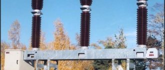
Measurement of the ground loop of the transformer transformer substation is carried out near high-voltage equipment, which can be designed for very high power, as well as voltage reaching 1-110 kV. In this regard, the threat to human life will be maximum, and it is necessary to take appropriate measures to eliminate it. In particular, it is necessary to use dielectric protective equipment - gloves, specialized tools, as well as mats placed under the feet of workers. If the measurement is performed when the equipment is turned on, then it is better to obtain the resistance indicator using special current clamps that exclude direct contact with the ground loop.
Installation nuances
Electrical installation work begins with planning. The main task is to find a rational installation option. The complex amount of work begins with drawing up a network schedule. It indicates the list of work that needs to be performed, the sequence and duration of completion, and their relationship. After approval of the network schedule, electrical equipment installers begin work.
In the case of carrying out work on the power supply of an apartment, private house, office or other objects, first of all the circuit diagram is studied. Next, all the necessary system components are purchased and delivered to the work site, the technology for installing electrical equipment, the necessary tools and control devices are selected.
In an apartment or private house, household equipment is connected taking into account its energy consumption. In addition, you must adhere to these basic rules:
- wires are laid only horizontally and vertically;
- electricity meters, switches, sockets, distribution boxes and equipment must be installed so that they are easy to maintain;
- the number of sockets must be at least 1 for every 6 m2 of room, in the kitchen - at least 3, regardless of its area;
- connections and branches of wires must be mounted in junction and branch boxes;
- A separate line is installed to power powerful electrical equipment.
TN-CS
To minimize problems with the TN-C circuit, the TN C S grounding system was introduced. This is a kind of compromise, a transitional option from the old C to the modern S.
How does it work, and what is the difference from TN-S?
In an arbitrary location, the solidly grounded neutral is combined with protective grounding. More precisely, a branch is made from the working zero. As a rule, such a point is organized at the entrance of the power cable to the facility.
On the consumer's input panel (usually this is the general input at the facility: apartment building, office building, etc.) there are already two buses: a working zero and a protective ground. Next, familiar and safe power cables go to consumers: three-wire to single-phase electrical installations, and five-wire to three-phase.
In each input panel of an apartment, or a separate room inside the facility, the protective grounding and neutral lines enter in a divided form. For the end user, the TN-CS grounding system looks like a regular and safe TN-S. In fact, the security level is far from 100%.
Why does the TN-CS system not provide complete protection against electric shock? The weak point is located in the area from the supply substation to the point where zero and protective grounding are combined. If on the way from the substation, where the solidly grounded neutral is connected to the grounding conductor, to the input switchgear at the site, the PEN line breaks, all consumers will be left without a grounding loop.
When carrying out major repairs on Soviet-built housing facilities, a grounding system must be organized. To save money, it is performed according to the TN-CS scheme. In the best case, when combining the PEN line with a newly laid protective ground bus, an electrical connection is made to the real ground loop. Most houses have a basic potential equalization system that has reliable contact with the ground. But often, to simplify their task, repair teams simply install a jumper between the new grounding bus and the working neutral, inside the input switchgear.
Advice. When concluding an agreement with the contractor for major repairs, it is necessary to discuss the issue of grounding in advance.
What if your house is connected via the TN-C system, and the next major overhaul is still many years away? Organize individual grounding in the apartment, or at least team up with neighbors in the hallway. Otherwise, the use of modern electrical appliances (boilers, electric ovens, washing machines, etc.) will become a source of increased danger.
There are unfortunate craftsmen who have a little knowledge of electrical engineering, but do not understand the responsibility for violating the PUE. Often, instead of organizing a grounding loop in accordance with GOST, a protective grounding bus is connected to metal elements of the infrastructure. At best, with cold or hot water risers, at worst, with a heating system.
Indeed, during the construction of the house, these pipes were connected to the circuit of the main potential equalization system. Initially, physical contact with the “ground” was organized. But during operation (especially if your house is several decades old), entire sections of pipelines are replaced with polypropylene. Of course, there can be no talk of any grounding in this case.
Having organized such a connection, the apartment owner is in the false confidence that his security is in complete order. Moreover, when a dangerous potential appears on the body of an electrical installation (a voltage of more than 42 volts is sufficient), all neighbors are at risk.