Device and design features
The main structural element is a semiconductor. This is a wafer of silicon or germanium crystal, which has two regions of p and n conductivity. Because of this design feature, it is called planar.
When manufacturing a semiconductor, the crystal is processed as follows: to obtain a p-type surface, it is treated with molten phosphorus, and for a p-type surface, it is treated with boron, indium or aluminum. During heat treatment, diffusion of these materials and the crystal occurs. As a result, a region with a p-n junction is formed between two surfaces with different electrical conductivities. The semiconductor obtained in this way is installed in the housing. This protects the crystal from external influences and promotes heat dissipation.
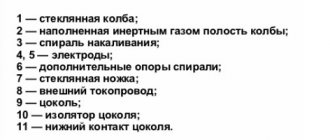
Design (1), appearance (2) and graphical display of the rectifier diode (3)
Designations:
- A – cathode output.
- B – crystal holder (welded to the body).
- C – n-type crystal.
- D – p-type crystal.
- E – wire leading to the anode terminal.
- F – insulator.
- G – body.
- H – anode output.
As already mentioned, silicon or germanium crystals are used as the basis for the p-n junction. The former are used much more often, this is due to the fact that in germanium elements the reverse currents are much higher, which significantly limits the permissible reverse voltage (it does not exceed 400 V). While for silicon semiconductors this characteristic can reach up to 1500 V.
In addition, germanium elements have a much narrower operating temperature range, it varies from -60°C to 85°C. When the upper temperature threshold is exceeded, the reverse current sharply increases, which negatively affects the efficiency of the device. For silicon semiconductors, the upper threshold is about 125°C-150°C.
Rectifiers: Features of choosing rectifier diodes
When choosing rectifier diodes, it is necessary to take into account a whole set of factors determined by: the circuit diagram of the rectifier, the frequency and magnitude of the input alternating voltage, the magnitude of the load voltage and current, operating conditions (temperature, humidity, input voltage stability, etc.), the nature of the load (capacitive , inductive), the presence of switching overloads in the load circuit, the parameters of the transformer used, etc.
First of all, it is necessary to calculate the value of the maximum reverse voltage applied to the power diodes when operating a rectifier of the selected type, and also estimate the average value of the forward current flowing through them (this can be done using the approximate formulas given in Table 3.4-1). The values obtained in this way must be adjusted depending on the nature of the load.
Tab. 3.4-1. Operating modes of diodes in various rectifiers
In the presence of an active-capacitive load (and this is most often the case), the amplitude and effective values of the power diode current can significantly exceed its calculated average value. For example, with an acceptable output ripple level of about 0.1% in a single-phase bridge rectifier with a capacitive filter, the amplitude value of the rectifier diode current can reach \( \cdot I_\) . In order to avoid overloading of diodes in terms of effective and amplitude current values and their overheating, it is necessary to tighten the requirements for the maximum forward average current (\(I_\)) of the diodes used. In practice, a coefficient of 2.2 is used for a half-wave rectifier, and 1.1 for a full-wave rectifier (i.e., the diodes used must have a value \(I_\) at least 1.1 times greater than what follows from the values obtained from the formulas from table 3.4-1).
The maximum permissible repeating reverse voltage (\(U_\)) of the diodes used is also influenced by the load (the nature of this influence can be calculated using the formulas given below). In order to avoid exceeding it at the initial moment after turning on the rectifier and during its operation (including at idle), power diodes must be selected with some margin according to this parameter.
Based on the found values of \(I_\) and \(U_\) (not forgetting also about the expected frequency of the input alternating voltage), a preliminary selection of power diodes is made using the reference data tables. The type of rectifier diodes selected is of no small importance for the characteristics of the rectifier. Let us recall that silicon, germanium or gallium arsenide diodes with a \(p\)-\(n\)-junction (including avalanche diodes), as well as silicon or gallium arsenide diodes with a junction can be used as rectifiers Schottky.
Germanium rectifier diodes were used quite widely 10..20 years ago. Currently, they are almost completely replaced by more advanced silicon and gallium arsenide devices. And only in some rather rare cases, the few positive properties of germanium diodes can determine their use in rectifiers. The main properties of germanium diodes with a \(p\)-\(n\) junction are:
- low forward voltage drop (on a germanium diode at the maximum permissible forward current, the voltage drop is approximately two times less than on a similar silicon diode), which is significant, but, unfortunately, the only advantage over silicon rectifier diodes;
- the existence of a clearly expressed saturation current when the diode is turned back on;
- significantly higher reverse current compared to similar silicon diodes;
- the breakdown voltage decreases with increasing temperature (large reverse currents of germanium diodes are the reason for the thermal nature of their breakdown), and the value of this voltage is less than the breakdown voltage of silicon diodes.
- The upper limit of the operating temperature range of germanium diodes is approximately 75 °C, which is significantly lower compared to the same parameter of silicon diodes.
Power classification
The power of the elements is determined by the maximum permissible direct current. In accordance with this characteristic, the following classification has been adopted:
- Low-current rectifier diodes, they are used in circuits with a current of no more than 0.3 A. The housing of such devices is usually made of plastic. Their distinctive features are light weight and small dimensions.
Low Power Rectifier Diodes - Devices designed for average power can operate with current in the range of 0.3-10 A. Such elements, for the most part, are made of metal housing and equipped with rigid leads. On one of them, namely on the cathode, there is a thread that allows you to securely fix the diode on the radiator used for heat removal.
Medium power rectifier diode - Power semiconductor elements, they are designed for direct current over 10 A. Such devices are produced in metal-ceramic or metal-glass housings of the pin type (A in Fig. 4) or tablet type (B).
Rice. 4. High power rectifier diodes
List of main characteristics
Below is a table describing the main parameters of rectifier diodes. These characteristics can be obtained from the datasheet (technical description of the element). As a rule, most radio amateurs turn to this information in cases where the element indicated in the diagram is not available, which requires finding a suitable analogue for it.
Table of main characteristics of rectifier diodes
Note that in most cases, if you need to find an analogue of a particular diode, the first five parameters from the table will be quite sufficient. In this case, it is advisable to take into account the operating temperature range of the element and frequency.
Rectifier diodes 1000V
| 1000 B | 1A | 30A | 1.1V | 10µA at 25°C and 50µA at 125°C | SOD123FL | |
| S3M | 1000 B | 3A | 100A | 1.2V | 5 µA at 25°C and 250 µA at 125°C | SMC |
Packaging: Blister tape on a reel with a diameter of 330 mm contains 3000 rectifier diodes in SMC. The blister tape on a reel with a diameter of 180 mm contains 3000 rectifier diodes in SOD123FL.
Principle of operation
The easiest way to explain the principle of operation of rectifier diodes is with an example. To do this, we simulate the circuit of a simple half-wave rectifier (see 1 in Fig. 6), in which power comes from an alternating current source with voltage UIN (graph 2) and goes through VD to the load R.
Rice. 6. Operating principle of a single-diode rectifier
During the positive half-cycle, the diode is in the open position and passes current through it to the load. When the turn of the negative half-cycle comes, the device is locked and no power is supplied to the load. That is, there is a kind of cutting off of the negative half-wave (in fact, this is not entirely true, since during this process there is always a reverse current, its value is determined by the Irev characteristic).
As a result, as can be seen from graph (3), at the output we receive pulses consisting of positive half-cycles, that is, direct current. This is the principle of operation of rectifying semiconductor elements.
Note that the pulse voltage at the output of such a rectifier is only suitable for powering low-noise loads, an example would be a charger for a flashlight acid battery. In practice, this scheme is used only by Chinese manufacturers in order to reduce the cost of their products as much as possible. Actually, the simplicity of the design is its only pole.
The disadvantages of a single-diode rectifier include:
- Low level of efficiency, since negative half-cycles are cut off, the efficiency of the device does not exceed 50%.
- The output voltage is approximately half that of the input.
- High noise level, which manifests itself in the form of a characteristic hum at the frequency of the supply network. Its reason is asymmetrical demagnetization of the step-down transformer (in fact, this is why for such circuits it is better to use a damping capacitor, which also has its negative sides).
Note that these disadvantages can be somewhat reduced; to do this, it is enough to make a simple filter based on a high-capacity electrolyte (1 in Fig. 7).
Rice. 7. Even a simple filter can significantly reduce ripple
The operating principle of such a filter is quite simple. The electrolyte is charged during the positive half-cycle and discharged when the negative half-cycle occurs. The capacitance must be sufficient to maintain the voltage across the load. In this case, the pulses will be somewhat smoothed out, approximately as shown in graph (2).
The above solution will improve the situation somewhat, but not much; if you power, for example, active computer speakers from such a half-wave rectifier, a characteristic background will be heard in them. To fix the problem, a more radical solution will be required, namely a diode bridge. Let's look at the operating principle of this circuit.