High voltage test
Electrical laboratory » Electrical laboratory services » Measurement methods » High voltage test method
1. General Provisions.
Electrical laboratory specialists, persons at least 18 years of age who have undergone special training and testing of knowledge of test circuits and test rules in the conditions of existing electrical installations, are allowed to carry out high-voltage tests in electrical installations.
Persons authorized to conduct tests must have a note to this effect on their certificate in the column “Certificate of the right to carry out special work” and PUE.
2. The essence of the high-voltage testing process.
Testing insulation with increased voltage makes it possible to verify the presence of the necessary insulation strength margin and the absence of local general defects that cannot be detected by other methods. Testing of insulation with increased voltage must be preceded by a thorough inspection and assessment of the condition of the insulation by other methods (measuring insulation resistance, determining the moisture content of the insulation, etc.).
The value of the test voltage for each type of equipment is determined by the established standards of the “Rules for the operation of consumer electrical installations”.
Electrical equipment and insulators of electrical installations in which they are operated are tested with increased voltage according to the standards established for the insulation class of this installation.
The insulation is considered to have passed the electrical test with increased voltage if there was no breakdown, overlap on the surface, surface discharges, an increase in the leakage current above the normalized value, or the presence of local heating from dielectric losses. If one of these factors is not met, the insulation fails to pass the electrical test.
3. Measuring insulation resistance with a megohmmeter.
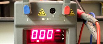
To measure insulation resistance, megohmmeters type M4100/1-5 are used for voltages from 100 to 2500V. These devices have their own power source - a direct current generator and allow direct reading of readings in megaohms.
When measuring insulation resistance relative to ground using a megohmmeter, terminal “L” (line) must be connected to the current-carrying part of the installation under test, and terminal “Z” (ground) to its body. When measuring the insulation resistance of electrical circuits not connected to ground, the megohmmeter terminals can be connected in any way.
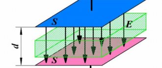
The use of clamp “E” (screen) significantly increases the measurement accuracy at high insulation resistances, eliminates the influence of surface leakage currents and thus does not distort the measurement results.
To connect a megohmmeter to the object being tested, it is necessary to have flexible wires with insulated handles and restrictive rings at the ends. The length of the wires should be as short as possible.
Before starting the measurement, it is necessary to measure the insulation resistance of the connecting wires. The value of this resistance must be no less than the upper limit of measurement of the megohmmeter.
Megaohmmeters give correct readings when the generator handle is rotated within 90-150 rpm and develop a rated voltage at 120 rpm and an open external circuit.
The insulation resistance is taken to be the 60-second value of resistance R-60, recorded on the megohmmeter scale after 60 s, and the time must be counted after reaching the normal rotation speed of the generator.
When changing the insulation resistance of objects with a large capacitance, in order to avoid vibrations of the instrument needle, it is necessary to rotate the generator handle at a frequency slightly higher than the nominal one, i.e. 130-140 rpm (increasing the speed until the arrow calms down) and take the reading only after the arrow takes a stable position.
Before starting measurements, you must make sure: that there is no voltage on the test object, that the equipment being tested, wires, cable funnels, etc. are clean, and that all parts with reduced insulation or reduced test voltage are disconnected and short-circuited.
When making measurements in damp weather, it is necessary to take into account the possible distortion of the megohmmeter readings due to wetting the surface of the insulating parts of the installation. In this case, it is necessary to use the megohmmeter clamp “E”, which must be connected in such a way as to exclude the possibility of measuring surface leakage currents.
4. Determination of insulation moisture content by absorption method.
The method is based on comparing megohmmeter readings taken after 15 and 60 seconds. after applying voltage. The method is used to determine the moisture content of hygroscopic insulation of electrical machines and transformers.
The insulation resistance is measured between each winding and the housing and between windings with isolated free windings.
The absorption coefficient is:
Cubs = R60/R15
where R60 and R15 are insulation resistances, measured respectively 60 and 15 seconds after applying voltage with a megohmmeter.
For unmoistened windings at t = 10-30°C this coefficient is 1.3-2; for humidified windings it is close to unity.
Measurements are made with a megohmmeter for a voltage of 1000-2500V.
The absorption coefficient is measured at a temperature not lower than 10°C.
5. Description of the high voltage test process.
5.1. Before starting work, the work contractor must check the serviceability of the test equipment.
5.2. When assembling the test circuit, first of all, the protective and operational grounding of the test installation is carried out, and, if necessary, the protective grounding of the housing of the equipment under test.
Before connecting the test installation to a 380/220V network, grounding is applied to the high voltage input of the installation. The cross-section of the copper wire with which the terminal is grounded must be at least 4 sq. mm.
The equipment testing circuit is assembled by the personnel of the testing team.
5.3. The test installation is connected to a 380/220V network through a switching device with a visible open circuit or through a plug located at the installation control location.
5.4. Connect the wire to a phase, pole of the equipment under test or to a cable core; it is allowed to be disconnected at the direction of the person in charge of the test, and only after they are grounded.
Before applying the test voltage to the test installation, the workman is obliged to:
- check whether all team members are in the indicated places, whether unauthorized persons are removed, whether test voltage can be supplied to the equipment;
-warn the team about the supply of voltage and, making sure that the warning is heard by all members of the team, remove the grounding from the terminal of the test installation, and then apply voltage 380/220V to it;
- from the moment the grounding is removed, the entire test installation, including the equipment under test and connecting wires, is considered to be energized and it is prohibited to make any reconnections in the test circuit and on the equipment under test;
- after completion of the tests, the work manufacturer must reduce the voltage of the test installation to 0, disconnect it from the 380/220V network, ground (or give an order to ground) the terminal of the installation and inform the team about this. Only after this can the wires be reconnected from the test installation or, if the test is completely completed, can they be disconnected and the guards removed.
6. Test procedure using the AII-70 installation.
Before each test, it is necessary to ensure that the needles of all devices are at zero, the circuit breaker is turned off, the voltage regulator handle is turned counterclockwise as far as possible, and the position of the fuses corresponds to the mains voltage. During transportation, the high-voltage transformer must be securely fastened inside the device, the voltage regulator handle is recessed, the doors are closed, the jar for testing the liquid dielectric is removed from the device, and the kenotron attachment is securely fastened.
Using a probe, you should periodically check the distance between the electrodes of the jar, which should be 2.5 mm. The probe should fit between the electrodes without moving, but not too tightly.
6.1. The procedure for testing using the UPU-1M installation.
Before each test, it is necessary to ensure that the needles of all instruments are at zero, the power switch is turned off, and the voltage regulator handle is turned counterclockwise as far as possible. This installation is intended for testing electrical protective equipment only.
SAFETY REGULATIONS
1. Before starting the tests, it is necessary to ground the apparatus, a manual spark gap (in the cases specified below), a high-voltage transformer and a kenotron set-top box with a copper wire with a cross-section of at least 4 mm2.
WORK WITHOUT GROUNDING IS NOT ALLOWED!
2. A safety fence with warning notices must be installed. It is attached from the side of the insulating tubes to the kenotron attachment (to the brackets on the casing of the microammeter), and from the side of the metal rods - to the rotating ears of the control panel frame.
3. Any switching on both the high-voltage and low-voltage sides of the device should be carried out after disconnecting the device from the network with reliable grounding of the high-voltage parts.
4. A cable or other object with a significant capacity must be grounded after testing, since a charge remains on the tested object during the test and even after, which poses a great danger to life. Do not open the door on the roof of the device without grounding the cable!
5. All high-voltage tests should be carried out wearing rubber gloves, standing on a rubber mat.
CABLE TEST
1. Ground the device and the manual arrester. If the kenotron set-top box and high-voltage transformer are located outside the device, they must also be grounded.
2. Fold back the upper rear door of the device, installing it on the bracket. Fold back the lower rear door and install the kenotron attachment on it, placing its legs under the bracket and pushing out the door.
Insert the limit switch handle into the hole in the upper door and
connect it using a key with the block limit switch
microammeter. Ground the handle.
3. Remove the spring from the spare parts and connect it with one end to the high-voltage step-up transformer, and the other to the high-voltage terminal of the kenotron attachment located in the middle of the cylinder.
Insert the plug of the kenotron console into the socket of the control panel (rear left).
Set the “Protection” handle to the “Sensitive” position.
4. Connect the test object to the kenotron attachment using a cable (screw the cable coupling onto the output of the microammeter block until it stops) and install a protective fence. The device in working position is shown in Fig. 1.
5. Plug in the power cord and, standing on the rubber mat, turn on the device.
In this case, the green signal lights up, and after pressing the machine’s “On” button. - red.
6. Smoothly rotating the voltage regulator handle clockwise, increase the voltage to the test voltage (read on the kilovoltmeter scale, calibrated in maximum kilovolts)
7. By switching the limit switching handle from a higher multiplicity to a lower one and pressing the button in the center of the handle, measure the leakage current.
Note: when measuring, multiply the microammeter reading in divisions by the limit multiple.
8.After the test, reduce the test voltage to zero and press the “Off” button.
9. Bring the rod of a manual spark gap to the discharge hook of the microammeter block and remove the capacitive charge through the discharge resistance built inside the spark gap, and then ground the microammeter block tightly by hanging the spark gap on the hook of the microammeter block or on the handle of the kenotron attachment.
Note: if necessary, the device can be turned on through a voltage stabilizer, however, due to the distortion of the voltage curve shape, use calibration data taken when working with a specific stabilizer.
The procedure for testing solid dielectrics is the same as for cables.
7. Tests with increased voltage of industrial frequency switchgear (together with switching devices).
1. Prepare the test object for testing by disconnecting voltage transformers, valve arresters, and cables from the switchgear, which must be short-circuited and grounded. Clean the equipment from dirt, dust and moisture.
2. In accordance with section 3 of this Methodology, measure the insulation resistance of the equipment being tested (with a megohmmeter for a voltage of 2.5 kV).
3. In accordance with section 5, prepare the test installation for operation.
8. In accordance with section 6 of this Methodology, test the switchgear with increased voltage; The test voltage values are given in Table No. 1. The duration of application of the test voltage is 1 min for ceramic insulation, 5 min for insulation made of solid organic materials. The duration of application of a normalized test voltage of 1 kV to the insulation of secondary circuits is 1 min.
Table No. 1
| Voltage class | Test voltage kV, insulated cells | |
| (kV) | ceramic | from TV org. materials |
| 3 | 24 | 21.6 |
| 6 | 32 | 28.8 |
| 10 | 42 | 37.8 |
8. Testing instrument transformers with increased voltage of industrial frequency.
1. Prepare the test object for testing by disconnecting the primary and secondary circuits from the transformer under test. Clean the equipment from dirt, dust and moisture.
2. In accordance with section 3 of this Methodology, measure the insulation resistance of the equipment being tested (with a megohmmeter for a voltage of 2.5 kV).
3. In accordance with section 5, prepare the test installation for operation.
4. In accordance with section 6 of this Methodology, test the primary winding of the instrument transformer with increased voltage at industrial frequency; The test voltage values are given in Table No. 2. Duration of application of the test voltage: for voltage transformers 1 min; for current transformers with ceramic, liquid or paper-oil insulation 1 min; for current transformers with insulation made of solid organic materials or cable masses 5 min. The duration of application of a normalized test voltage of 1 kV to the insulation of the secondary windings along with the circuits connected to them is 1 minute.
Table No. 2
| Instrument transformer insulation design | Test voltage kV, at rated voltage kV | ||
| 3 | 6 | 10 | |
| Normal | 21,6 | 28,8 | 37,8 |
| Weakened | 9 | 14 | 22 |
9. Testing of power cables with a rated voltage above 1 kV with increased rectified voltage.
1. In accordance with section 3, measure the insulation resistance with a megohmmeter for a voltage of 2.5 kV. For power cables with voltages above 1 kV, insulation resistance is not standardized. Repeat the insulation measurement after testing the cable with increased rectified voltage.
2. In accordance with section 6, test the power cable with increased rectified current voltage. Test voltage values and
The duration of application of the test voltage is given in Table No. 3. During the test with an increased voltage of the rectified current, attention is paid to the nature of the change in the leakage current. The cable is considered to have passed the test if no breakdown occurred, there were no sliding discharges or surges of the leakage current or its increase after it reached a steady value.
10. Registration of test results.
The test results according to this Methodology are documented in standard protocols.
Rectified current test voltage for power cables.
Table No. 3
| Cable insulation and grade | Test voltage for kV cables | Test duration (min) | ||
| 3 | 6 | 10 | ||
| Paper | 18 | 36 | 60 | 10 |
| Rubber | 6 | 12 | 5 | |
| Plastic | 15 | 10 |
How is insulation resistance measured using special equipment?
When using a device for high-voltage testing - a megger, which has its own separate power source, namely a DC generator, the insulation resistance is measured. This device can operate on voltage from 110 to 2000V.
When using it to measure insulation resistance with respect to ground, one clamp must be connected to the conductive part of the megger, and the other to its body. And if the electrical circuits are not connected to the ground surface, then the connection of the terminals may be different.
When measuring, it is possible to use a special clamp, which is responsible for the accuracy of the indicators, since it is not affected by leakage of surface currents. To measure with a megger, you need flexible wires that connect it to the objects being tested and have limiters at the ends. Such wires can be used for ignition systems in tractors or similar ones. Before testing begins, these wires must be checked for current transmission to ensure that the readings are correct. It must be taken into account that in wet weather the megger readings are distorted.
TEST STANDARDS
The test set voltage should be selected according to the highest voltage accepted for the cable insulation being tested. According to the PUE, the test voltage values and test duration must be no less than those given in table. 1.
Table 1 test voltage values and duration of cable tests
| Cable name | Rated cable voltage, kV | Test voltage, kV | Test duration, min |
| Paper insulated | 3—10 | 6 Uv | 10 |
| 20—35 | 5 UB | 10 | |
| 110 | 300 | 15 | |
| 220 | 450 | 15 | |
| Rubber insulated | 3 | 6 | 15 |
| 6 | 12 | 5 |
The given test voltage values in the table are given on the rectified voltage side; therefore, the effective voltage value of the test setup on the AC side will be several times lower.
b) Basic method
According to GOST 17512-72 [L. 9-2] the main method for measuring the amplitude value of high voltage is the ball gap method. Measurement of high voltage industrial frequency when testing transformers is carried out with a low voltage voltmeter of class 0.5, calibrated with a ball gap. The arrester is connected to the HV side and the voltmeter is connected to the LV side of the test transformer directly or through a VT. According to the standard, the voltmeter is calibrated, as a rule, when the test object is turned on and the voltage is less than 80% of the test voltage. This requirement is caused by a change in the transformation ratio of the test transformer when it is
capacitive current loading of the test object, as well as possible distortion of the generator voltage waveform, which usually cause an increase in voltage on the secondary side of the test transformer. Voltage increase with capacitive load: (9-6) where Un.n is the rated secondary voltage of the test transformer; IR - short-circuit voltage, %; Iс is the capacitive load current on the secondary side; In is the rated current of the secondary winding of the test transformer.
The transformation ratio of a test transformer loaded with capacitive current is equal to:
or the coefficient of increase in the test voltage from the capacitive load, where k0 is the transformation ratio at XX; Uin is the rated HV voltage of the test transformer; Utest - test voltage.
For example, with the capacitance of the LV+KO windings of a transformer type AODTSTN-417000/750 relative to the housing and other windings C = 101,000 pF (Table 8-7), the charging current when testing these windings with an applied voltage of 35 kV according to (9-1) Ic = 314 · 101 000 · 35 · 10-9 = 1.1 A. When testing the indicated windings from a test transformer of the IOM-300 type when connecting the secondary winding at 150 kV and the short-circuit voltage of the test transformer u = 10.2% (Table 9- 7) test voltage increase factor according to (9-8): kt/k0= 1/(1—150-1.1 10.2/35-1 100) =1.89.
Thus, if the test voltage is measured on the LV side of the test transformer without calibration using a ball gap or according to calibration data when testing a transformer of another type, for example with a lower winding capacitance or with a higher test voltage (for example, 85 kV), then the LV windings + KO the transformer specified in the example will be tested at a voltage higher than the normalized voltage by more than 1.5 times.
When measuring industrial frequency voltage, a ball spark gap produces at least three consecutive discharges with an interval of at least 1 min. The arithmetic average of the values obtained (using a voltmeter) is considered to correspond to the discharge voltage at which the ball gap is installed. The discharge voltage values should not differ from the average by more than +3%. The ball gap method is based on that. that the breakdown voltage of the air gap between two spherical electrodes of the spark gap, designed in accordance with the requirements of GOST 17512-72, subject to certain conditions, depends on the amplitude value of the voltage, the diameter of the balls and the relative density of the air. GOST 17512-72 specifies the discharge voltages of ball arresters with a ball diameter of 2-200 cm for alternating sinusoidal voltages under normal atmospheric conditions of 20 ° C and 101,300 Pa (1013 mbar corresponds to 760 mm Hg at 0 ° C). Under these conditions, the relative air density δ is taken equal to 1. For other atmospheric conditions, the values of discharge voltages taken from Table. 1 of Appendix 1 of GOST 17512-72, are determined by dividing (the amplitude value) by V2 and multiplying by the correction factor k. The kp coefficient is a function of the relative air density, determined by the formula:
where P is atmospheric pressure, Pa; t—ambient air temperature, °C. If the pressure is expressed in mmHg. Art. at 0°C, then the formula looks like: (9-10) The values of the correction factor depending on the relative air density δ are given in table. 9-3.
Correction factor CP Table 9-4 Resistances of the protective resistor
When measuring industrial frequency voltage with a ball spark gap, a non-inductive protective resistor is included in the measuring circuit in series with the spark gap, the resistance of which at a frequency of the measured voltage of 50 Hz should not exceed the values indicated in the table. 9-4. At a frequency other than 50 Hz, the maximum value of the resistor changes in direct proportion to the 50/f ratio.