High-voltage cable lines (CL) are exposed to weight and soil shifts, temperature changes and other external factors. Testing cable lines with high voltage allows you to check the condition of the insulating layer and promptly replace damaged areas. Regularly conducting such checks is a necessary condition for the trouble-free operation of cable lines and helps prevent accidents, property damage and other unpleasant consequences.
Testing of 10 kV high voltage cable is required:
- after laying or replacing the cable - before filling the trench and turning on the power line;
- in relation to used cable lines - after a long outage and scheduled or unscheduled repairs;
- in relation to the cable sheath, which is laid in the ground and operates without electrical breakdowns - with a frequency of 5 years;
- for main cable lines - with an interval of 3 years;
- for reserves - with a 5-year frequency;
- for main and reserve cable lines supplying facilities of special importance - annually.
When carrying out excavation work, landslides, sedimentation or erosion of soil, extraordinary tests of cable lines are required. Additional checks are carried out upon completion of work.
Engineering has all the necessary licenses for testing high-voltage cables, a well-coordinated team of professionals and certificates that give the right to carry out all the necessary tests and measurements. By choosing the ProfEnergia electrical laboratory, you are choosing reliable and high-quality operation of your equipment!
If you want to order high-voltage tests, as well as for other questions, call: +7 (495) 181-50-34.
Test conditions
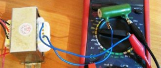
High voltage testing of power cables must be carried out by competent personnel who are at least 18 years of age and have undergone appropriate training. First, the CLs are inspected to identify defects in the insulating layer. Significant contamination is removed from the surface. The funnels are wiped clean.
The permissible air temperature for testing work is from 0 °C. First of all, the resistance of the cable insulation coating is measured with a megger. The required high voltage resistance is not lower than 1 MOhm. Such measurements make it possible to detect significant defects, violations of integrity and errors made during repair activities.
Insulation resistance is measured as follows:
1. Using an increased voltage device, check whether the cable is de-energized.
2. Grounding with clamps is installed on the cable cores.
3. On the opposite side, the cable outlets are left free. Warnings are placed here or a supervisory person is left to avoid accidental passers-by becoming energized.
4. Insulation resistance is measured with a megger, 60 seconds per wire.
5. The obtained measurement results are recorded in a notepad.
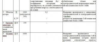
| Item no. | names | brand | basic error threshold |
| 1 | Megaohmmeter | ESO 202/2-G | ±15% |
| 2 | High voltage apparatus | AID-70 | ±4% |
| 3 | Voltage indicator with phasing tube | UVN-80-2M | — |
Scope of acceptance tests.
In accordance with the requirements of the PUE, the scope of acceptance tests of power cable lines includes the following work.
- Checking the integrity and phasing of cable cores.
- Insulation resistance measurement.
- Test with increased voltage of rectified current.
- Power frequency high voltage test.
- Determination of active resistance of cores.
- Determination of the electrical working capacitance of the cores.
- Measurement of current distribution in single-core cables.
- Checking protection against stray currents.
- Test for the presence of undissolved air (impregnation test).
- Testing of feeding units and automatic heating of end couplings.
- Monitoring the condition of the anti-corrosion coating.
- Checking oil characteristics.
- Ground resistance measurement.
Power cable lines with voltage up to 1 kV are tested according to paragraphs 1, 2, 7, 13.
Power cable lines with voltages above 1 kV and up to 35 kV - according to clauses 1-3, 6, 7, 11, 13, and with voltages of 110 kV and above - in full, provided for by these instructions.
High voltage cable testing
Testing a 10 kV cable with increased voltage makes it possible to detect problems not detected by a megger and bring it to breakdown in faulty places. The increased voltage is supplied through a high-voltage wire of special equipment to 1 core, and portable grounding is applied to the rest. The voltage increases smoothly to a maximum of 60 kW.
The required test time (5-10 minutes) is then counted, and current and voltage leakage are carefully monitored. At the final minute, the current leakage is counted according to the readings of the microammeter. The voltage gradually decreases to zero. The high-voltage terminal of the equipment is grounded. All conductors are checked in the same way. The results of the checks are entered into a notebook. The permissible difference in current leakage between phases is not higher than 50%.
The cable is considered to have passed the test in the absence of:
- current surges, breakdowns;
- reducing the resistance of the insulating layer;
- increase in current leakage;
- surface discharges.
If the leakage current increases, the cable line is allowed to operate provided that it is monitored and tested more often. When a breakdown is detected, work is suspended and a search for faulty areas begins.
| SCL, kV | voltage, kV | DTU, mA | DKA |
| 6 | 36 | 0,2 | 8 |
| 10 | 45 | 0,3 | |
| 50 | 0,5 | ||
| 60 |
T. Permissible leakage currents and asymmetry coefficients for SCL.
Test with increased voltage of rectified current.
Power cables with voltages above 1 kV are tested with increased rectified current voltage.
The magnitudes of the test voltages and the duration of application of the normalized test voltage are given in Table 5.
Table 5. Rectified current test voltages for power cables
| Cable type | Test voltages, kV; for cables for operating voltage, kV | Test duration, min | |||||||
| 2 | 3 | 6 | 10 | 10 | 35 | 110 | 220 | ||
| Paper | 12 | 18 | 36 | 60 | 100 | 175 | 300 | 450 | 10 |
| Rubber brands GTSh, KSHE, KSHVG, KSHVGL, KSHBGD | — | 6 | 12 | — | — | — | — | — | 5 |
| Plastic | — | 15 | — | — | — | — | — | — | 10 |
The test methodology for high-voltage rectified current, as well as installations and equipment for testing, are presented in high-voltage insulation tests of electrical equipment.
During testing, the voltage must gradually rise to the test value and be maintained constant throughout the test period. The test voltage for cable lines with voltages up to 10 kV is raised within 1 minute, and for cable lines with voltages of 20-35 kV - at a speed of no more than 0.5 kV/s.
If the test voltage is monitored using a voltmeter connected on the primary side of the step-up transformer, then some error may be introduced into the measurement results due to the voltage drop in the elements of the test circuit, in particular in kenotrons.
Measurement of leakage currents of a 3-10 kV cable when testing with suspended rectified voltage is carried out using microammeters connected either to the high voltage side of the testing installation or to the zero of the test transformer. When using the latter scheme for measuring leakage currents, the reading may be distorted due to parasitic leakage currents.
When testing power cable lines with increased rectified voltage, their condition is assessed not only by the absolute value of the leakage current, but also by taking into account the nature of the change in the leakage current over time, the asymmetry of the leakage currents by phase, the nature of charge retention and decay, etc. In operation, it is accepted that a cable line can be put into operation if the leakage currents have a stable value, but do not exceed 300 μA for lines with a rated voltage of up to 10 kV. For short cable lines (up to 100 m long) without couplings, permissible leakage currents should not exceed 2-3 µA per 1 kV test voltage. The asymmetry of leakage currents by phase should not exceed 8-10, provided that the absolute values of the currents do not exceed permissible values.
For proper insulation of a power cable, the leakage current decreases depending on the duration of application of the test voltage, and the higher the quality of the insulation, the greater. For a power cable with defective insulation, the leakage current increases over time. If there is a noticeable increase in the leakage current when testing a power cable, the test duration increases to 10-20 minutes. If the leakage continues to increase, if it is not caused by defects in the terminations, the test should be carried out until the cable insulation breaks down.
During testing, the voltage from the rectified installation is applied to one of the cores of the cable under test. The remaining cores of the cable being tested, as well as all cores of other parallel cables of this connection, must be reliably connected to each other and grounded. For three-core cables, the insulation of each core relative to the sheath and other grounded cores is tested. For single-phase cables and cables with separately leaded conductors, the insulation of the conductor relative to the metal sheath is tested.
The cable is considered to have passed the test if no breakdown occurred, there were no sliding discharges or impulses of the leakage current or its increase after it reached a steady value.
After each test of the cable line circuit, it must be discharged according to the given method.
Checking the integrity of the cores
The integrity of the cores is checked with an ohmmeter. A closed circuit is formed with the core and conductor, and the resistance of the cable components is measured sequentially. Before using the ohmmeter, inspect it for damage. Then its trial testing is carried out with the probes separated and connected.
When checking with a mechanical device, to eliminate errors, it is placed on a horizontal plane. Due to the variability of the resistance of the insulating layer depending on external factors, the test takes at least 1 minute. The values are recorded from 15 seconds.
Checking the integrity of the cores includes the following steps:
- Removal of people from the tested part of the electrical installation.
- Grounding the terminals of the test object.
- Lack of voltage control.
- Removing and cleaning the cable insulation coating.
- Installation of measuring tentacles of a megohmmeter.
- Removing grounding.
- Check the insulation of all cores one by one.
- Recording the test results in the protocol.
- Disabling the machines and disconnecting the neutral wires from the terminal.
All inspection work is carried out wearing rubber gloves, with strict adherence to safety requirements. If a defect is detected, the part being tested is disassembled in order to find and eliminate the fault. Upon completion of the work, the residual charge of the megohmmeter is removed by a short circuit, discharging the probes with each other.
Testing of XLPE insulated cable
Cable with XLPE insulation is tested with alternating current voltage. By changing the polarity of the charge, it is possible to compensate and discharge the accumulated charges. When testing with a particularly low frequency voltage, it is possible to obtain the maximum rate of breakdown development and detect problems. To prevent damage to the cable line, the supplied voltage must have the form of a strictly symmetrical sinusoid.
Tests of cable lines, high-voltage tests of cross-linked polyethylene cables and inserts with XLPE insulation are mandatory before putting lines into operation and after completion of repair activities. Testing of a cable made of cross-linked polyethylene 10 kV and other voltages is carried out according to the instructions UP-B-1. Its requirements are presented in the table
Power frequency high voltage test.
Testing with increased power frequency voltage is allowed
produce for 110-220 kV lines instead of testing with increased voltage of rectified current.
The values of the test voltage of industrial frequency are given in table. 6.
Table 6. Power frequency test voltage values
| Cable operating voltage, kV | Test voltage kV | Test voltage relative to ground, kV | Test duration, min |
| 110 | 220 | 130 | 5 |
| 220 | 500 | 288 | 5 |
Test methods and installations for testing insulation with increased voltage of industrial frequency are given for testing insulation of electrical equipment with increased voltage.
Testing the sheath of XLPE cable
The sheath of XLPE-insulated cables is often damaged due to mechanical or corrosive influences. If this defect is not corrected in a timely manner, the main insulation will lose its protective qualities and a breakdown will occur. The sheath of an XLPE cable with a voltage of 10–20 kV is tested with a voltage of 5 V DC for 10 minutes. When a breakdown is detected, a local search for the location of the defect is carried out.
Sheaths of 10–20 kV cables with XLPE insulation must be tested:
- before putting the cable line into operation;
- 2.5 years after the cable line was put into operation and thereafter with an interval of 5 years;
- after repair of the insulating layer;
- during excavations carried out in the security area of the cable line - due to the risk of damage to the protective shells.
For comprehensive testing of cables, testing of 10 kV power cables and their sheaths, a special hardware complex is used. It identifies damaged areas and pinpoints the location of defects with high precision automatically using a step-by-step voltage method.
| type of power cable, kV | less than 1* | 6 | 10 | ||
| paper insulating sheath | |||||
| P | 6 | 36 | 60 | ||
| TO | 2,5 | ||||
| M | — | ||||
| plastic insulating shell | |||||
| P | 3,5 | 36 | 60 | ||
| TO | — | ||||
| M | — | ||||
| rubber insulating shell | |||||
| P | 6 | 12 | 20 | ||
| TO | |||||
| M | 6* | 12* | 20* | ||
Test with increased voltage of rectified current.
Testing the insulation of cable lines with increased voltage of rectified current is carried out in order to identify local concentrated defects that are not detected when measured with a megohmmeter, by bringing them to breakdown during the test. Such a test with increased voltage of rectified current is carried out from a special installation such as: AID-70, SKAT-70, etc.
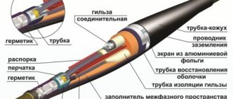
The voltage from the installation is applied in turn to each phase of the cable, while grounding the other two phases and the cable sheath (similar to measuring insulation with a megohmmeter). The circuit for testing the cable with increased voltage of rectified current is shown in Figure No. 3.
Rice. No. 3 Testing the cable with increased rectified voltage.
Insulation of single-core cables without metal screen (sheath, armor),
laid in air are not tested. The insulation of single-core cables with a metal screen (sheath, armor) is tested between the core and the screen. The insulation of multi-core cables without a metal screen (sheath, armor) is tested between each core and the remaining cores connected to each other and the ground.
The insulation of multi-core cables with a common metal screen (sheath, armor) is tested between each core and the remaining cores connected to each other and the screen (sheath, armor). For all of the above types of tests, metal screens (shells, armor) must be grounded. Plastic sheaths (hoses) of cables laid in the ground are tested between screens (sheaths) disconnected from the ground and the ground. Plastic sheaths (hoses) of cables laid in air are not tested. The test voltage value is taken in accordance with table No. 2
Test voltage kV, for power cables.
Table No. 2
| Type of test | Test voltage (kV) for cable lines | ||
| Paper insulated cables | |||
| Up to 1kV | 6kV | 10kV | |
| P | 6 | 36 | 60 |
| TO | 2,5 | 36 | 60 |
| M | — | 36 | 60 |
| Type of test | Plastic insulated cables | ||
| Up to 1kV* | 6kV | 10kV | |
| P | 3,5 | 36 | 60 |
| TO | — | 36 | 60 |
| M | — | 36 | 60 |
| Type of test | Rubber insulated cables | ||
| Up to 3kV | 6kV | 10kV | |
| P | 6 | 12 | 20 |
| TO | 6 | 12 | 20 |
| M | 6** | 12** | 20** |
* - high voltage testing of single-core cables with plastic insulation without armor (screens) laid in the air is not carried out.
** - after repairs not related to cable reinstallation, the insulation is checked with a megohmmeter for a voltage of 2500V, and testing with increased rectified voltage is not performed.
For cables for voltages up to 10 kV with paper and plastic insulation, the duration of application of the full test voltage during acceptance tests is 10 minutes, in operation 5 minutes. For cables with rubber insulation for voltage 6-10 kV, the duration of application of the full test voltage is 5 minutes.
Permissible leakage currents depending on the test voltage and permissible values of the asymmetry coefficient when measuring leakage current are given in Table No. 3. The absolute value of the leakage current is not a rejection indicator. Cable lines with satisfactory insulation must have stable leakage current values. During testing, the leakage current should decrease. If there is no decrease in the leakage current, or if it increases or becomes unstable, the test is carried out until the defect is identified, but not more than 15 minutes.
Prices for electrical measuring work "PROFENERGIYA":
| Services | Unit | Cost per unit of measurement, rub. | |
| Electrical installations over 1000 V to 35 kV | |||
| Checking compliance of the installed electrical installation with the requirements of the design documentation | inspection | From 3000 | |
| Checking the presence of a circuit between grounding conductors and grounded elements | dot | From 25 | |
| Testing of fuses, fuse-disconnectors for voltages over 1 kV. | PC. | From 490 | |
| Testing of power cable lines with voltage up to 20 kV. | PC. | From 9500 | |
| Testing of power cable lines with cross-linked polyethylene insulation with voltage up to 35 kV. | Trial | From 8000 | |
| Testing of power transformers, autotransformers, oil reactors and grounding arc arresters with rated voltage up to 35 kV. power up to 63000 kVA | PC. | From 15000 | |
| Testing of switchgear and switchgear. | PC. | From 14900 | |
| Testing of oil, air, vacuum circuit breakers, disconnectors, short circuiters and separators. | PC. | From 1400 | |
| Testing of complete busbars (busbars). | PC. | From 2500 | |
| Testing of busbars and connecting busbars. | PC. | From 2500 | |
| Testing of valve, tubular arresters and surge suppressors. | PC. | From 4000 | |
| Testing of bushings and bushings. | PC. | From 5000 | |
| Testing of suspension and support insulators | PC. | From 6000 | |
| Testing of dry current-limiting reactors. trial | Trial | From 5000 | |
| Inspection of cells (checking and adjusting relay equipment) | Complex | From 15000 | |
| Testing of AC electric motors with rated voltage up to 20 kV. | Complex | From 20000 | |
| Checking switchgear and their connections | Complex | From 10000 | |
| Testing of electrical equipment with increased voltage 1 kV industrial frequency | Measurement | From 500 | |
| Testing of synchronous generators and compensators | Measurement | From 8000 | |
| Testing of measuring current transformers | Trial | From 5000 | |
| Testing of voltage transformers | Trial | From 3500 | |
| Testing of dry current-limiting reactors. | Trial | From 4500 | |
| Capacitor testing. | PC. | From 1800 | |
| Transformer oil testing | Sample (1 liter) | From 8000 | |
| Testing power lines with voltages above 1 kV | Complex | From 20000 | |
| Comprehensive testing | |||
| Carrying out electrical measuring work with the preparation of a technical report from 1000V to 35kV | |||
| Acceptance tests. | Complex of works | From 20000 | |
| Performance tests. | Complex of works | From 20000 | |
| For certification purposes | Complex of works | From 8000 | |
| Engineer visit | Departure | For free | |
| Drawing up single-line diagrams | PC. | From 2000 | |
| Drawing up a grounding device passport | PC. | From 10000 | |
Locations of insulation defects are also determined in stage 2. First, preliminary localization is carried out using the loop method and precision bridge, and then precise identification of defective locations is carried out using the step voltage technique.
To identify locations of damage to the cores themselves, various technologies are used:
- for a 3-core cable – burning;
- for initial localization - non-burning methods;
- for high-precision detection of defects - acoustic method.
Timely testing of high-voltage lines is necessary to increase the reliability of electrical networks and increase the period of their uninterrupted use.
| Carrying out electrical measuring work with the preparation of a technical report from 1000V to 35kV | |||
| Acceptance tests. | Complex of works | From 20000 | |
| Performance tests. | Complex of works | From 20000 | |
| For certification purposes | Complex of works | From 8000 | |
| Engineer visit | Departure | For free | |
| Drawing up single-line diagrams | PC. | From 2000 | |
| Drawing up a grounding device passport | PC. | From 10000 | |
Modern electrical capabilities make it possible to provide energy to any national economic facility. Due to the density of urban infrastructure, as well as the minimum distance between industrial and manufacturing enterprises, power lines are equipped with high voltage power cables. When distributed to consumption points, it is transformed to the required level.
Testing of cable lines, high voltage, methods, goals
During the installation or operation of cable lines, various types of damage sometimes occur, the main of which are:
— break of one of the wires;
- short circuit between cores or to ground due to aging of insulation, due to corrosion of metal shells, etc.;
— oil leaks as a result of breaks in oil-filled cables;
- mechanical impacts - these damages relate to lines laid in the ground, etc.
Also, during operation, “weaknesses” may arise in the insulation of cable lines; due to errors associated with the human factor, defects in sealing, installation of connecting or end couplings may be observed.
In order to preliminarily identify and eliminate any of the above damage to the cables, tests are carried out. The methodology for conducting them is regulated by regulatory and technical documents, SNiP, PUE, PTEEP, etc. The phased sequence of testing cable lines is set out in the PUE (Chapter 1.8, clause 1.8.40), PTEEP (Appendix 3, clause 6). Their main task is to bring defective or weak points to breakdown, which thereby contributes to premature emergency failure of the cable.
Those newly introduced into work must be tested after cap. repairs, as well as periodically during work, all cable lines. It is recommended to carry out tests in favorable weather conditions.
Imported cable and wire products must be tested in accordance with the manufacturer's instructions and instructions.
The measurement results must be compared with data obtained during previous tests, including the initial tests carried out at the manufacturer.
The test results are documented in the form of a “Protocol”, the form established by the regulations.
Scope of testing cable lines from 1000 V and more than 1000 V
Power cables with rated voltage up to 1000 V are tested in accordance with sections: 1, 2, 4.
Power cables with a rated voltage of more than 1000 V are tested in accordance with sections: 1, 2, 3, 4.
Section 1 – Checking for integrity and correct phasing of cable cores
Section 2 - Insulation Resistance Measurements
Insulation resistance measurements are carried out with a special device - a megger. The exposure must be carried out for a minute with a voltage of 2.5 kV. The insulation resistance of cable products up to 1 kV must be 0.5 mOhm or more.
There is no regulated resistance value for a cable line with a voltage of more than 1 kV, but the recommended value is 10 MOhm.
Section 3 - High Voltage Test
The next stage is testing with increased voltage of rectified current. Any power lines with an operating voltage above 1 kV must undergo this test. These tests for cable lines with a rated voltage of more than 1 kV are carried out within the time limits established by the order established by the table of scheduled maintenance, but not less than once every 3 years. After commissioning or major repairs, the cables are subjected to tests with an operating voltage of up to 10 kV at Unom, and during preventive tests - (5-6) Unom. The test duration for the phase is 10 minutes.
The result of the test is satisfactory if no breakdowns occur during the test, sliding discharges, leakage current shocks or an increase in its steady-state value are not observed, and the insulation resistance does not change sharply.
Section 4 - Measurements of current distribution of single-core cables
The uneven distribution of currents along cable lines should not be more than 10%, since such operating modes can lead to overloads and failure of the cores.
Why are tests carried out?
During long-term operation, cable lines are inevitably exposed to external influences.
The factors that determine the wear of the CL include:
- sharp amplitude of seasonal temperatures;
- groundwater activity;
- excessive atmospheric activity (ice storm is especially dangerous);
- soil mobility.
In addition, constant overloading of lines has a detrimental effect. As the insulating layer wears out, the CL gradually loses its original performance characteristics.
To prevent external factors from having a destructive effect, it is recommended to systematically test cable lines with high voltage. Proper organization of testing ensures the flawless functioning of networks, as well as minimizing emergency and abnormal situations.
Who has the right to perform an inspection?
Since this type of work is a task of increased complexity and contains a potential danger to health and even life, employees with permits are allowed to test cables.
For example, when working with a megohmmeter, electrical safety group III is required, and for performers of a full range of work - IV. The organizer (leader) is required to have group V in electrical safety. The fact of admission is recorded in the appropriate certificate. In addition to the group, it reflects information about aptitude tests.
In this case, the minimum work experience in the profile is 3 full months. This refers to direct experience in testing cables that took place during the specified 3 months. Without the practice of high-voltage testing, even an actual three-month presence in the profession is considered insignificant.
Tests: how they are carried out
The first check for serviceability is carried out immediately after laying the cable, even before the official commissioning. Later in everyday functionality this operation is repeated.
Work is not carried out at sub-zero temperatures. Even a slight drop in the mercury column beyond zero is a good reason to cancel tests. The fact is that icy water particles have dielectric properties (some of them are very likely to get into the cable). High voltage tests will be useless or the results obtained will not be reliable.
The test method with increased rectified voltage is that it is applied to each cable core (while the rest are grounded).
Leakage is defined as follows:
- insulation test to earth;
- phase-to-phase insulation testing.
The performance of the CL is recognized if shocks and small discharges are not traced. When completed, the line is discharged.
High-voltage testing of cross-linked polyethylene cable (regulations)
| Periodicity |
Important ! If there are no breakdowns, the cable sheath is inspected for integrity once every 5 years. | |
| First method | Second method | |
| Testing 10 kV XLPE cable | It is carried out using alternating voltage with a frequency of 0.1 Hz. Duration: 30 minutes. If the cable line repair work has just finished, 20 minutes is enough. Important ! An industrial diagnostic VLF installation for XLPE cables is used. Test procedure:
| Checking CL 10 6 kV is performed with alternating voltage (10 or 6 kV, respectively). Voltage is applied between the core and the screen. Duration - 24 hours. Test procedure:
Important ! Timing begins from the moment the voltage rises to the maximum level. |
| Current leaks considered normal | For a 6 kV cable - up to 200 µA. For 10 kV - no more than 500 µA. | |
A licensed engineer conducts 10 kV cable testing with quality assurance. Availability of licenses from Rostekhnadzor and SRO, modern equipment - a guarantee of the accuracy of the results obtained. Based on the test results, our specialists prepare a report.
High rectified voltage test:
a) cables with voltages above 1000 V (except for rubber cables 3-10 kV)
Performed during major and current repairs. Group cables at substations can be tested without being disconnected from the busbars. It is recommended to test the rectified current of cables located within the same switchgear or building with increased voltage no more than once a year.
The values of rectified current test voltages are presented in table. 13.
The procedure for conducting tests with increased voltage of rectified current should be guided by the instructions above.
Table 13. Rectified current test voltage
| Lines with operating voltage, kV | Type of tests and test voltage, kV | Test duration of each phase, min | |
| TO | T,M | ||
| 2-10 | 6 Unom | (5÷6) Unom | 5 |
| 20-35 | 5 Unom | (4÷5) Unom | 5 |
| 110 | 250 | 250 | 15 |
| 220 | 400 | 400 | 15 |
b) 3-10 kV cables with rubber insulation (for example, brands KShVG, EVT) Produced at K test voltage 2·Un for 5 minutes.