Electric drill - remember the design of the tool
An electric drill is a type of tool that is designed for drilling different types of materials, including concrete and reinforced concrete. Only for this you will need to use a tool with an impact drilling function or an impact drill. You can find out how the tool works if you take it apart. A brief description of the design of Soviet and foreign-made electric drills is described below.
It should be noted that the design of modern drills of domestic and foreign production differs from the design of Soviet tools. Only these are minor differences, which consist in the absence of reverse on an electric drill, as well as impact drilling. So, structurally, an electric drill consists of two main parts - electrical and mechanical. The mechanical part is based on the following structural elements:
- Gearbox - a set of gears, due to which the speed decreases and the torque from the electric motor shaft increases
- The cartridge is an executive body that is designed to secure working attachments
- Bearings are supporting mechanisms for shafts and axles that ensure their rotation.
- Impact mechanism - in electric impact drills this device is part of the gearbox
The electrical component of any corded electric drill consists of the following elements:
- A commutator type motor consisting of a stator (fixed part), rotor or armature (moving part) and a collector (copper plates or lamellas through which current is supplied to the armature winding)
- Graphite or carbon brushes are a transmission device through which current is transmitted to the rotor winding. Brushes are consumables, and when they spark, this indicates their wear.
- Start button - depending on the model of the electric drill, the switches can be regular or with a built-in speed controller
- Reverse button - Soviet drills do not have such devices. This is a polarity reversal mechanism through which the direction of rotation of the tool chuck changes. Installed separately or integrated into the start button
- A ferrite ring is an element (filter) through which noise in the network is smoothed out
- A capacitor is a filter element that prevents interference from entering the network
- Power cord - the link between the electrical outlet and the tool
The photo above shows the design of the drill with the main components. Sooner or later, it becomes necessary to repair the drill due to the failure of its individual components and mechanisms. To do this, you first need to inspect the tool, identify the cause of the malfunction, and eliminate it. More details about what types of drill breakdowns there are, how to identify and fix them, are described in the material.
This is interesting!
Old Soviet drills do not have a reverse mechanism or an electronic speed controller. Instead of an electronic regulator, a mechanical one is used, consisting of gears of different diameters and numbers of teeth. This method of adjustment is more reliable, since reducing the speed does not affect the power. However, this method of speed control is expensive, as it requires the additional use of a pair of gears. If one pair of gears wears out, you can continue to use the tool. Below are photos showing the design of the mechanical speed controller of an old Soviet drill.
Tool design
Drills may be different, but the design of all types is approximately the same, since the operating mechanism of the tools is the same.
To understand how a tool should be repaired, you need to know its structure. Minimal knowledge about the design of the drill will make it easier to determine the breakdown that caused interruptions in operation.
In addition, knowing how the tool works and having an idea of what parts are included in the drill makes it easier to replace faulty parts.
From the outside, the drill is visually divided into two parts: the drill, which is inserted into the chuck, and the body, inside of which there is a mechanism that ensures the direct operation of the drill, that is, the rotation of the drill. The mechanism of the tool is divided into an electrical part and a mechanical part.
1-ventilation grille; 2-power regulator for tightening screws/screws; 3-power regulator/torque limiter; 4-impact switch; 5-keyless chuck; 6-self-centering cams; 7-cartridge fastening; 8-reducer; 9-cooling fan impeller; 10-electric motor; 11-reverse lever; 12-trigger; 13-power cord clamp; 14-terminal power cord
The electric motor is the main part of the electrical component of the tool mechanism.
In addition to the motor, it includes a mains cable or battery (the presence of one or the other depends on whether the drill is powered by mains or batteries), start, reverse and speed control buttons, a capacitor, and a brush holder mechanism that includes contact brushes.
The two-phase electric motor of the tool consists of a rotor with a commutator and a stator.
If the drill is a hammer drill, then the mechanical design is more complicated. Gears, a ram and a striker as part of the mechanical part change the principle of operation of the drill and make it an impact drill.
Each problem that arises while working with a drill indicates a specific malfunction; you just need to know what kind of breakdown of the mechanism manifests itself in one way or another. Based on such unique symptoms, you can quickly determine what exactly is wrong with the instrument.
What you need to diagnose electric drill breakdowns
Where should you start troubleshooting an electric drill? Of course, from the first signs, by which it becomes clear where the breakdown is hidden and which part needs repair. It is easy to identify mechanical problems with a drill, but with the electrical part everything is much more complicated. Here you will need appropriate tools from which you can draw conclusions about the malfunction of certain components, parts and mechanisms of the tool. To identify breakdowns in the electrical part of the electric drill, you will need to prepare the following tools:
- Voltmeter or multimeter. Preference should be given to the second option, as it is more effective and multifunctional
- Device for measuring interturn short circuit in an armature
To diagnose the mechanical part, you will need to perform the following manipulations:
- See what specific function the drill does not perform
- Inspect the integrity of the gearbox by first disassembling the tool body
- Inspect the serviceability of the bearings, as these devices often fail in the absence of lubricant
- Determine if the mode switch is working properly. If the device jams or fails, the tool will only work in one mode
In a drill, like any other type of power tool, various parts and mechanisms fail. The entire drill cannot break down completely, but in any case, even when the mode switch is faulty, the operator will not be able to use the tool to its full potential. That is why you need to learn how to repair a drill yourself. This is not at all difficult to do, even if you have no experience. Therefore, you should not buy a new tool at the first malfunction, since the malfunction is sometimes easy to fix even without the need to replace parts. What types of breakdowns occur, how to fix them and what needs to be done for this are described in detail in the publication.
Drill device
Regardless of branded and no additional options, the electric drill consists of a standard set of components:
- Network cable. Despite the elementary nature of this unit, 50% of the so-called malfunctions are related to it. The power wire simply breaks. Typical break points are the entry point into the handle, not soldering the contacts of the start button (especially if the switch body has a seating play and does not move when the key is pressed)
- Spark suppression capacitor
- Start button. Weak point - after checking the cable, we test this element, a common rumor
- External winding (stator) of the motor
- Motor rotor support bearing
- Brush assemblies - holders not actually current-collecting brushes
- Motor rotor contact manifold. The cleanliness of its contacts is the key to uniform rotation
- Drill body
- Engine cooling fan
- work. Starting from the model, reverse the gearbox or connect the hammer drill differently. Drive mechanical or contact
- Gearbox housing. Present on every model; the cartridge is not directly attached to the rotor axis
- Reducer gears. When most dust gets in, the lubricant loses its properties. Carry out repairs by hand, repairing the grinder with your own grinder gearbox. The gearbox wears out quickly and does not require replacement
- Chuck bearings. Carry a heavy load and require maintenance
- Chuck axis. In hammer drills it is equipped with a return spring
- . You will prefer the quick-clamping collet mechanism, in other words, it is made “turnkey”.
Do-it-yourself drill repair begins with checking the functionality of all components.
Disassembling the tool usually does not reach a workable}} version. Repairing an angle grinder with your own hands - the main stages and. However, this is not the kind of turn we need to prepare for.
Where to look for a breakdown in the electrical part, the most common faults and their elimination
Electrical faults are the most difficult not only to identify, but also to eliminate. This is due to the fact that it is impossible to see the principle of the flow of electric current, but you can understand how the drill works. Based on the operating principle of the electrical part, appropriate conclusions can be drawn about possible malfunctions. The operating principle of the electric part of the drill is as follows:
- When the plug is plugged into a socket, voltage is supplied to the electric motor.
- The presence of a button in the design eliminates automatic start when the plug is connected to an outlet
- For the tool to start working, you must press the start button
- At the same time, the contact closes and current is supplied to the stator and rotor windings. The wires are connected to the stator directly, and to the rotor through brushes and a commutator assembly
- If we describe the principle of operation of a commutator AC motor, it lies in the fact that the stator winding acts as a permanent electromagnet, due to which the armature is repelled. The armature will not rotate just like that, so it is also necessary to apply biased current to its winding
The rotor begins to rotate at a certain speed. This speed depends on the voltage. To reduce speed, regulators are used that work on the principle of increasing resistance. The greater the resistance, the lower the voltage, and accordingly the lower the rotation speed. Knowing the principle of operation of the electrical part of the drill, we will consider the main types of breakdowns and their elimination.
The drill does not turn on, what should I do?
When connected to the network, there are no signs of life of the instrument. Experienced craftsmen have had to deal with this phenomenon more than once, but what to do if such a phenomenon happens for the first time? Disassemble, diagnose and repair the drill. Troubleshooting when the drill does not turn on begins with identifying the presence of voltage in the network. It’s trivial, but true - often the reason for a tool’s inoperability is the lack of voltage in the network. The reasons for this may be scheduled repairs at the transformer substation, tripping of circuit breakers, or damage to the power cord of the outlet. Take a multimeter and measure the voltage in the network.
If the socket is working, then the next suspect for a malfunction is the network cable. Yes, it also does not last forever, and can be damaged during the use of the tool. Do not try to find a breakdown visually, as this will be a waste of time. Take the tester and turn on the dialing mode, check the integrity of both wires. To do this, you need to disassemble the case and alternately touch one probe to the contact on the plug, and the second to the wire connected to the button. The cores are in good working order when the device “beeps”.
Speed control button repair
If the unit in question has stopped gaining momentum, then you need to check the functionality of the electric motor power button; to do this, you need to disassemble the drill body and use a special probe to check the voltage at the input terminals of the device. You can fix this problem in the following ways:
It is worth noting that the speed control button consists of many individual parts, so disassembly should be carried out with extreme caution so as not to accidentally lose a certain element. Repairing a button involves cleaning it from carbon deposits, but this method is not always effective.
When replacing, you should only buy an identical button model, with the same parameters, otherwise the device may not be suitable. You can order repair of trimmers in St. Petersburg on the website of a special organization, where there is a fairly wide range of services.
How to perform a simple repair of a drill button with a speed controller
If a preliminary check shows that the power cord is in good condition, then it is necessary to continue searching for the fault along the current flow circuit. The next element in the queue for troubleshooting is the button. On Soviet drills, such buttons are a simple mechanism through which contacts are closed. On modern tools, the trigger design includes a round regulator in the form of a washer with resistors, with the help of which the speed of rotation of the cartridge is regulated.
If the drill button does not have a regulator, then identifying and eliminating malfunctions is quite simple. To do this, you should disassemble it, inspect the integrity of the contacts and clean it with fine-grained paper sandpaper.
If an additional reverse switch is connected to the button, it must also be checked by testing. If it is determined that the breakdown is related to a malfunction of the button, then it is easier to replace it than to look for the malfunction and try to fix it.
Drill button why a capacitor is needed and how to check its serviceability
If you disassemble the button, you will find that in addition to this part a capacitor is connected (a yellow or black block). Could this unit cause the power tool to malfunction or not work? No, the capacitor is used to smooth out noise that occurs in the network. It serves as a filter element. If you disconnect it, the drill and other types of power tools will work as before. However, it is not recommended to operate the tool without a capacitor, since its absence (or malfunction) leads to the failure of semiconductor elements.
This is interesting!
There are two ways to check the health of the drill capacitor - with a multimeter and visually.
If the capacitor on the drill button is inflated, it should be replaced with a similar capacitance. There is an opinion that the capacitor is designed to create a phase-shifting effect. This is an erroneous opinion, since this element does not affect the operation of the tool in any way, but only prevents radio interference from getting back into the network.
How to connect the drill button
Experience shows that drill malfunction in 60% of cases is associated with a malfunction of the shutdown button. Often, an attempt to replace this element leads to all the wires getting tangled, and the question arises - what should be connected where in order to connect everything correctly. This is exactly what is worth understanding so that wires connected at random do not lead to a short circuit.
It should be noted right away that the buttons on drills can have different designs, but there are three types of their devices:
- Conventional ones without a regulator - when you press the trigger, the electric motor starts at full power. Typically, such buttons were used on old Soviet drills
- Button with speed control - there is a washer on the trigger, the movement of which increases or decreases resistance. The greater the resistance, the lower the rotation speed of the cartridge
- Buttons with speed control and reverse - the device is additionally equipped with a plate with a lever for switching the direction of rotation of the cartridge. Reversal is realized by changing the polarity of the voltage supply to the rotor and stator windings
One of the most difficult connection schemes is the last option. However, if you look at it, there is nothing difficult about connecting all types of buttons. The following diagrams for connecting the buttons of different drills - Bosch, Interskol and others - will help you figure this out.
This scheme is also found in another design, as shown in the photo below.
The difference between these circuits is in the connection of wires from the reverse to the rotor and stator. Both options are correct and will work. It all depends on the model of the tool. By following the sequence of connecting the drill buttons, it will not be difficult to restore the functionality of the tool. Below is a diagram in the form of an illustration of connecting a drill button to an AC brushed motor.
It is worth noting that the drill button fails not only due to burnt-out contacts, but also due to wear of the expansion spring. With a large output, the spring breaks, which ultimately leads to jamming of the device.
Operating principle and main components
The drill owes its appearance to the demand for underground drilling to replace manual labor with automated labor. In 1870, American inventor Simon Ingersoll introduced the progenitor of the impact drill. In its work, the tool used a steam drive and a drill. The advent of electric motors at the end of the 19th century made it possible to improve the instrument. So, in 1889, engineer Arthur James Arnot proposed using an electric motor in conjunction with a drill, and already in 1895 a tool appeared that could be held freely in the hands when working.
In early 1917, Arthur Arnot, working for the BLACK&DECKER company, connected a button to a drill and added a pistol grip, making the device one of the most popular power tools in the world. Since then, the design of the electric drill has not undergone fundamental changes.
A classic drill only works in drilling mode , but with the development of manufacturing technology, modern devices began to be equipped with an impact mode. When connected to a 220-volt network, a gear drill, converting electrical energy into mechanical energy, forces the chuck attached to the device mechanism to perform a rotational movement. The number of revolutions of the cartridge is controlled using a rheostat built into the power button, and the direction of rotation is set by reverse. The drill, clamped into the chuck, due to its shape and under the influence of high speed of rotation, easily makes a hole in hard or soft material.
To carry out an impact, the device uses reciprocating movements resulting from the operation of the motor. A ratchet representing a toothed ring is installed on the axis of the cartridge, and teeth are made on the body to create a stop. When the impact drill is switched to hammer drill mode, the ratchet engages and then slides off the fence. The shaft strikes in a vertical direction.
Before you start repairing a drill with your own hands, you need to determine which part of it needs to be restored.
The main parts of the drilling tool are:
- capacitor;
- engine start and stop button;
- speed control device;
- reverse switch;
- bearings;
- electric motor;
- engine cooling device;
- gearbox;
- return spring;
- chuck;
- body elements.
Thus, the electric drill components are divided into electrical and mechanical modules. It should be taken into account that the impact unit has low productivity and, with frequent use of this operating mode, quickly wears out.
Wear of the impact unit not only negatively affects the chiselling work, but also increases the load on the electric motor, causing it to overheat.
Device motor
The engine is the main element of the device that drives the tool gearbox. It consists of a stator and a rotor, while the rotor is a moving part, and the stator, accordingly, is not. The rotor design includes an armature with a commutator. An armature is an engine element assembled from steel plates. Windings made of electrically conductive material—copper—are wound on them. The collector is a cylinder. It is made of dielectric and current-conducting plates, and the armature windings are connected to these plates.
Due to the magnetic flux created around the armature by the stator windings, it rotates, which leads to the occurrence of a torsion moment. The magnetic flux arising under the influence of direct current is always directed only in one direction.
Power is supplied to the windings through brushes made of graphite. The brushes are positioned in such a way that they provide constant electrical contact with the armature.
The wear of the brushes should not exceed 70-80 percent; if this value is higher, then the contact deteriorates, resulting in sparking in this place. Before replacing brushes, pay attention to the brush holder and clean it if necessary. Thus, the main parts of the electric motor are:
The easiest way to check the windings is with a multimeter. To do this, touch the brush holder with one contact wire of the measuring device, and touch the contacts of the 220-volt power plug with the second. If the tester shows infinite resistance, then this means the winding has burned out. The operating resistance of the stator winding is in the range of 30−60 Ohms. For example, the popular electric drill Interskol DU-13/580 ER has a resistance of 40 Ohms. When replacing the stator, you will have to disassemble the engine. To do this, four screws are unscrewed and the case is disassembled into two halves. As a result, access to the remaining parts of the engine is freed.
The anchor is connected to the gearbox . Often, by visually inspecting it, you can conclude about its integrity. There should be no scratches or blackening on the anchor. When replacing the armature, it is important to correctly install the bearing with the rubber gasket. With a simple tester it is possible to measure the armature only for a winding break, but to check for an interturn short circuit you will need a specialized device. The measurement is carried out in the mode of checking the resistance between the armature windings on the lamellas. The amount of resistance between all lamellas should be the same.
Speed controller
The speed of the power tool is controlled by a triac regulator located in the device's power button on a special gasket made of textolite. When the button is pressed, an alternating voltage is supplied to the control output of the triac. The triac opens and current flows into the load. When the input polarity changes, the semiconductor device closes. Then everything repeats in a cycle.
As a result, the signal at the output of the triac will be in the form of pulses. The higher the signal level is supplied to the semiconductor, the longer the time it is open, which means the longer the pulse length at its output. The degree of opening of the triac is regulated by a variable resistance, which limits the magnitude of the signal supplied to the semiconductor.
In addition, the rotation speed of the chuck in an electric drill depends on the force of pressing the start button . This is realized by connecting a button with a speed controller. Drills, depending on their type, may have a different circuit for connecting the switch, but its structure is the same. The button housing contains a contact group and spring-loaded plates (resistors). These plates are made in the form of sliding contacts.
When the button is pressed, they are set in motion and returned to their original state under the action of a spring. The pressure is limited using an adjusting screw with a flywheel. By determining the length of sliding of the contact plates over the resistors, he thereby sets the highest speed of the device. If the flywheel is removed from the structure and unscrewed, then when you press the button, the contacts will simply close and the electric motor will begin to operate at maximum speed.
The connection of the electric drill circuit with reverse and speed controller is different , since these are independent units from each other. The electrical connection diagram, for example, used in Interskol electric drills, looks like this: the power cord, consisting of two wires, is connected with one wire to the speed controller. The contact wire coming out of it is connected to the beginning of the first stator winding. In the absence of reverse, the end of the first winding is connected to the armature brush, while the second armature brush is closed to the beginning of the second stator winding. The second wire of the cord is connected directly to the stator winding.
Read also: Sprockets for drive chains
Reverse operation is ensured by changing the connection of the stator windings. As a result, the direction of the magnetic field and, accordingly, the rotation of the motor changes. To do this, the first brush is connected to the beginning of the second stator winding, and the second to the end of the first. Quite often, a winding connection diagram is depicted on the reverse block.
To avoid sparking during switching and filter out interference, a capacitor is used that is connected in parallel with the wires of the power cord.
How to identify a faulty brush assembly
Drill brushes, which are a consumable item, fail. The brushes are made of graphite, and with their help, current is transferred to the rotor through the commutator unit. During operation, brushes wear out, burn out, wear out and require replacement. The service life of brushes depends on various factors:
- Quality
- Collector serviceability
- Power tool load
A brush malfunction can be identified by signs such as excessive sparking. If, before the drill stopped starting, there was excessive sparking with signs of carbon deposits, then it is highly likely that the carbon brushes need to be replaced. To replace, you need to remove the elements from the brush holders, remove the worn parts and install new ones in their place.
This is interesting!
If the brushes are worn more than 60% of the original length, they must be replaced.
In addition to the malfunction of the brushes, it is necessary to pay attention to the condition of the copper lamellas of the commutator. If there are signs of soot on the copper base, as well as chips and other defects, then all this should be eliminated. If you cannot fix it yourself, then you should replace the anchor. The cause of carbon deposits on copper plates is excessive sparking of the power tool. In addition, if the commutator is heavily worn, a connection (short circuit) between the plates occurs, which is also unacceptable.
If the electric motor is faulty, when should it be replaced?
The commutator-type electric motor on a drill and any other tool is the heart of the equipment, which costs 60% of the total cost of the device. If the malfunction is related to the electric motor, then there are two ways to repair the drill malfunction - replace the entire motor or carry out diagnostics, identify the malfunction and eliminate it. It should be noted right away that you can do the diagnostics yourself, but you won’t be able to fix the faults yourself. Here you will need to take the faulty unit to a specialized workshop, but practice shows that it is easier to buy a new rotor or stator than to repair them.
This is interesting!
It is also rational to take the engine in for repair when it is impossible to find spare parts for it.
Let's consider the principle of checking the serviceability of the stator and rotor of an electric drill motor with your own hands:
- Using a multimeter in resistance measurement mode, the value between the armature windings and the metal core is measured. The presence of resistance indicates a violation of the integrity of the insulation
- We use a marker to indicate the plate from which the check begins. Use the probes of the tool to touch the plates one by one and record the resistance value. In this case, the value between the plates should be approximately the same. A resistance difference of more than 10% is unacceptable and indicates the presence of a break
- Checking interturn short circuit. A special device can be used to measure the presence of an interturn short circuit. It makes no sense to buy such a device specifically, since if there is no breakdown of the insulation on the body or a short circuit between the plates, then with a high degree of probability it can be assumed that the armature is working
- After this, you should check the serviceability of the rotor. Similarly, the absence of resistance between the winding and the core is checked
- Check the resistance between the windings. The absence of resistance indicates complete damage to the winding, and if its value is large, a breakdown can be assumed. The video description below describes in detail how a step-by-step check of the serviceability of the commutator motor is carried out.
Malfunctions of the stator are less common than the rotor, but in any case, if the drill has recently been operating under high load, then the motor will fail. If it is determined that the motor on a drill is faulty, then it is easier to replace it than to repair it, and sometimes it is better to buy a new drill. The video below describes in detail how to find and fix electrical problems with a drill.
Electrical problems
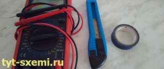
For diagnostics you will definitely need a multimeter.
Network wire
The first thing you need to check is the network cable. Test it with a multimeter and make sure it conducts current normally.
Start button
Next we check the button. Insert the multimeter contacts into the button terminals shown in the figure below and press it.
Then in another way and also click.
Now let's check the reverse. To do this, insert the multimeter electrodes as in the figure below, and then into the same holes on the reverse side.
After this, switch the reverse to another position and connect the multimeter from different sides to the contacts located opposite each other, as shown in the figures below.
If as a result of all these connections there was no ringing in at least one case, then the button needs to be changed. How to connect it if you suddenly disconnected all the contacts and don’t know where to insert what now, you can find out on this site in this article.
Inspection and replacement of brushes
Now inspect the commutator brushes and the commutator itself. The brushes should fit tightly to the commutator, and there should not be a large amount of carbon deposits and (or) graphite dust on it. If necessary, carbon deposits are removed with fine sandpaper, and hardened accumulations of graphite dust are scraped off with some pointed tool.
If the brushes are loose or worn out, they need to be replaced. Replacement is quite simple - you just need to remove them from the grooves. New brushes are selected in such a way that after installation they do not have even the slightest play, but can still move freely.
Faulty armature or stator windings
And the last thing to check electrically is the winding. Its damage can be in the form of an interturn short circuit, a wire short to ground, or a winding wire break.
To check the armature, set the multimeter to ohmmeter mode to values in the range of 20-200 Ohms. Now connect its electrodes one by one to adjacent contacts of the armature commutator. That is, to those contacts that are nearby. The readings should be approximately the same for each connection. If there is a deviation, then there is an interturn short circuit. If the multimeter does not show anything, then a break has occurred.
Next, check the armature for short circuit to ground. For convenience, set the multimeter to beep mode. To check, we connect one electrode to any metal part of the armature, and the second one in turn to each contact of the collector. The presence of a sound signal means that the winding is shorted to ground.
The stator is checked in ohmmeter mode at a value of 20-200 Ohms. First, we connect a multimeter to the ends of one winding, and then the other, and compare the readings. They should be the same. If not, then there is a short circuit between the turns.
When checking a short to ground, we connect one electrode of the multimeter, set to the sound signal position, to ground, and with the second we touch all the ends of the windings. If an audible signal appears, there is a short to ground.
Repair of windings is carried out by rewinding them. True, you don’t need to do this yourself - it’s better to leave it to specialists. The second option is a complete replacement of the stator or armature.
Failure of the mechanical part of the instrument
If electrical faults are difficult to identify, then dealing with mechanical breakdowns is much easier and cheaper. Mechanical defects can be identified even without the need to disassemble the instrument. If the drill cracks or the chuck does not rotate, but the characteristic sound of the engine is heard, it means there is a breakdown in the gearbox. When the attachment does not hold in the drill, there is a malfunction in the clamping jaws. Bearings can also fail and cannot be repaired and require comprehensive replacement.
Let's consider each type of malfunction, and the features of their identification and subsequent elimination.
- The bearings have failed.
Typically, bearings last quite a long time, and the main reason for their rapid failure is the lack of lubrication or its depletion. There are two types of bearing failures: complete destruction of the balls or wear. If completely destroyed, the part must be replaced. There are no difficulties when replacing bearings, so be sure to check their serviceability - Jamming of the gear unit - here breakdowns are associated with licking of the driven or driving gear.
Even during operation, a tooth may break off, which will ultimately lead not only to a decrease in productivity, but also to a complete jamming of the transmission mechanism. If the gearbox malfunctions, the gears must be replaced. It should be taken into account that on household tools the gearbox can be made of plastic gears. They must be replaced with similar ones, otherwise installing metal gears will lead to accelerated engine wear. - Repairing the impact mechanism of a drill - unlike a hammer drill, this mechanism on a drill has a primitive design.
The design consists of two parts, reminiscent of a friction clutch. Impacts are created by the movement of a toothed gear. The notches on the rotating gear mesh with teeth of a similar design on the housing, and as if jumping, clicks are created - they are also impacts. Malfunctions of the impact mechanism of a drill include the following: licking of jagged edges, which ultimately leads to a decrease in productivity. More often, the notches are licked off on the moving gear, which needs to be replaced. Another breakdown can occur when the shock mode of the limiter is not turned off. The reason is the wear of the metal ball, which, when the switch is moved, goes into the end of the shaft, thereby limiting the possibility of the gear teeth coming into contact with the protrusions on the body. To eliminate the malfunction, you should replace the ball in the design of the impact mechanism - Malfunction of the actuator - cartridge.
Drills use key type chucks, which are characterized by increased reliability and efficiency. The clamping jaw on this part may fail and should be replaced. Detailed instructions on how to remove, repair and replace the chuck on a drill
Bearings and cartridges are considered minor mechanical failures, and failure requires an appropriate approach. Even if diagnostics have shown that the gearbox does not need repair or replacement of parts, it must be dismantled, washed in gasoline and new lubricant applied. Such manipulations must be performed regularly, depending on the frequency of use of the power tool. A detailed description of how to repair the impact mechanism of a drill is described in the video report.
Learning to extend the life of a power tool from the moment of purchase
In order for the purchased power tool to serve for a long time and not fail at the most inopportune moment, it is necessary to ensure proper care from the very first day of purchase. This care includes doing the following:
- Store the tool exclusively in a dry and warm room. Exposure to moisture and low temperatures will lead to the formation of condensation and failure of the electrical parts of the tool.
- Do not use the tool for a long time under heavy loads, as this will lead to overheating of the windings and failure of the electric motor.
- The presence of an impact mode does not mean that you can drill holes in concrete and reinforced concrete with a drill every day. The impact drilling function is auxiliary and is intended for infrequent use. For such purposes it is necessary to use a hammer drill
- If the brushes spark strongly, it is necessary to replace them without waiting until the tool stops turning on altogether.
When purchasing, keep in mind that drills are available for household and professional purposes. If you choose a cheap household option, then you need to understand that such a tool is intended only for infrequent home use. Any repairs in the house using a household drill will cause the tool to fail. If you need a drill to make repairs in your home, then you need to choose only professional options.
Repairing a drill yourself is not at all difficult. The main thing is to approach this issue accordingly - start troubleshooting from small to large. After proper repair of a power tool, it will last for a very long time.
Algorithm for finding and eliminating electrical failures
Drill repair is carried out according to the principle “from simple to complex”. You should not immediately disassemble the tool down to the screw, and evaluate the condition of all components at the same time.
- The drill does not turn on. We start with the power cord (at a minimum, you should check the voltage in the outlet and extension cord before doing this). Having disassembled the case, we find the cable contacts and “ring” them using a multimeter.
Important! Do not test the supply wire with voltage applied! If the current-carrying wires are broken, you can get an electric shock or cause a short circuit.
We connect to the connector of the power plug and the opposite terminal of the cord. Then we bend the cable several times along its entire length. Losing contact or its complete absence indicates the presence of a break inside the insulation. If the fracture of the current-carrying core is close to the edge, the cable is cut and reconnected. It will just be a little shorter. If the break is in the middle of the length, it is better to replace the wire. Splicing will be unsafe.
- The cord is working - check the switch. We connect the multimeter to the terminals and press the key. A large current passes through the contacts, sparking occurs (especially when dust gets into the case). The contacts may simply oxidize. Carefully disassemble the switch body and clean the contact groups with fine sandpaper.
If metal parts break, it is better to purchase a new unit.
- If there is an additional contact group in the circuit between the switch and the electric motor (for example, a reverse switch or speed controller), we diagnose this unit as well.
- Next, we check the connecting wires from the switch to the motor brushes. If they are in order, we diagnose the brush assembly.
The springs must confidently press the brushes against the armature slats, and we check the carbon elements themselves for wear. If necessary, we replace: spare parts are included in the delivery set, or can be purchased in specialized stores. The armature contact lamellas may be oxidized or clogged. They can be gently cleaned with fine sandpaper.
- A more complex breakdown is the failure of the armature or stator windings. Using a multimeter, a short circuit is checked between the unit body and the winding contacts. Then the resistance is measured. The value should be the same on each winding, the spread of readings should not be more than 5%. Faulty windings must be rewound.
- You can do this yourself, or in a repair shop (in any case, it will be cheaper than buying a new engine).