Verification steps
Checking diodes with a multimeter
Diodes operate at low DC voltage. It is generated by blocks that are difficult to connect to. But part of the LED design is a semiconductor junction, due to which current is passed in a given direction. If there is enough current, the light bulb lights up.
Using a multimeter, it is easy to determine the health of the element. To do this, set the device to dialing mode, after which:
- The probes are thrown onto the area of the semiconductor that needs to be checked.
- The red probe with a positive charge is connected to the LED anode.
- A black probe with a negative charge is thrown onto the cathode.
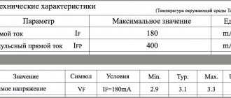
- The device screen should display an indicator of the voltage drop after the pn transition.
- The polarity of the connection changes. If there is no voltage drop, the diode is operational.
If the multimeter does not have a “Ring” mode, set it to 1 Ohm with the switch.
LED strip testing procedure
Each section from one point (plus and minus) to another is checked for integrity or breakage.
It is problematic to check the LED strip with a multi-meter, since it does not glow. Weak light occurs when testing in Hfe mode. Testing is also complicated by burnouts not of the diodes themselves, but of the contact tracks or current-carrying sections. To find out about a problem:
- Find conditional identical segments of 3 LEDs along the border of the contacts and the transverse strip.
- Touch the probes to each area in turn, applying current to the power contacts.
- Ring the power supply - it fails due to load drop.
Checking the resistance will provide a complete picture of the integrity of the LEDs.
Checking the LED strip
An LED strip consists of many LED devices combined into small sections. The LEDs are located sequentially within the sections, and the sections are located among each other. This ensures that the tape can be cut to the desired length. To test the LED strip, you need to apply current to the power wires. Everything is simple here - the tape is on, which means it is working . If the entire strip does not light up when power is applied, you need to check the resistance of the supply wires with a multimeter for an open circuit.
If, when connecting power to the LED strip, individual groups of LEDs do not light up, you need to ring them separately. In such a situation, you need to check them separately using a resistor, which is mounted in the circuit in front of each group. The reference value for checking should be the nominal resistance value.
Features of checking LED light bulbs
Using a multimeter, you can test color, standard and super-bright diodes.
Standard light bulb with E27 base
Checking an LED lamp
A similar lamp is used for household chandeliers or lamps. To check whether an LED is working or not working, you will need:
- Remove the diffuser from the light bulb using a plastic bank card placed between the element and the body.
- Carefully move the plastic card along the glue. A durable seam can be heated with a hair dryer.
- Open the board.
- Touch the elements with probes and wait until they glow with a dim glow.
If the diodes do not light, the light bulb is broken.
Super bright diodes
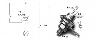
Checking a powerful diode
A garland is usually equipped with blue, yellow or white LEDs. The test is carried out without probes using transistor sockets according to the following algorithm:
- Determine the pinout of the SMD.
- Find 8 sockets at the bottom of the device - 4 left ones for PNP transistors and 4 right ones for NPN transistors.
- Place the probes by inserting the anode into hole E and the cathode into hole C.
- Open the PNP element by applying a positive charge to the emitter E. A working LED will light up.
- Change the polarity of transistors for NPN. The anode is placed on C, the cathode - on E.
Transistor sockets are useful for testing diodes with long contacts without solder.
Checking LED lamps
For the convenience of consumers, the production of lamps based on LEDs has now been launched, which have a geometric configuration similar to the already familiar incandescent lamps. This makes it possible to install LED lamps in ordinary lamps powered by a 220 V network.
A special current converter – driver – is built into the design of such a lamp. This device is assembled from parts that have parameters that differ in each individual model. This circumstance makes it impossible to use this type of diagnostics, such as checking an LED lamp with a multimeter.
The LED lamp is tested using a special tester. It is a device, inside of which a circuit is assembled that allows you to check the performance of lamps of various types. For this purpose, the body has several connectors for the most commonly used lamp bases. The test result is displayed in the form of a sound signal.
How to check an LED spotlight
Internal structure of the spotlight
The LED is checked after determining the type of element. The following are installed on the lanterns:
- a board with small SMDs, which are checked by continuity in the same way as a standard light bulb;
- a large yellow element operating on a voltage of 10-30 V.
The voltage of a large element is high for the tester, so the operability of the element can only be determined by the driver. It must match the performance of the diode.
Nuances of testing infrared diodes
Testing an Infrared LED
The infrared LED produces invisible radiation, so it is important to monitor the readings on the multimeter display. The probes are installed by applying plus to the anode and minus to the cathode. By touching the probes to the working IR diode, you can see the number 1000 on the screen. When the polarity is changed, 1 is displayed.
To accurately check the infrared diode with transistor sockets, a smartphone camera or digital device is used. The IR LED will need to be placed in the transistor sockets and the camera pointed at it. Serviceability is indicated by a glowing blurry spot on the gadget’s display.
Soldering a parallel red LED glow will clearly reflect the performance of the diode. If a signal is supplied to the element at the moment of flickering, it should be replaced. If the backlight does not work, the remote control is faulty.
Checking the LED Bridge
Checking the diode bridge
The diode bridge is an assembly of 4 elements. They are connected so that AC voltage is supplied to two of the 4 terminals, turns into DC voltage and is removed from the other 2 terminals. Zener diodes equalize voltage within a narrow range.
You can ring the LED bridge like this:
- Find which pin to connect the multimeter to by making a conditional numbering.
- Ring the first diode by placing probes on pins 1 and 2.
- Test the second LED by connecting probes to pins 2 and 3.
- Measure the parameters of the third diode by connecting probes to pins 1 and 4.
- Determine the serviceability of the fourth element by placing probes on pins 4 and 3.
- View the readings on the scoreboard.
Voltage stability is checked in the maximum range mode - 220 V. It is increased gradually and stopped supplying until current flows through the circuit.
You will need to place the black probe on the anode, the red one on the cathode, and then connect the anode to the current limiting resistor, and the cathode to the power source.
How to test an LED with your own hands for functionality
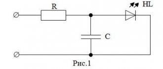
To test a diode light bulb, you first need to determine what will be used to test it. You will need to purchase a power supply (PS) with an operating voltage ranging from 6.0 to 10.0 V. There is no need to rush to connect a light diode to it.
Checking the current source
The next step is to purchase a resistor with a value that limits the current, with a voltage in the range of 6-12 mA. The diode is removed from the circuit for testing. Then when in an electrical circuit, with a resistor connected in series to the LED diode, there is a voltage drop of approximately 2 V, then the resistor is from 3 to 10 V. In the case of using a 5/12 V IP, for an electric current of 5 mA, according to Ohm triangle, you will need a resistance of 0.600 kOhm or 2 kOhm, respectively. Select a limiting value, for example, 0.560 kOhm and 2.1 kOhm for a 5/12 V power supply. Connect the LED through a resistor in series with the power supply.
You might be interested in Resistance meters
Important! The extended LED leg connected to the smaller internal electrode is the anode, it is connected to the positive terminal of the IP. The small leg goes to the negative terminal of the IP. The resistance is connected to the elongated positive leg of the light diode, and the assembled circuit is connected to the power supply - to the short “-” leg. For resistance - “+„. In the case when the legs are removed and no one can find out which of them was longer, then “-” is connected to the electrode, which looks largest through the lens. If the light diode is operational, it will turn on.
Specifics of the dialing mode
Symbols on the multimeter panel
A multimeter is a universal tester that can be used to test light-emitting diodes and other elements. During operation, the device makes a squeaking or ringing sound, which is why the mode is called ringing.
Operating a multimeter in dialing mode has several features:
- the switch is placed to check the diodes, the probes are thrown onto the contacts;
- the polarity of the terminals is determined, but if it could not be detected, the LED light source will not fail;
- when the probes are correctly connected to the contacts and the correct polarity, the working diode will light up;
- during the dialing process, no current with a large value is supplied, so the backlight of the diodes is visible only in a darkened room;
- if there are difficulties with dimming the lighting, look at the device display - the indicator of the working SMD is different from 1;
- high-power LEDs without desoldering are tested after adding adapters.
Before starting work in ringing mode, determine the anode and cathode of the light source being tested.
Testing LEDs in dialing mode
A multimeter is a universal meter that allows you to check the serviceability of almost any electrical device or element. To check a light-emitting diode using a tester, it is necessary that the device can switch to diode testing mode, which is most often called continuity testing.
Checking the serviceability of the LED with a multimeter is carried out in the following order:
- Set the tester switch to diode test mode.
- Connect the multimeter probes to the contacts of the element being tested.
- When connecting an LED, you should take into account the polarity of its terminals (the black probe of the measuring device is connected to the cathode, and the red one to the anode). However, if the exact location of the poles is unknown, then there is nothing wrong with an incorrect connection, and the LED will not fail in this case.
If the probes are connected to the contacts incorrectly, then the initial readings on the tester display will not change. If the polarity is not reversed, the working diode will light up.
- The continuity current is small and is not enough for the LED to work at full capacity. Therefore, you can see the glow of the element by slightly darkening the room.
- If there is no way to dim the lighting, you need to look at the readings of the multimeter. When checking the working diode, the values on the device display will differ from one.
Visually checking the LEDs in the video:
Using this method, you can check even a powerful diode for functionality. The disadvantage of this method is that it will not be possible to diagnose the elements without removing them from the circuit. To test LEDs in a circuit, adapters must be connected to the probes.
Sometimes the serviceability of a part is checked by measuring the resistance, but this method is not widely used because to use it, you need to know the technical parameters of the diode.
Checking LEDs without desoldering
Probes for a multimeter with adapters
You can check an LED lamp without desoldering its diode elements. You will need an adapter, which you can make yourself from paper clips, individual wire strands, pieces of sewing needles, and twisted pair wiring. The selected product is soldered to the meter probes. A PCB gasket is made between the parts of the adapter, and then the entire structure is wrapped with insulating tape.
Multimeter probes with an adapter are connected to the contacts of a light-emitting diode or to PNP blocks. Testing is carried out sequentially for each element.
Checking the functionality of light-emitting diodes in a flashlight
Testing the LED flashlight board
Testing a standard flashlight is a clear example of work for which you do not need to solder the elements. To find out if the LED sources are working, you need to:
- Disassemble the flashlight and remove the board with LEDs from it.
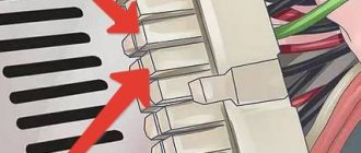
- Without removing the solder, place the probes on the contacts of the PNP connector, observing the polarity.
- Set the switch to dial.
- Look at the scoreboard and the lights.
- Determine whether the circuit is working properly by checking its resistance. A resistance value of zero when connected in parallel indicates a malfunction of one LED.
Test each diode separately.
Available materials for testing
In addition to a multimeter, a lamp, flashlight or LED spotlight can be checked:
- Battery. A CR2032 battery is suitable for the computer motherboard. Its voltage of 3 V is enough for all types of diodes.
- A 4.5 and 9 V battery together with a ballast resistor. It will give a voltage drop to a safe value. 750 Ohms are supplied to the Krona, and from 150 to 200 Ohms to 4.5 V products.
- Battery from a radio bell or remote control. An LED strip is tested with a 12 V element. Its contacts are thrown onto the poles, after which points with burnt-out LEDs are found. Connectors are tested in the same way.
- A special LED tester operating on the basis of AA batteries with a parallel connection.
- An old charger from which the plug on the phone is removed and the contact is protected. The red wire will be positive and will go to the anode. Black is used as a minus and is connected to the cathode. If there is enough voltage, the LED lights up.
Testing a UV diode is complicated by its sensitivity to high voltage. It is supplied with a nominal value of no more than 3.4-4 V.
The LED strip lights up dimly.
Is your LED strip working fine, but at one end the brightness is noticeably lower? Why does the LED strip light up dimly? This is a common problem with low quality LED strips and the main cause is voltage drop. Voltage drop is mainly caused by excessive electrical current for a given circuit design, or excessive resistance in the circuit, or a combination of both.
p, blockquote 14,0,0,0,0 —>
Check your diagram.
p, blockquote 15,0,0,0,0 —>
Most LED strips will have a maximum run length based on wattage per foot and internal circuit design. Since each section of the LED strip must carry current for all of the "downstream" segments of the LED strip, an LED strip connection that is too long will exceed the power rating for the LED strip sections closest to the power source.
p, blockquote 16,0,0,0,0 —>
The most immediate consequence of overloading an LED strip with too much power is a voltage drop, causing the voltage supplied to each section of the LED strip to gradually decrease as it moves away from the power source. The reason for the voltage drop is the internal resistance in the copper traces of the PCB.
p, blockquote 17,0,0,0,0 —>
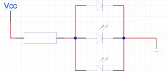
Don't forget that the wires connecting or between LED strips also have internal resistance, and using wires that are not thick enough can also cause excessive voltage drop. You may be able to change your circuit so that it is configured in "parallel" rather than "series".
Tips and tricks
When diagnosing LED devices, the following factors must be taken into account:
- if the voltage rating is at the limit, and the luminous flux does not appear, you can briefly increase the current;
- when high power is supplied, the LED source heats up;
- the normal heating temperature of the diode is from 70 to 75 degrees (do not burn your palm when touched);
- using a battery, you can additionally set the diode connection resistance;
- if the polarity is changed, even a working element will not have a backlight;
- the optimal material for a homemade probe is nickel-plated needles, which are easy and quick to solder;
- A working IR LED lights up when the radiation is directed at the sensitive area.
Testing LED light sources is easy if you know how to use a multimeter. The user needs to prepare the conditions for testing - select the polarity, design probes or adapters, make special contacts.