The Basics of Soft Start
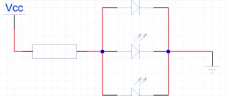
Let's start with the basics and remember what an RC circuit is and how it is related to the smooth ignition and decay of the LED. Look at the diagram.
It contains only three components:
- R – resistor;
- C – capacitor;
- HL1 – backlight (LED).
The first two components make up the RC circuit (the product of resistance and capacitance). Increasing the resistance R and capacitance C of the capacitor increases the ignition time of the LED. When decreasing, the opposite is true.
We will not delve into the basics of electronics and consider how physical processes (more precisely, current) occur in this circuit. It is enough to know that it underlies the operation of all smooth ignition and extinction devices.
The considered principle of RC delay underlies all solutions for smooth turning on and off of LEDs.
Buy or make it yourself
The first question that arises when it is necessary to include a soft ignition module for LEDs in the circuit is whether to make it yourself or buy it. Naturally, it is easier to purchase a ready-made block with specified parameters. However, this method of solving the problem has one serious disadvantage - the price. When making it yourself, the cost of such a device will decrease several times. In addition, the assembly process does not take much time. In addition, there are proven options for the device - all that remains is to acquire the necessary components and equipment and connect them correctly, in accordance with the instructions.
Note! LED lighting is widely used in cars. For example, these could be daytime running lights and interior lighting. The inclusion of a smooth ignition block for LED lamps allows, in the first case, to significantly extend the life of the optics, and in the second, to prevent the driver and passengers from being blinded by the sudden switching on of a light bulb in the cabin, which makes the lighting system more visually comfortable.
DIY daytime running lights: diagram
According to the requirements, daytime running lights must turn on automatically when the engine is started. They must be turned on and off without the help of an additional tool (that is, directly from inside the car).
To do this, the DRL is switched to the voltage supply unit for the central headlights. The most common legal installation scheme is a connection scheme in which the daytime lights are turned on together with the headlights.
It should be remembered that installing DRLs yourself must adhere to the requirements of GOST R 41.48-2004, which oblige any change in the description to be brought to the attention of the Certification Body.
This body can make two verdicts:
- come to the conclusion that the vehicle complies with standard requirements and the changes made will not have a negative impact
- request an additional protocol from the laboratory that is authorized to conduct tests
Smooth load switching on and off
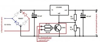
Probably many people wanted to add something new to their car, today I will tell you how to do this without special costs and technical changes in the design of the car. The device that I want to present to you today is not a large circuit for adjusting the startup and shutdown of the load, in our case, lighting fixtures, interior lighting, dashboard lighting, etc. Our device will allow you to smoothly turn on and off any of the listed loads. Agree, it’s much more pleasant when, when you turn on the ignition, we see not a sharp switching on of the dashboard backlight, but a smooth ignition. The same can be said about interior lighting and lighting fixtures. From words, let's get down to business and before starting assembly, I suggest you familiarize yourself with the diagram:
First, I’ll tell you how it connects. We need to supply VCC+ with a constant 12 V from the battery, which will power our load. We connect to REM those 12 V that appear after turning on the ignition, it is they that will initiate ignition and when they disappear, the circuit will turn off the lighting. Accordingly, we connect our load (in my case, LEDs) to the LED+ LED- contacts. I used BC817 (analogue of KT503V) as transistor T1; I took IRF9540S as T2. If you want to increase the ignition time, you need to increase the R2 value; to decrease it, lower it accordingly. To control the damping time, a similar operation must be done with resistor R3. Now you can proceed to assembly. To reduce the size of the device, I used surface mounting. Here is the entire set of elements that I needed:
The boards were manufactured using “LUT” technology from single-sided PCB.
We finally got such a compact device that can add aesthetics to our car.
Expenses:1. Resistors 0.25 rub. x4 = 1 Rub2. BC817 = 3 rub.3. IRF9540S = 35 RUR4. Capacitor 8 RUR 5. Terminals 21.5
Result: For only 70 rubles. we get quite an interesting device. PS Video of the device in action:
Scheme
Since the device for smoothly switching on incandescent and halogen lamps is not particularly difficult from a circuit design point of view, you can assemble it yourself. The assembly process can be carried out:
- hanging installation;
- on a breadboard;
- on the printed circuit board.
And depending on your skills and capabilities, the most reliable option will be the one on a printed circuit board; in this case, it is better to stay away from wall-mounted installation if you do not know the specifics of such installation in 220 V circuits.
Smooth switching on of 220 V lamps: thyristor circuit
The first diagram is shown in the figure below. Its main functional element is a thyristor connected in the arms of the diode bridge. The denominations of all elements are signed. If you use it as a smooth ignition for a floor lamp, table lamp or other portable lamp, it is convenient to enclose it in a housing; a distribution box for external installation is suitable. At the exit, install a socket for connecting a lamp. In fact, this is a regular dimmer, and there is no soft start as such. You simply turn the potentiometer knob, gradually increasing the voltage across the lamp. By the way, such an attachment is also suitable for adjusting the power of a soldering iron or other electrical appliances (stove, commutator motor, etc.).
Smooth switching on of 220 V lamps: triac circuit
You can reduce the number of parts and assemble the same circuit that is installed in proprietary protection units. It is shown in the figure below.
The larger the time constant R2С1 of the chain, the longer the ignition takes
To increase the time, you need to increase the capacitance C1, please note - this is a polar or electrolytic capacitor. Capacitor C2 must withstand a voltage of at least 400 V - this is a non-polar capacitor
To increase the power of the connected lamps, change the triac VS1 to any current suitable for your load.
Choke L1 is a filter element; it is needed to reduce interference in the network from turning on the triac. It is not necessary to use it; it does not affect the operation of the circuit.
When SA1 (switch) turns on, current begins to flow through the lamp, inductor and capacitor C2. Due to the reactance of the capacitor, the current flows through the lamp is small. When the voltage to which C1 is charged reaches the opening threshold of the triac, current will flow through it, the lamp will turn on at full heat.
Popular articles Weaving a basket from a magazine vine
Smooth switching on of 220 V lamps: circuit based on IC KR1182PM1
There is also an option for smooth start-up using the KR1182PM1 microcircuit; it provides smooth start-up of lamps and other loads with a power of up to 150 W. You will find a detailed description of this chip here:
and below is a diagram of the device, it is extremely simple:
Or here is its modernized version to enable a powerful load:
Additionally, a BTA 16–600 thyristor is installed, it is designed for a current of up to 16 A and a voltage of up to 600 V, this can be seen from the markings, but you can take any other one. Thus, you can turn on a load of up to 3.5 kW.
Smooth turning on and off of LEDs: ignition circuits
In some cases, it is necessary to implement a circuit for smoothly turning on or off an LED. This solution is especially in demand in organizing design solutions.
To implement the plan, there are two solutions. The first is to buy a ready-made ignition unit in a store. The second is making a block with your own hands.
In the article, we will find out why it is worth resorting to the second option, and also analyze the most popular schemes.
Buy or make it yourself?
If you need it urgently or don’t have the desire or time to assemble a block for smooth switching on of LEDs with your own hands, then you can buy a ready-made device in a store. The only negative is the price. The cost of some products, depending on the parameters and manufacturer, can exceed several times the cost of a device made by yourself.
If you have time and especially desire, then you should pay attention to long-developed and time-tested schemes for smoothly turning on and off LEDs
What do you need
In order to assemble a circuit for smooth ignition of LEDs, first of all, you will need a small set of radio amateurs, both skills and tools:
- soldering iron and solder;
- textolite for the board;
- body of the future device;
- a set of semiconductor devices (resistors, transistors, capacitors, LEDs, diodes, etc.);
- desire and time;
As you can see from the list, nothing special or complicated is required.
The Basics of Soft Start
Let's start with the basics and remember what an RC circuit is and how it is related to the smooth ignition and decay of the LED. Look at the diagram.
It contains only three components:
- R – resistor;
- C – capacitor;
- HL1 – backlight (LED).
The first two components make up the RC circuit (the product of resistance and capacitance). Increasing the resistance R and capacitance C of the capacitor increases the ignition time of the LED. When decreasing, the opposite is true.
We will not delve into the basics of electronics and consider how physical processes (more precisely, current) occur in this circuit. It is enough to know that it underlies the operation of all smooth ignition and extinction devices.
The considered principle of RC delay underlies all solutions for smooth turning on and off of LEDs.
Schemes for smooth switching on and off of LEDs
There is no point in disassembling cumbersome circuits, because... Most problems can be solved by simple devices operating on elementary circuits. Let's consider one of these schemes for smoothly turning on and off LEDs. Despite its simplicity, it has a number of advantages, high reliability and low cost.
Consists of the following parts:
- VT1 – field effect transistor IRF540;
- C1 – capacitor with a capacity of 220 mF and a voltage of 16V;
- R1, R2, R3 – resistors with a nominal value of 10, 22, 40 kOm, respectively;
- LED – light-emitting diode.
Operates from a voltage of 12 Volts according to the following algorithm:
- When the circuit is connected to the power circuit, current flows through R2.
- At this time, C1 gains capacity (charges), which ensures the gradual opening of the field switch VT
- Increasing gate current (pin 1) flows through R1, and causes the field drain VT to gradually open
- The current goes to the source of the same field switch VT1 and then to the LED.
- The LED gradually increases its light emission.
Self-production
If you know all the details, the work will take no more than 1 hour. It is necessary to select the necessary elements and equipment in order to make high-quality connections.
What you will need
You will need:
- solder and soldering iron;
- LEDs;
- resistors;
- capacitor;
- transistors;
- housing to accommodate the necessary elements;
- a piece of PCB for the board.
Fig. 2 – textolite sheet for soldering.
Capacitor capacity – 220 mF. Voltage no more than 16 V. Resistor ratings:
- R1 – 12 kOm;
- R2 – 22 kOm;
- R3 – 40 kOm.
When assembling, it is advisable to use an IRF540 field-effect transistor.
Step-by-step instruction
The first stage is making the board. It is necessary to mark the boundaries on the textolite and cut the sheet along the contours. Next, sand the workpiece with sandpaper (grit P 800-1000).
Next, print the diagram (layer with tracks). A laser printer is used for this. The diagram can be found on the Internet. An A4 sheet is glued to glossy paper (for example, from a magazine) with masking tape. The image is then printed.
Fig. 3 – diagram after printing.
The diagram is glued onto the sheet, heated with an iron. To cool the board, place it in cold water for a few minutes and then remove the paper. If it does not peel off immediately, you need to clean it gradually.
Using double-sided tape, glue the board to foam plastic of the same size and place it in a ferric chloride solution for 5-7 minutes. In order not to overexpose the board, you need to periodically take it out and check its condition. To speed up the etching process, you can shake the container with liquid. When excess copper is removed, the board must be washed in water.
Fig. 4 – board in ferric chloride solution.
The next step is to clean the tracks with sandpaper and you can start drilling holes for installing board elements. Next, the board needs to be tinned. To do this, it is lubricated with flux, after which it is tinned with a soldering iron. To avoid overheating or breaking the circuit, the soldering iron must be constantly in motion .
Fig. 5 – board prepared for installation of elements.
The next step is to install the elements according to the diagram. To make it clearer, you can print out the same diagram on paper, but with all the necessary symbols. After soldering, it is necessary to completely get rid of the flux. To do this, the board can be wiped with solvent 646, then cleaned with a toothbrush. When the block dries well, it needs to be checked. To do this, a permanent plus and minus must be connected to the power supply. At the same time, you should not touch the control plus.
Fig.6 – checking the correct operation of the board.
Instead of LEDs, it is better to use a multimeter to check. If voltage occurs, it means the board is shorting. This is possible due to flux residues. To get rid of the problem, just clean the board again. If there is no voltage, the unit is ready for use.
Smooth turning on and off of LEDs
This article will consider several options for implementing the idea of smoothly turning on and off the LEDs for the instrument panel illumination, interior light, and in some cases, more powerful consumers - dimensions, low beam and the like. If your instrument panel is illuminated using LEDs, when the lights are turned on, the backlighting of the instruments and buttons on the panel will light up smoothly, which looks quite impressive. The same can be said about the interior lighting, which will gradually light up and fade out smoothly after closing the car doors. In general, this is a good option for tuning the backlight :).
Control circuit for smooth switching on and off of the load, controlled by plus.
This circuit can be used to smoothly turn on the LED backlight of a car dashboard.
This circuit can also be used for smooth ignition of standard incandescent lamps with low-power coils. In this case, the transistor must be placed on a radiator with a dissipation area of about 50 square meters. cm.
The scheme works as follows. The control signal is supplied through 1N4148 diodes when voltage is applied to “plus” when the side lights and ignition are turned on. When any of them is turned on, current is supplied through a 4.7 kOhm resistor to the base of the KT503 transistor. At the same time, the transistor opens, and through it and the 120 kOhm resistor the capacitor begins to charge. The voltage on the capacitor gradually increases, and then through a 10 kOhm resistor it is supplied to the input of the field-effect transistor IRF9540. The transistor gradually opens, gradually increasing the voltage at the output of the circuit. When the control voltage is removed, the KT503 transistor closes. The capacitor is discharged to the input of the field-effect transistor IRF9540 through a 51 kOhm resistor. After the capacitor discharge process is completed, the circuit stops consuming current and goes into standby mode. The current consumption in this mode is negligible. If necessary, you can change the ignition and decay time of the controlled element (LEDs or lamps) by selecting the resistance values and capacitance of the 220 μF capacitor.
With proper assembly and serviceable parts, this circuit does not require additional settings.
Here is a version of a printed circuit board for placing the parts of this circuit:
Scheme of smooth switching on and off of LEDs.
This circuit allows you to smoothly turn on and off the LEDs, as well as reduce the brightness of the backlight when the dimensions are turned on. The latter function can be useful in the case of excessively bright backlighting, when in the dark the instrument lighting begins to dazzle and distract the driver.
Popular articles Congratulations on March 8 in verse and prose
The circuit uses a KT827 transistor. Variable resistance R2 is used to set the brightness of the backlight when the dimensions are on. By selecting the capacitance of the capacitor, you can regulate the time of ignition and extinction of the LEDs.
In order to implement the function of dimming the backlight when the lights are turned on, you need to install a double headlight switch or use a relay that would be activated when the lights are turned on and close the switch contacts.
Smooth turning off of LEDs.
The simplest circuit for smooth fading of the VD1 LED. Well suited for implementing the function of smooth fading of interior light after closing the doors.
Almost any diode VD2 will do; the current through it is small. The polarity of the diode is determined in accordance with the figure.
Capacitor C1 is electrolytic, large capacity, the capacity is selected individually. The larger the capacitance, the longer the LED lights up after the power is turned off, but you should not install a capacitor with too large a capacitance, since the contacts of the limit switches will burn due to the large charging current of the capacitor. In addition, the larger the capacitance, the more massive the capacitor itself, and problems with its placement may arise. Recommended capacitance is 2200 µF. With such a capacity, the backlight fades out within 3-6 seconds. The capacitor must be designed for a voltage of at least 25V
IMPORTANT! When installing the capacitor, observe the polarity! If the connection polarity is incorrect, the electrolytic capacitor may explode!
Methods for implementing soft start
Before deciding on ways to implement a soft launch, it is necessary to find out how UVPLs work. The principle of operation of devices of this type is based on the ability to first lower and then gradually increase the voltage to the optimal value. The device is connected to the wire gap between the lamp (lamp) and the switch.
When voltage is applied, its value increases due to soft start circuits. They can be assembled using transistors, triacs or thyristors using PIR (phase-pulse regulator) circuits. The rate of voltage increase can vary within a few seconds: much depends on the circuit in which the device was assembled. The load power most often does not exceed 1400 W.
power unit
The protection unit acts as a device that ensures smooth startup. Using the device simultaneously with the lamp allows you to gradually reduce the voltage supplied to the lighting device. In this case, the tungsten filament does not experience much stress, which allows it to prolong its service life.
As electrical current passes through the block, the voltage drops (from 220V to 170V). The speed varies within 2-4 seconds. Using the protection unit as intended leads to a reduction in light flux by 50-60%. Uniel Upb-200W-BL devices can withstand up to 220 V, so it is necessary to connect light bulbs of the same power to them.
The device can be installed next to switches or lighting devices.
Soft start device
The mechanism of operation of the device for smooth switching on of incandescent lamps (UPVL) is the same as that of protective blocks. The device has a significant advantage - its small size, so it can be installed in a socket box (behind the switch), inside a distribution box and a ceiling lamp (under the hood). The UPVL connection must be carried out sequentially, starting from connecting the device to the phase conductor.
Dimming
Dimmers have the ability to regulate electric current, so these devices are often installed in residential areas. The devices change the brightness of the light produced by halogen, LED or incandescent lamps.
A rheostat or variable resistor is considered the simplest dimmer. The device was invented in 1847 by Christian Poggendorff. With its help, you can regulate the strength of electric current and voltage. The device consists of several parts:
- conductor;
- resistance regulator.
The resistance changes smoothly. To reduce the brightness of the light, the voltage is reduced. In this case, the values indicating current strength and resistance will be high, which will cause overheating of the lighting fixture.
Dimmers also include autotransformers. These devices have a fairly high efficiency. The voltage is supplied undistorted, the optimal frequency is no more than 50 Hz. A significant disadvantage of an autotransformer is its heavy weight. To manage them, a person must make every effort.
The electronic version is the simplest and most accessible device with which you can control the current strength. The main part of the compact device is a switch (key), which is controlled by thyristor, triac and transistor semiconductors.
There are several ways to adjust the dimmer:
- along the leading edge;
- along the trailing edge.
The voltage supplied to incandescent lamps can be adjusted in both ways.
Minus control
The above translated diagrams are perfect for use in a car. However, the complexity of some electrical circuits lies in the fact that some of the contacts are connected to the positive, and some to the negative (common wire or body). To control the above circuit by minus power, it needs to be slightly modified. The transistor needs to be replaced with a p-channel one, for example IRF9540N. Connect the negative terminal of the capacitor to the common point of three resistors, and connect the positive terminal to the source of VT1. The modified circuit will have power with reverse polarity, and the control positive contact will be replaced by a negative one.
Source
Methods for implementing soft start
Before deciding on ways to implement a soft launch, it is necessary to find out how UVPLs work. The principle of operation of devices of this type is based on the ability to first lower and then gradually increase the voltage to the optimal value. The device is connected to the wire gap between the lamp (lamp) and the switch.
When voltage is applied, its value increases due to soft start circuits. They can be assembled using transistors, triacs or thyristors using PIR (phase-pulse regulator) circuits. The rate of voltage increase can vary within a few seconds: much depends on the circuit in which the device was assembled. The load power most often does not exceed 1400 W.
power unit
The protection unit acts as a device that ensures smooth startup. Using the device simultaneously with the lamp allows you to gradually reduce the voltage supplied to the lighting device. In this case, the tungsten filament does not experience much stress, which allows it to prolong its service life.
As electrical current passes through the block, the voltage drops (from 220V to 170V). The speed varies within 2-4 seconds. Using the protection unit as intended leads to a reduction in light flux by 50-60%. Uniel Upb-200W-BL devices can withstand up to 220 V, so it is necessary to connect light bulbs of the same power to them.
The device can be installed next to switches or lighting devices.
Soft start device
The mechanism of operation of the device for smooth switching on of incandescent lamps (UPVL) is the same as that of protective blocks. The device has a significant advantage - its small size, so it can be installed in a socket box (behind the switch), inside a distribution box and a ceiling lamp (under the hood). The UPVL connection must be carried out sequentially, starting from connecting the device to the phase conductor.
Dimming
Dimmers have the ability to regulate electric current, so these devices are often installed in residential areas. The devices change the brightness of the light produced by halogen, LED or incandescent lamps.
A rheostat or variable resistor is considered the simplest dimmer. The device was invented in 1847 by Christian Poggendorff. With its help, you can regulate the strength of electric current and voltage. The device consists of several parts:
- conductor;
- resistance regulator.
The resistance changes smoothly. To reduce the brightness of the light, the voltage is reduced. In this case, the values indicating current strength and resistance will be high, which will cause overheating of the lighting fixture.
Popular articles Fluffy pompom wreath
Dimmers also include autotransformers. These devices have a fairly high efficiency. The voltage is supplied undistorted, the optimal frequency is no more than 50 Hz. A significant disadvantage of an autotransformer is its heavy weight. To manage them, a person must make every effort.
The electronic version is the simplest and most accessible device with which you can control the current strength. The main part of the compact device is a switch (key), which is controlled by thyristor, triac and transistor semiconductors.
There are several ways to adjust the dimmer:
- along the leading edge;
- along the trailing edge.
The voltage supplied to incandescent lamps can be adjusted in both ways.
Schemes for smooth switching on and off of LEDs
There are two popular and self-manufacturing options for soft ignition circuits for LEDs:
- The simplest.
- With function for setting the start period.
Let's consider what elements they consist of, what is the algorithm of their operation and the main features.
A simple scheme for smoothly turning on and off LEDs
Only at first glance, the smooth ignition diagram presented below may seem simplified. In fact, it is very reliable, inexpensive and has many advantages.
It is based on the following components:
- IRF540 is a field-effect transistor (VT1).
- Capacitive capacitor 220 mF, rated at 16 volts (C1).
- A chain of resistors of 12, 22 and 40 kiloOhms (R1, R2, R3).
- Led crystal.
The device operates from a 12 V DC power supply according to the following principle:
- When the circuit is energized, current begins to flow through block R2.
- Thanks to this, element C1 is gradually charged (the capacity rating increases), which in turn contributes to the slow opening of the VT module.
- The increasing potential at pin 1 (field gate) provokes the flow of current through R1, which contributes to the gradual opening of pin 2 (VT drain).
- As a result, the current passes to the source of the field unit and to the load and ensures smooth ignition of the LED.
The process of extinction of the ice element follows the reverse principle - after removing the power (opening the “control plus”). In this case, the capacitor module, gradually discharging, transfers the capacitance potential to blocks R1 and R2. The speed of the process is regulated by the rating of the element R3.
The main element in the smooth ignition system for LEDs is the MOSFET IRF540 n-channel field-effect transistor (as an option, you can use the Russian model KP540).
The remaining components relate to the harness and are of secondary importance. Therefore, it would be useful to present its main parameters here:
- Drain current is within 23A.
- The polarity value is n.
- Drain-source voltage rating is 100V.
Improved version with the ability to customize the time
Often there is a need to change the period of smooth ignition of LEDs. The scheme discussed above does not provide such an opportunity. Therefore, two more semiconductor components need to be introduced into it - R4 and R5. With their help, you can set resistance parameters and thereby control the ignition speed of the diodes.
The above versions of the circuits assume control by plus, but in some situations control by minus is required. In this case, the system will have reverse polarity. Therefore, you need to put a capacitor in it in reverse - so that the positive charge goes to the transistor source. In addition, it is necessary to replace the transistor itself; now it must be a p-channel type, for example, IRF9540N.
Features of the circuit with time settings
To be able to independently adjust the duration of switching off and switching on, resistors are added to the circuit.
Fig. 7 - circuit with added resistors R4 and R5.
To smoothly turn on the LEDs, it is recommended to use resistors R3 and R2 of small values. The parameters of resistors R4 and R5 make it possible to control the speed of attenuation and switching on.
We recommend watching a series of thematic videos.
Smooth turning on and off of LEDs
There are cases when it is necessary to ensure smooth switching on of LEDs used for lighting or backlighting, and in some cases, switching off. Smooth ignition may be required for various reasons.
Firstly, when turned on instantly, the light “hits the eyes” hard and makes us squint and squint, waiting for our eyes to get used to the new level of brightness. This effect is associated with the inertia of the eye's accommodation process and, of course, occurs not only when LEDs are turned on, but also any other light sources.
It’s just that in the case of LEDs it is aggravated by the fact that the emitting surface is very small. In scientific terms, the light source has a very high overall brightness.
Secondly, purely aesthetic goals may be pursued: you must agree that a light that smoothly lights up or goes out is beautiful. The LED power supply circuit must be improved properly. Let's look at two different ways to smoothly turn on and off LEDs.
RC delay
The first thing that should come to mind for a person familiar with electrical engineering is introducing a delay by including an RC circuit in the LED power supply circuit: a resistor and a capacitor. The diagram is shown in Fig. 1. When voltage is applied to the input, the voltage on the capacitor, as it charges, will increase over a time approximately equal to 5τ, where τ=RC is the time constant.
That is, in simple terms, the time the light is turned on will be determined by the product of the capacitance of the capacitor and the resistance of the resistor. Accordingly, the greater the capacitance and resistance, the longer it will take for the LEDs to ignite. When the power is turned off, the capacitor will discharge to the LEDs.
The time during which smooth decay will occur will also be determined by τ, but in this case, instead of R, the dynamic resistance of the LEDs will be included in the product. For example, a 2200 uF capacitor and a 1 kOhm resistor will theoretically “stretch” the turn-on time by 2.2 seconds.
The simplest diagram presented makes it possible to understand the operating principle of this method well, but it is of little use for practical implementation. To obtain a working solution, we will improve it by introducing several additional elements (Fig. 2).
The circuit works as follows: when the power is turned on, capacitor C1 is charged through resistor R2, transistor VT1, as the gate voltage changes, reduces the resistance of its channel, thereby increasing the current through the LED. Turning off the power will cause the capacitor to discharge through the LEDs and resistor R1.
Let's turn on our brains...
If the circuit needs to provide greater flexibility and functionality, for example, without changing the hardware, we want to get several operating modes and set the ignition and decay times more accurately, then it’s time to include a microcontroller and an integrated LED driver with a control input in the circuit.
The microcontroller is capable of accurately counting the required time intervals and issuing commands to the driver control input in the form of PWM. Switching operating modes can be provided in advance and a corresponding button can be displayed for this. We only need to formulate what we want to get and write the appropriate program.
An example is the LDD-H high-power LED driver, which is available with current ratings from 300 to 1000 mA and has a PWM input. The connection diagram for specific drivers is usually given in the technical specifications. manufacturer's description (data sheet).
Scheme and principle of its operation
Let's consider one of the simplest options for a scheme for smoothly turning on and off LEDs controlled via the positive wire. In addition to ease of execution, this simplest scheme has high reliability and low cost. At the initial moment of time, when the supply voltage is applied, current begins to flow through resistor R2, and capacitor C1 is charged. The voltage across the capacitor cannot change instantly, which contributes to the smooth opening of transistor VT1. The rising gate current (pin 1) passes through R1 and leads to an increase in the positive potential at the drain of the field-effect transistor (pin 2). As a result, the LED load is switched on smoothly.