How does a hand-held flashlight work?
The design of the flashlight is simple. It consists of a battery compartment and a compartment with an emitter and reflector, as well as a power switch.
Composition of a hand lamp.
This content has not changed since the invention of the pocket electric lamp, although the element base has changed dramatically.
LED flashlight circuit
In modern conditions, incandescent lamps are being intensively replaced by LEDs. They could not withstand the competition due to lower efficiency and shorter service life. Semiconductor light-emitting elements have also become widespread in portable hand-held lamps. But simply replacing a light bulb with an LED (or a matrix of LEDs) will not work. We need a device that would limit the current through semiconductor elements. It is called a driver and is an electronic current stabilizer.
Scheme of a pocket flashlight on an LED matrix.
The disadvantage of this scheme is the low maintainability of such a flashlight - to restore the electronic circuit you will need a qualified technician and appropriate laboratory equipment.
Circuit of a flashlight on an LED matrix with a resistor as a driver.
The driver can be a regular resistor, which will limit the current and eliminate excess voltage. But quite a lot of power will be uselessly lost in resistance. For a mains-powered flashlight, this fact is not important, but for a battery-powered or battery-powered flashlight, this drawback can be critical.
Important! Another element is added to the design of the LED flashlight - a heat sink. Although the radiation of LEDs is not fundamentally related to heating, the Joule-Lenz law cannot be circumvented. When current passes through radiating elements, heat is generated. If you do not take action, overheating the LEDs will significantly reduce their service life.
Powerful DIY xenon flashlight
Greetings, Samodelkins!
Today we will try to completely update this flashlight so that it shines very, very brightly.
The era of such lanterns is long gone. At one time they were expensive and cool, in general, not everyone could afford such a monster. Frankly, to this day such lanterns look cool and it would be a shame to throw them away. The main problem with such flashlights is the incandescent lamp on board and the type of battery that is outdated for portable equipment.
The flashlight itself is almost new, but the battery is no longer there.
But the case is very high quality and durable. Since side-mounted flashlights are designed for all sorts of extreme activities, therefore there is moisture protection, although not complete, but still. Lanterns with this appearance were relevant for fishermen and people who often go outdoors. Once upon a time, before the advent of powerful LEDs, this now seemingly dim beam of light was very bright. If at that time you asked the seller for a powerful flashlight, he would certainly offer you something like this. The flashlight is quite long-range, but even a 30-watt halogen lamp shines dimly, and there is almost no side illumination.
There is a large reflector in front and, by the way, it is made of metal, since plastic would simply melt from the temperature of this lamp.
And the front glass is glass, not some cheap plastic. There is an LED warning light at the rear.
The handle is comfortable, holding the flashlight in your hand is pleasant. There is a stand or position lock at the bottom.
The charging connector and one of the switches have rubber plugs.
The flashlight, as mentioned above, is practically new. The equipment is rich: instruction manual, strap, 6V 300 mA mains charger, additional cigarette lighter charger and spare 15W halogen.
Battery
Naturally, we will supply a modern lithium-ion 3S2P. It is lighter in weight and has greater energy capacity for the same weight; moreover, such batteries have a longer service life.
lamp
also needs to be replaced if we want to end up with a truly bright flashlight, of course. It was possible to install a powerful LED like CREE MT-G2 here, but after thinking a little, the author realized that this is not the best solution, since you need to seriously bother with cooling.
We will not make holes in the case, and the mt-g2 LED gets quite hot, plus this reflector is not exactly what is needed for such a matrix.
The second option using LEDs for car headlights was also considered and tested.
But almost all budget models have these blue areas and this is not entirely cool.
Plus, although such lamps have a built-in fan, since our housing is closed, there is practically no point from it.
And finally, the third option is automotive xenon. Xenon shines brightly and there is no need to invent anything. If it fails, the ignition unit and the lamp itself can be easily purchased and replaced.
Of course, xenon also gets quite hot, but this is normal operation for it, so the problem with cooling the lamp itself disappears. But we must not forget that heat will be transferred from the lamp to the filling of the lantern. The lamp also heats up the front glass very much and you need to be careful with such a lamp, otherwise you can get a serious burn. It is also worth remembering that xenon takes some time to reach operating mode.
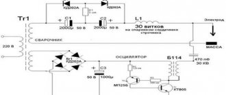
So, we've decided on this, let's move on. High voltage driver. The author chose a cheap 35W driver and an equally cheap lamp with a temperature of 6000K.
Assembling the 3S2P battery
. We install the 18650 lithium-ion cans into holders and then connect them using nickel tape.
Thick and also quite long wires come out of the ignition unit, which will interfere with us. Therefore, you will have to open the block.
Well, at the very end, all that remains is to fix the lamp in the reflector. Here you first need to focus the light beam.
To fix the lamp, a heat-resistant (up to 350°C) sealant that can withstand high temperatures is suitable. In this part of the design, measurements showed a maximum of 75°C after 30 minutes of operation.
For comparison, this is how a native incandescent lamp shines:
And this is how an inexpensive 20-watt LED lamp for car headlights shines:
And finally, this is how xenon shines:
The flashlight turned out to be truly powerful, bright and quite long-range with pleasant side illumination. Of course, there is also a drawback associated with heating, but LEDs also heat up, and they heat up quite a bit. Among the advantages, good maintainability should be noted (both the ignition unit and the lamp can be bought at almost any auto supply store, and besides, they cost pennies).
The inside, of course, is not as beautiful as the outside, but you can’t hide the wires anywhere.
The insulation copes well with such temperatures, and the battery is placed in the back of the case, where the temperature is minimal. All the insides are fixed with sealant, so nothing wobbles, everything turned out quite firmly. How to charge? The flashlight came with 2 chargers, but these chargers are no longer suitable for a new battery.
Here you need a special network charger like this.
This is a specialized charger for charging 3s lithium batteries. Such a device can be bought inexpensively in Chinese online stores.
Having walked in the evening with such a flashlight, it seems that you are not holding a flashlight in your hands, but a lightsaber that shines the same way as the headlights of rushing cars.
Thank you for attention. See you again!
Author's video:
Source
Become the author of the site, publish your own articles, descriptions of homemade products and pay for the text. Read more here.
Headlamp diagram
A popular LED flashlight design is headlamp. This lamp allows you to completely free your hands and direct the beam of light to the right place by turning your head: following your gaze. This is convenient when repairing a car, when walking through darkened areas, etc.
The circuit of such a lamp is built according to the principle:
- control circuit (responsible for switching modes);
- buffer amplifier;
- transistor switch to turn on the LED.
One of the options for such a device is when the control unit is made on a standard microcontroller (for example, ATtiny85), into which the program for controlling the emitter mode is programmed, the OPA335 operational amplifier serves as an intermediate amplifier, and an IRLR2905 field-effect transistor is used as a key.
Scheme of a pocket LED flashlight on a microcontroller.
This scheme is inexpensive and reliable, but has a technological drawback: the controller must be programmed before installation. Therefore, in mass production, a specialized FM2819 microcircuit is used as a control unit (the abbreviation 819L may be applied to the housing). This chip can turn the light emitting element on and off, and is programmed with four modes:
- maximum brightness;
- medium brightness;
- minimum brightness;
- strobe (flashing light).
Modes are switched cyclically by briefly pressing the button. A long press switches the flashlight to SOS mode. The program cannot be changed (at least, the datasheet does not mention such a possibility). The microcircuit does not require an intermediate amplifier, but very powerful LEDs cannot be connected directly to the output - there is a load limit (and there is protection against exceeding it).
Circuit of a pocket LED flashlight on a specialized chip.
Therefore, powerful elements are connected via a key. In most cases, it is a field-effect transistor that allows long-term operation with high current in the drain circuit, for example FDS9435A manufactured by Fairchild or other similar ones, which can be selected according to the parameters from the FDS9435A characteristics table.
| Structure | Maximum gate-source voltage, V | Open channel resistance | Maximum power dissipation, W | Maximum drain current in constant mode, A |
| R channel | 25 | 0.05 Ohm at 5.3 A, 10 V | 2,5 | 5,3 |
The flashlight circuit comes down to just two active elements and a string of several capacitors and resistors (plus battery cells and a matrix of LEDs, of course).
Lantern “Magic Lamp”
This is a story about converting an LED flashlight. There is an unconventional twist - warm tube analogue solutions are used! Several years ago, when LED flashlights were just starting to appear in stores, I bought a Digger LED flashlight in Okey. Large, with a pistol grip, comfortable in the hand, balanced. It had one 3 W LED, a lead battery and, according to the description, could be recharged without restrictions. This was what was needed at the dacha. As we all know, despite the 21st century and spaceships roaming the expanses of Space (C), at a distance of more than 30 km from Moscow, energy supply becomes unreliable. Energy networks cut off electricity at any opportunity - in rain, thunderstorms, heat, or just like that. Usually on Saturday and Sunday the electricity is turned off for an hour or two during the day. Probably to train the population to survive in any conditions.
Therefore, having a powerful, convenient flashlight that is always charged and ready to go is practical.
Unfortunately, lead batteries have a limited service life of about three years, especially in standby mode with constant drip recharging. My flashlight was no exception; at some point I discovered that the battery did not hold a charge, and after a short time the voltage dropped below the LED operating threshold.
You could, of course, go to any radio parts store and buy a replacement battery. But a quick study of the prices for such batteries did not arouse any enthusiasm in me. Having thought about the question, I decided that in such a flashlight it would be reasonable to use lithium batteries of the 18650 type, left over from replacing the elements in the battery of an ancient (more than 10 years old) Compaq NC6220 laptop, valuable for the presence of a hardware serial port.
Testing of six old elements showed that four elements are quite suitable, one is so-so and one is only suitable for discarding. Four 18650 cells assembled into a parallel-connected battery were the size of an old lead battery. It was surprising that the lithium cells from the old ten-year-old battery still have a capacity of about 1500 mAh from the original 2200.
If you are going to convert the flashlight to a different type of battery, which automatically means changing the control board, then you can get creative. The case is large, you can place a lot. Personally, the idea occurred to me that the correct way to control the brightness of the flashlight would be with a variable resistor. In Fig. Figure 1 shows a method for smoothly controlling the brightness of an LED flashlight using a variable resistor.
Rice. 1. A method for smoothly controlling the brightness of an LED flashlight using a variable resistor.
To replace the lead battery, I made a holder for four 18650 cells:
Rice. 2 Holder for four 18650 cells
The 18650 elements are placed on a rectangular base made of foil fiberglass, in which 1.5 mm thick grooves for contact holders made of spring bronze are cut with a Dremel. All parts are connected by soldering; a soldering iron made in USSR with a power of 200 watts was used. Solder contacts are soldered onto the holders; the thickness of the contacts is adjusted so that the 18650 are held tightly and with force. The battery pack is attached to the top of the case via two plastic insulating posts. The posts have a pin with an M3 male thread on one end and a socket with an M3 female thread on the other end. The stand is secured with a plastic nut in the hole on the base of the battery assembly, and the entire assembly is screwed with an M3 bolt through the top of the housing. The design is dismountable, allowing you to unscrew two M3 screws and remove the entire battery pack. 18650 cells can be removed from their holders without the use of tools.
The LED cannot be powered directly from a lithium source. The LED is powered by a stabilized current of 700 mA, and the voltage drop across it is about 3.7 volts. A lithium battery produces a voltage of 4.2 volts when fully charged, and 2.7 volts when discharged. The current source for the LED must be able to operate in the specified input voltage range (2.7 - 4.2 volts), providing a stable current of 700 mA in the LED. It is clear that this must be a pulse converter capable of operating in both voltage reduction and voltage boost modes. Such converters are called BUCK-BOOST and there is a certain selection of chips on the market for building converters.
Since I decided to control the brightness of the diode with a variable resistor, I need to convert the angle of rotation of the knob into a brightness control signal. To control brightness, a PWM signal is required, the duty cycle (fill factor) of which will determine the integral brightness of the LED. By smoothly changing the duty cycle, you can smoothly change the brightness. At the same time, power consumption will be reduced, prolonging the operation of the flashlight. In existing flashlights, dimming modes are activated by successive presses of a button (usually the power button, sometimes a separate button). This method seems unergonomic and inconvenient to me. I'm a fan of the old-school analog style of controlling smoothly changing parameters with a round knob that can be turned in both directions. Therefore, the optimal solution in this case seems to be a variable resistor, the handle of which can be controlled with the thumb. There are variable resistors with a switch, which can additionally be used to switch the power supply to the flashlight. If you sequentially turn on the standard button and the switch on the resistor, you will get a new quality - you can turn on the flashlight by turning the resistor knob, and the brightness will gradually increase from MOONLIGHT mode to maximum. Or you can put the resistor handle in the desired position and turn the flashlight on and off using the button on the handle, each time obtaining a preset brightness. The position of the mark on the variable resistor handle clearly determines the brightness of the flashlight and can be set before turning it on. With one button you never know in which mode the flashlight will turn on. Yes, I read the descriptions of standard flashlights and I know that they write “the flashlight must turn on in the same mode.” But all my flashlights of this type turn on random mode.
I was interested in making a converter that would be as economical as possible, would have the ability to dim the LED, and would be able to turn off when the lithium battery voltage drops below 2.7 volts. Unfortunately, life works like this: “I want it cheap, good and fast - of course, choose two out of three!” I was unable to find an inexpensive microcircuit that was both economical, could increase and decrease the voltage, and could be dimmed by a variable resistor. As a result of considering the options, I chose the NCP5030 chip. It is inexpensive (~65 rubles), has a BUCK-BOOST mode and is quite economical, i.e. conversion losses are small.
Chip parameters:
• 87% efficiency at 500 mA load current and 3.3 V input voltage • Internal synchronous rectifier • Maximum load current – 900 mA • 0.3 µA off-state current consumption • Input voltage range 2.7 – 5.5 volts • 200 mV voltage feedback to stabilize the output current • Protection against excess output voltage and overheating. • Automatic transition between BUCK and BOOST modes
The conversion frequency is fixed at 700 kHz. Such a fairly high conversion frequency, on the one hand, allows the use of inductances of small nominal values, but on the other hand, it requires careful installation and the use of the correct parts according to the manual to prevent parasitic generation.
The built-in synchronous rectifier based on field-effect transistors with low channel resistance in the open state (voltage drop about 0.1 volt) allows for a noticeable increase in efficiency compared to a rectifier even using Schottky diodes (voltage drop across a Schottky diode is 0.5 volt).
A very valuable feature of the NCP5030 microcircuit is the automatic switching between modes of lowering and increasing the input voltage. The voltage on the battery varies from 4.2 to 2.7 volts, and on the LED it should be about 3.7 volts. This means that as the battery discharges, you must first lower the input voltage and then increase it. The NCP5030 switches between buck and boost modes automatically and transparently to the user.
The connection diagram for NCP5030 is shown in Fig. 3:
Rice. 3 Connection diagram NCP5030
The disadvantage of a solution based on this chip is that it only has digital dimming control - a discrete PWM signal must be supplied to the CTRL input to control brightness with a frequency of no more than 1000 Hz. Also, the microcircuit does not have the means to monitor the battery voltage and turn off when the voltage drops below the 2.7 volt threshold.
When selecting parts, finding resistor R3 causes some difficulties. Its nominal value is 220 milliOhm or 0.22 Ohm. The voltage from this resistor (directly proportional to the current through the LED) is used by the chip to regulate the LED current. I couldn’t find such a resistor in an acceptable time and money, so I decided to make it from several parallel-connected resistors of a larger value (1 ohm or so). In addition to the low price and availability of resistors of such ratings, it is additionally possible to easily regulate the LED current by installing a different number of resistors in parallel. In my case, I ended up with three 1 ohm resistors and in parallel a 2 ohm resistor out of two 1 ohm resistors. The total resistance of these resistors (R11, R13-R16) is 0.285 ohms, which, with a feedback voltage of 200 millivolts, gives a current in the LED of 700 mA.
Rice. 4 NCP5030 Pinout
The NCP5030 chip is made in a WFDN package measuring 3 by 4 mm with 12 pins and is obviously designed for mounting on a printed circuit board. The pin spacing is 0.5 mm, the pin thickness is 0.3 mm, plus it requires connecting pin 13 "under the belly" to the general pin of the PCB for the heat sink. In Fig. Figure 4 shows the pinout of the NCP5030.
I consider it inappropriate to make printed circuit boards for single products for a number of reasons, one of which is the difficulty of finalizing the product. If some idea comes to mind, then at the stage when the printed circuit board is implemented, it is difficult to finish it. It is possible to install additional jumpers or a couple of elements, but adding a node is difficult.
Therefore, I consider the optimal technology for me to make boards from double-sided foil fiberglass by cutting tracks with a stationery knife. By taking a board of sufficient size, you can always complete a new part as new ideas arise, without touching what has already been done. The advantage of this method is that it takes minimal time to manufacture such a board; there is no need for harmful reagents such as ferric chloride or other caustic substances to etch the board. This method of “advanced prototyping” has proven its suitability - the devices made this way lived in my home for about 30 years and were taken out of service due to obsolescence and replacement with more advanced modern devices.
However, cutting a board for such a small chip is difficult or even impossible. But you can cut traces of a reasonable size, which can be done without difficulty, for example, in steps of about 1 mm, install the chip upside down and solder it under a microscope. Solder pin 13 with 0.5 mm copper wire to the common wire of the board, connect the remaining pins with 0.12 mm wire, and the power pins with a pigtail of 3-4 such wires. The result is shown in Fig. 5.
Rice. 5 Soldered NCP5030 chip
The scheme worked immediately. It only took adjusting the LED current by soldering additional 1 ohm resistors to get 700 mA.
During long-term operation (hours), the microcircuit is barely warm, the finger feels a slight warmth and that’s all. This means that the solution for heat removal by soldering copper wire is correct and ensures normal thermal operation. A thorough examination of the signals with an oscilloscope showed ideal shapes, exactly according to the manual.
To fully implement all the ideas, you need to somehow implement a PWM signal that will control the brightness of the LED and monitor the battery voltage in order to turn off the system when the voltage drops below a critical level.
An analysis of possible solutions led to the conclusion that the cheapest (35 rubles) and universal in capabilities is to use a simple ATTINY13A microcontroller. This microcontroller does not require any wiring other than a filter capacitor for power supply.
Key parameters of ATTINY13A
• Supply voltage 1.8-5.5 volts • 4 ADC channels with internal or external reference signal • Current consumption less than 1 mA • 6 programmable I/O lines (5 if you do not use the reset pin) • 2 hardware PWM channels.
The ability to program it in the Arduino environment and flash the program through Arduino also played a certain role in choosing this controller.
The capabilities of the built-in ADC are quite enough to measure the position of the variable resistor slider and measure the battery voltage. The microcontroller includes its own reference voltage source (1.1 volts), which makes it possible to measure the battery voltage. In software, you can turn on either an internal reference source (if you need to measure the battery voltage), or an external one - if you need to measure the position of the resistor slider. There are also a couple of free outputs left, which I used to control two LEDs of different colors and an analogue measuring head. Two LEDs allow you to assess the battery status at a glance: green means more than half the charge, red means less than half the charge.
To program, you need to disconnect 4 pins from the circuit and connect them to the programmer. It is inconvenient to take the microcontroller out of the crib for programming, so I installed 6 pin connectors on the board (4 signal + 1 power + 1 common). They are two pins onto which a standard jumper is placed. If the jumper is in place, the circuit operates normally. To program, you need to remove the jumpers and connect the programmer outputs to the free pins. In programming mode, the ATTINY13A is powered by the programmer.
There are enough resources on the Internet on the topic of programming ATTINY13A via the Arduino board and creating programs in the Arduino IDE. I used these sources and .
Among the subtleties, you need the boards.txt file, which correctly describes the parameters that control the processor clock and the settings of the internal divider.
Without this, the frequency of the PWM signal will be incorrect and software delays will be processed incorrectly. I also had to change the name ATTINY13 to ATTINY13A; at the beginning of the process, the programmer polls the microcontroller and throws an error if it cannot find a section with exactly the same name.
The electrical circuit diagram of the flashlight is shown in Fig. 6.
Rice. 6 Schematic diagram of the flashlight
The battery voltage is supplied to the ADC2 ATTINY13A input through a resistor divider. When measuring the battery voltage, the software turns on the internal reference source for the ADC with a voltage of 1.1 volts and therefore the maximum permissible input voltage should not exceed 1.1 volts. Based on this limitation, the ratings of the divider R1-R2 were calculated with some margin.
The voltage from the variable resistor motor is supplied to the ADC3 input and when reading this input, an external reference is used - the battery voltage. In this mode, the data from the ADC is proportional to the angle of rotation of the potentiometer slide and does not depend on the battery voltage. This data varies in the range 0-1023.
In Fig. Figure 7 shows the entire flashlight board with all the details.
Rice. 7 Entire flashlight board
Thinking about the issue of analog control of the brightness of the LED, I decided that since the human hearing and visual organs perceive the signal logarithmically, it would be correct to use a resistor with an inverse logarithmic dependence of the output signal on the angle of rotation - so that it would seem that the signal (LED brightness) changes smoothly and evenly across the entire range of rotation of the handle. When purchasing such a resistor, you must take into account the marking features of domestic and foreign resistors - domestic ones are marked as type “B”, and foreign ones – as type “A”.
Unfortunately, I was unable to purchase a small antilogarithmic (sonic) variable resistor with a switch. Therefore, I bought a small linear resistor with a switch and used a hardware hack (resistor R4 on the circuit diagram) that has long been known to radio amateurs. This method is described, for example, here.
The place for installing the resistor in the flashlight body was selected experimentally - so that it is convenient to turn it with your thumb and so that it does not interfere with other components inside (see Fig. 
Rice. 8 Location of variable resistor
When testing a flashlight with high currents (700-800 mA), poor contact appeared in the standard push-button switch. At low currents the defect did not appear, but at high currents the lamp began to blink chaotically.
I disassembled the flashlight, looked at the button, read the name, looked up the parameters on the Internet and realized that this button, in principle, is not suitable for switching such currents, since it is designed for 100 mA. I had to take the KMA 1-IV button, released in 1973 in the USSR, capable of switching current up to 3A, from the “General Staff reserves” and put it in place of the standard misunderstanding.
During testing, it turned out that in maximum power mode, the aluminum radiator on which the LED is installed heats up to about 60 degrees. Not surprisingly, the case is completely closed, thick plastic, no heat dissipation. I thought about it and drilled holes in the housing so that outside air would cool the radiator. It has become much better - now the heating is barely noticeable during long-term operation of several hours. I secured the flashlight in a vise and inserted a mercury laboratory thermometer into the hole at the top so that it touched the aluminum plate. After prolonged operation at full power (more than a couple of hours), the temperature stabilized at around 40 degrees C. In my opinion, this is quite satisfactory. In Fig. Figure 9 shows the holes in the flashlight body.
Rice. 9 Holes in the housing for cooling the LED heatsink
Testing the flashlight at full power lasted more than 8 hours before shutting down when the voltage dropped below 2.7 volts. This gives the total capacity of the four 18650 cells to approximately 6000 mAh, or 1500 mAh per cell. Not bad for 10 year old elements!
While discussing the project with my friend, a water tourist, the idea of an analogue battery charge indicator was born. Approximately the same way it was done in the first portable cassette recorders - there was a built-in dial indicator of the battery charge level and recording level. Back then, the recording level had to be set manually! Having an indication of the remaining charge before your eyes, you can decide how to spend energy: save the charge or you can turn it on full without regret.
Soon after this, I accidentally ended up in the Kvarts store on the street. Buzheninov and, looking at the display cases while waiting for his wife’s business to be completed, came across this wonderful analog indicator (Fig. 10):
Rice. 10 Analogue battery charge level indicator
Having estimated the dimensions, I decided that I could insert it into the lid. On the reverse side, the indicator rested against the board and had to be pulled out a little from the cover. The indicator is fixed with hot glue.
Rice. 11 Analog battery charge level indicator in the lid
Red and green LEDs are located above the level indicator.
To control the indicator, I used the second PWM channel in ATTINY13A. The calculation of the additional resistance and PWM parameters was carried out so that the maximum deviation of the indicator needle occurs when charging is connected, and the minimum - at a cut-off voltage of 2.7 volts. This is the digital equivalent of a “stretched scale”. It turned out fortunately that half of the battery discharge occurred right in the yellow zone of the indicator.
To control two LEDs (red and green), I had one pin left. I had to think a little :). For the solution, see the circuit diagram, elements R5 - R7 and HL1 - HL2. A minor disadvantage of this solution is the impossibility of turning off the LEDs completely, even if you switch the ATTINY13A pin to the third state - both LEDs will glow dimly.
Rice. 12 Lithium battery charging board
The last thing I attached to the flashlight was the lithium battery charging board (Fig. 12). I once bought it on die-extreme, tempted by the cheapness, but now I found a use for it. The charge is carried out with a current of the order of an ampere and takes quite a long time - up to 10 hours. However, with a capacity of about 6000 mAh and a charge current of 1A, this is approximately how it should be. During the charging process, the board lights up with a blue diode, after completion it turns green. In principle, it would be possible not to use this charger, but to disassemble the flashlight and charge the elements in a separate external charger. That’s what I planned to do at first, thinking that 6000 mAh would be enough for the whole season. But laziness, the engine of progress, won and I built in a charger. Now you just need to connect the miniUSB - USB cable from any 5V source. For charging purposes, charging from the mains with a current of 1-2 A is better, a computer port with a current of 500 mA is worse, but still acceptable. I don’t provide links to the board; searching for “1a lithium board charger” will give you a sea of links. An additional bonus is that there is no longer any need to easily disassemble the flashlight to remove the battery pack; this unit can be secured permanently.
The board is placed in the lid of the flashlight, so that when the lid is closed, the board fits into a free space in the body of the flashlight. The board is secured in place with hot glue. The MiniUSB connector is accessible from the outside.
Controlling the analog indicator was reduced to calculating the parameters of the PWM signal depending on the battery voltage.
The control program for ATTINY13A is small and I present it directly here:
Control program for ATTINY13A
void setup() { pinMode(0, OUTPUT); pinMode(1, OUTPUT); pinMode(2, OUTPUT);
/* Setting Divisor Frequency PWM on 9.6, 4.8, 1.2 MHz CPU 0x01 divisor is 1 37500, 18750, 4687 Hz 0x02 divisor is 8 4687, 2344, 586 Hz 0x03 divisor is 64 586, 293, 73 Hz 0x04 di visor is 256 146, 73, 18 Hz 0x05 divisor is 1024 36, 17, 5 Hz */
TCCR0B = TCCR0B & 0b11111000 | 0x02; // 0x02 divisor is 8 586 Hz
}
void loop(void) {
analogReference(INTERNAL); int batt=analogRead(3); delay(25); batt=analogRead(3); analogReference(EXTERNAL); int resistor=analogRead(2); delay(25); resistor=analogRead(2); int r=(resistor*32); r=r/147+33;
if (r > 255) {r=255;} //led starts to light at 13.8% PWM
if (batt > 440) { analogWrite(0, r); } else { analogWrite(0, 0); }
if(batt<560) { digitalWrite(2, HIGH); } else { digitalWrite(2, LOW); }
if(batt<440) {batt=440;} if(batt>(440+255)) {batt=440+255;}
analogWrite(1, batt-440);
}
To obtain the required frequency for dimming the LED, we had to change the timer divider to obtain a frequency of 586 Hz. In reality, the measured frequency of the PWM signal turned out to be 555 Hz, which is quite close to the calculated one, taking into account the accuracy of the built-in clock generator.
Double reading from the ADC was used because, according to some statements, the first conversion after switching the reference gives an inadequate result.
The rest of the code, in my opinion, is trivial and does not require explanation.
Tests have shown
that the assigned tasks have been completed:
The result is a flashlight with smooth brightness adjustment from moonlite to full brightness, with a battery of about 6000 mAh, which is enough for 11 hours of work at full brightness and probably for a week of work in MOONLITE mode according to calculations.
The power source is 18650 lithium cells from an old laptop battery, which have found a second life.
The LED does not overheat and is in the correct thermal mode.
Dimming at a frequency of about 550 Hz provides a more or less safe mode for the eyes.
There are both an analog battery voltage indicator and a discrete indication on two multi-colored LEDs.
The accuracy of the microcontroller's ADC is sufficient to reliably turn off the system at a critical voltage when the battery is discharged; the residual current consumption in the region of several milliamps is harmless for a battery of such capacity, even if the user does not turn off the flashlight immediately, but does so with a delay. In principle, you can change the program code so that when the battery level is critically low, the LEDs also go out completely. Then the remaining current consumption of the microcontroller of a hundred microamps will not be enough to cause significant harm to the batteries.
Built-in charging allows you to use the flashlight in standby mode with a constantly connected source, which ensures a constant 100% charge of the flashlight, which is convenient in the country during random power outages.
Project budget.
The parts cost 660 rubles for three sets, i.e. 220 RUR for one lantern. Lithium cells, etc. - for free. The analog measuring device cost 550 rubles, but it is not necessary. Of course, much more time was spent on development and manufacturing than would be required to simply replace a lead battery, but the pleasure of creativity is priceless. When purchasing the elements, I strived for unification. So, for example, if the circuit requires filter capacitors of 10-22 μF, then it makes sense to buy not just a couple of different ones, but 10 pieces of the highest value (22 μF in this case). The price for 10 pieces will be less than for single capacitors of different capacities, and increasing the capacity of the filter capacitors will only have a positive effect on the functioning of the circuit.
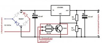
Diagram of a rechargeable flashlight with charging from a 220 network
It is more convenient and economical to power the flashlight not from batteries, but from batteries that can be charged. It is even more convenient to have such a lamp, the charge of whose elements can be renewed without removing them from the housing. Simply connect the flashlight to a single-phase 220 V network.
Scheme of a pocket LED flashlight with charging from a single-phase 220 V network.
Here the elements are added to the usual scheme:
- full-wave rectifier using diodes VD1, VD2 (can also be assembled using a bridge circuit);
- ballast capacitor for extinguishing excess voltage C1 with discharge resistance R1;
- resistor R2 to limit the battery charging current;
- chain R4VD5 to indicate connection to the power supply.
Important! Such transformerless circuits have a significant drawback. If you accidentally touch any point in the circuit, there is a risk of being energized. The use of a network step-down transformer will lead to a significant increase in weight and size characteristics.
Therefore, such a scheme is becoming less and less common. To charge batteries without removing them, use external low-output power sources (including charging from a USB-compatible device).
Modernization of lamps
Upon careful examination of the flashlight diagram from the previous section, it becomes obvious that the VD5 LED is always on when connected to a 220 V network. Its glow does not depend on the charge or even the presence of batteries. To eliminate this drawback, the indicating circuit must be included in the battery charging circuit. To do this, you need to install a resistor R5 with a power of 0.5 W so that at a current of 100 mA, about 3 V (about 30 Ohms) drops across it. The indicating circuit must be connected in parallel, observing polarity.
Scheme for finalizing the display circuit.
All changes and additions are shown with a blue line. After the modifications, the LED will light only when there is a charging current (with the power of the emitting matrix turned off!)
The simplest pocket flashlight, including a headlamp, consists of a light source with a reflector, a power button, and a disposable or reusable battery. Thanks to modern technologies, flashlights mainly use LEDs, which have a high luminous flux with low power consumption. This makes it possible to produce small portable lamps with batteries that allow charging from a 220V network. Let's look at the design of one of these flashlights in the article, which in the future will allow us to find the fault and repair it.
Content:
- LED headlamp device.
- Diagram of a headlamp with battery.
- Technical characteristics of the headlamp.
- How to charge a headlamp battery.
LED headlamp device.
We will use as an example a smartbuy rechargeable headlamp, which is assembled from Chinese-made components. Main components:
- LEDs;
- battery;
— charger for the current source.
For lighting, 12 lighting LEDs are used, placed separately from each other in reflectors. Using the switch, 2 operating modes of the lamp are set. In the first position, four LEDs located in the center light up, in the second position - the remaining eight around the circumference.
A maintenance-free lead-acid battery with a voltage of 4V and a capacity of 0.5 Ah is used as a battery.
To connect to a 220V network, a short extension cord with a plug and socket is used, as well as a plug attachment for convenience.
Diagram of a headlamp with battery.
To understand how the charger works, we will use the electrical circuit of the flashlight. Its function is to convert 220V AC to 4V DC. The charger is implemented using a voltage divider in the form of resistor R1 and a rectifier bridge VD1-VD4, assembled from silicon rectifier diodes type 1N4007. During the battery charging period, when connected to the network, due to resistor R1 (560 kOhm), the voltage drops from 220V to 9V. In addition, the voltage decrease occurs due to the pn junctions of the rectifier diodes. As a result, 7.2V is supplied to the terminals of the battery.
The battery charging voltage will depend on the quality of manufacture of R1, that is, on the correspondence of the specified resistance value to the actual value. And this affects the service life of the current source.
Since alternating current of industrial frequency 50 Hz changes direction every 0.01 sec, it flows from phase to zero along the chain: L - VD1- +GB - VD3 - R1- N. And in the opposite direction along the circuit: N - R1 - VD2 - +GB – VD4 – L. The charging current is 0.05A. The power consumption of the charger with battery is 15 W.
The HL1 LED signals the battery charging process. Connects to the “+” terminal of the diode bridge and resistor R1. A voltage of 1.7 V is applied to the indicator LED, further reduced by resistance R2 (330 Ohms).
Film capacitor C type CL21105J, with a capacity of 1 μF and a rated voltage of 400 V, is a common radio element for reducing interference.
Technical characteristics of the headlamp.
Type of LEDs: lighting LEDs.
Number of LEDs: 12 pcs.
LED switching mode: 1 - 4 LEDs, 2 - 12 LEDs.
Battery type: Lead-acid, voltage 4V, electric capacity 0.5A∙h.
Charging current: 0.05 A.
Charging power consumption: 15 W.
How to charge a headlamp battery.
To start charging the battery, connect the flashlight to the mains via an extension cord. The red LED will light up while charging. Unfortunately, the charger circuit does not provide an indication that charging is complete.
The lead-acid battery is charged with a constant charging current of 0.05 A, the recommended value of which is 0.1 of the electrical capacity of the battery 0.5 A∙h. With this method, the battery is filled with electrical energy for 6-7 hours.
It is not allowed to turn on the LEDs when charging the battery. Otherwise, the light sources will receive a voltage of 7.2 V, which is almost twice their nominal voltage. As a result, the LEDs will fail, and quite quickly.
Functionality check
If a Chinese flashlight fails, you can try to find the faulty element and replace it or repair it. The search algorithm is shown using the example of a lamp with mains charging.
Scheme for checking the performance of the lamp.
- If the lamp does not light, the indicator does not light up when you turn it on, you need to check whether 220 V is supplied to the circuit. To do this, you need to measure the alternating voltage at point 1. If there is no voltage, you need to check the power cord and connector.
- If everything is ok, the LED should be lit. If not, check its circuit, as well as the VD2 diode for a short circuit.
- Next, you need to remove the batteries and check the constant voltage at point 2 - it should be approximately equal to the voltage of the batteries. If not, check the serviceability of diodes VD1, VD2.
- If everything is ok, the batteries are probably faulty. You need to check the voltage on them.
- If this is not the case, you need to check the serviceability of the switch by ringing it with a tester in sound test mode (with the device disconnected from the network and the batteries removed!).
- If everything is fine here, the fault must be looked for in the driver or in the LED matrix.
With a little knowledge of electrical engineering, upgrading or repairing a handheld flashlight is easy. The main thing is to understand its structure.