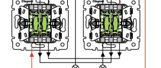
Schematic and installation electrical diagrams
In most of the technical documentation for the construction of facilities, you can find the electrical part of the project, even if the design of the electrical supply is not being carried out. Apartment lighting, installation of equipment, alarms and many other areas in construction may require you to be able to read a variety of electrical drawings. Let's look at how to do this using the example of the most understandable wiring diagram.
This is a working drawing, according to which all connections and connections of individual elements of the system are made, and they are indicated in accordance with their actual location. This document details the brands, sections, and method of laying connections.
All device locations are valid and accurate. This diagram is based on a schematic diagram and is created at the final stage of the facility's power supply project.
Office power supply project
Back
Forward
Schematic and installation electrical diagrams are very similar to each other, they are carried out according to the same GOST standards, and their main difference is that in the schematic electrical drawings the location of the elements of one device is not important; they can be indicated in different parts of the diagram. The wiring diagram is very important not only for connecting and installing devices, but also during the further operation of the equipment; it greatly facilitates troubleshooting.
Wiring diagram - block
The wiring diagrams of units with a small number of devices are carried out in the same way as the wiring diagrams of electrical cabinet panels. But for blocks it is recommended that the jumpers be mounted separately (Fig.
You should start drawing up wiring diagrams of blocks by finding ways to reduce inter-hardware connections. When installing the blocks, the possibility of soldering non-wire resistances, semiconductor diodes, triodes, and small capacitors directly onto the petals and terminals of the devices is used, as well as connecting the terminals of transformers and chokes without intermediate wiring.
| End-to-end frequency response of the PTK-4S block. |
In Fig. 1 - 194 shows the wiring diagram of the block, and in Fig. 1 - 20 - end-to-end frequency response.
The wiring diagram of the printed circuit board of the KSDV radio unit and the wiring diagrams of the IF unit and intermediate frequency transformers are shown on the color insert.
| Schematic diagram of the Estonia-stereo power supply. |
In Fig. 44 shows the schematic diagram and the color insert shows the wiring diagram of the KSDV unit.
| Tuning card for Temp-6 and Temp-7 TVs. |
In Fig. 3 - 13, 3 - 14 and 3 - 15 show the wiring diagrams of the vertical and horizontal scanning units, as well as the location of parts on the line linearity control bar.
The relative location of low-current devices on the panels and chassis of the units according to the mounting connections is determined only when drawing up the wiring diagrams of the units. This especially applies to relay units with numerous connections between devices.
On the inside of the cover of the device there should be a plate with its circuit diagram, and on the body of each unit there should be a plate with the wiring diagram of the unit.
For blocks and panels with a large number of devices of the same type, especially for relay devices, it is convenient to use installation tables. In this case, on the wiring diagram of the block (panel), the wires are not shown even as arrows. Only the numbers of the contact petals of the devices are designated (Fig. Each contact group is assigned a letter (L, V), and each petal in the group is assigned a serial number. The terminals of the relay windings are designated by Roman numerals.
In what order are the addresses composed if the diagram contains both switchboards and racks? Sequential numbering to indicate addresses should begin with the wiring diagram of the control panel unit and continue on the assemblies related to this unit. The addresses of the wiring diagram of the next block must start again from the first number and end at the resistance assemblies of this block. In the same way, you need to put down the serial numbers of the drawing sheets.
An external inspection is carried out and the soldering is thoroughly checked. The insulation resistance of the block circuits is measured and tested with increased power frequency voltage. High voltage test conditions are usually indicated on the wiring diagrams of the AVR units. The test voltage values and test conditions are given in Table. 10 - 8, compiled on the basis of the manufacturer’s instructions.
As a result of the analysis, a list of errors and recommendations for preventing them is produced. The internal communications block works out the rational connection of the elements of each board and generates a program for the operation of the assembly machine. The remaining blocks provide output to the wiring diagram, a list and addresses of output contacts, as well as a map of the location of connectors and conductors. To process data using this program when drawing up circuit diagrams of blocks containing up to 640 transistors located on 80 boards, RAM with a capacity of up to 32,000 words and a fairly extensive set of VRAM for storing regular data and program libraries are required. Carrying out all calculations for each block requires only 12 - 15 minutes. The cost of wiring diagrams compiled using a digital computer is reduced by about ten times compared to conventional manual methods. In addition, all installation errors can be virtually eliminated.
How to read a wiring diagram correctly
Reading an electrical wiring diagram accomplishes the task of determining what should be connected where and how. Getting acquainted with the drawing should begin with a list of elements, finding them in the drawing and reading the explanations for them. It is necessary to break the circuit down into simpler circuits and look at them first, and then look at the complex interaction of the circuits in the system. It is worth familiarizing yourself with the symbols and markings. Particular attention should be paid to references to other drawings, if any.
Some items on the wiring diagram may be omitted. In this case, you should refer to the schematic drawing. Sometimes connection and connection diagrams are carried out separately, and in the former, special attention is paid to the location and methods of fastening the conductors. All wires have their own individual number; this number is indicated on the wires after connection. Sometimes installation drawings indicate only pins with numbers instead of wires; this method of executing a circuit is called address-based. If changes are made to the project during installation, an as-built assembly diagram is drawn.
Below you can use the online calculator to calculate the cost of designing power supply networks:
How to read wiring diagrams and make installations based on them
Wiring diagrams are drawings that show the actual location of components both inside and outside the object shown on the diagram. Such circuits are drawn for the installation of many types of radio equipment and not only, with the help of wiring diagrams, for example, electrical cabinets are assembled. The wiring diagram is a list of radio parts, assemblies and components, but they are not connected to each other by tracks; the route is indicated on the terminals of these elements. A route is an alphanumeric designation on the diagram, indicated on the terminals of the elements, indicating which other element this circuit should be connected to. All wiring diagrams read the same, but engineers may draw them differently. In this article we will learn how to read wiring diagrams and do installation; I will give all examples with electrical cabinets.
Wiring diagrams
When installing, it is convenient to work with two circuits, the installation circuit and the electrical circuit. The wiring diagram is drawn after drawing up the circuit diagram; some points may be missed when drawing up wiring diagrams; in this case, you can refer to the electrical diagram. Let's take a small piece of the circuit diagram and see how it should be read, how to correctly indicate the route, etc., for example, there is this piece of the wiring diagram:
The diagram shows 2 relays, what type they are and what voltage is usually indicated next to the relays, or written in the electrical diagram, i.e. If the wiring diagram does not say (or maybe you forgot to write) the operating voltage of any element, open the electrical diagram, find this element there and look. In this case, we depict 2 relays: KV8 and KV9, in circles, above the element the serial number or element number is indicated. And the circles inside are, as you probably already understood, the contact pads of the relays, if in another way, then the seats, contacts. A number is also written inside the circles, and the letters - A- and - B- indicate contacts for power.
Contacts that must be connected to other elements are carried out in strips beyond the edge of the case and a route is written on the edge; in our case, one contact with route -41B- departs from element -40-, this route indicates that contact number -B- of element number -40- must be connected to contact -B- of element -41-. We can say that contacts -B- of the relays -40- and -41- are connected together. As for the route instructions on cambrics, on element -40- a wire is screwed onto contact -B- (since we have relay contacts with screw terminals) on which the cambric is put on with the inscription -41:B-, and on element -41 - another cambric with route -40:B- is put on contact -B-.
To put it simply, cambrics (or cable markers) indicate return routes with connected elements.
On some elements, for example on the same relays, some radio elements may be drawn; below in the diagram, diodes are drawn parallel to the windings of the relays:
Such elements, as a rule, in the drawings will be connected directly to the contacts WITHOUT indicating the routes - why write a route when it is already clear that the anode of the diode -VD5- is connected to contact -B- of the relay -K4-, and the cathode is connected to contact -A- of the same element. Cambrics are NOT used for the output of such elements and the route accordingly is not written. If you look more closely, in diagram 2 you will see a so-called jumper that connects contacts -A- of elements -30- and -31- (relays -K4- and -K5-) to each other. Such jumpers are usually drawn in cases where it is easier to draw a line between elements, especially if they are located next to each other, than to write a route on the diagram. If the elements were located at different ends of the wiring diagram, then drawing a long line connecting these two elements would not make sense; it would be easier to indicate the route. I think, and here it is clear that contact -A- of element -30- is connected to contact -A- of element -31-. There is also a jumper on the diagram that connects contacts -11- and -A- of element -30- to each other. The jumpers usually do not indicate the route, both on the installation diagram and when installing this section, the diagram, but I still advise beginners not to be lazy and sign the cambrics.
The installation of the circuit can be carried out with different wires, for example, shielded, power, ordinary wiring, etc. or wires with different sections. On wiring diagrams, it is usually written on the edge which wires need to be used for installation and what their cross-section is, an example is below:
Below you can see a small section of such a diagram, which indicates which wire to use to install these circuits. From the diagram it can be seen that the installation of contacts 1,2,4 of connector X13 must be carried out with a wire with a cross-section of 0.35mm2, and the connection (installation) of contacts 9,15,16 is carried out with a wire of 0.75mm2, etc. By the way, grounding installation is carried out with a yellow-green wire, as is customary.
Typically, most elements on wiring diagrams are easy to read and understand, many elements (resistors, capacitors, diodes, light bulbs...) are designated in a standard way.
But often, on the assembly line they draw elements, after looking at which you don’t immediately understand what they are, in such cases we look at the serial number of the element and go look for it on the circuit diagram. Here, for example, is one of the options for designating screw terminal blocks - you must admit, you won’t immediately understand what it is.
Below is the designation on the wiring diagram of a three-phase transformer; the fact that this is possibly a transformer can be guessed by the inscriptions A, B, C (phases).
This is how a three-pole circuit breaker can be designated
By the way, they can be very different, there are circuit breakers for 10-20 amperes, and there are for high currents (1000A or more) with a magnetic drive, which electrically switches the circuit breaker, when triggered there is a strong crackling noise. In general, difficulties arise only at first; if you get a job at some enterprise, consult with the employees or the engineer, the one who drew the installation.
Installation
The installer usually connects the parts in the cabinet body with wires. But some people’s responsibilities also include arranging elements inside the cabinet. We will only consider connecting the elements to each other with wires. Before you begin installation, figure out in your head how you will route the wiring harnesses inside the cabinet. Try not to lay a lot of bundles; if the wiring diagram contains elements that are connected to each other by a shielded wire, then the shielded wires must be laid separately, and the screens themselves must be connected to a common wire or ground. It is advisable to fasten the power wires after completing the main installation. Wires for installation are usually provided in coils or reels; they should be unwound carefully and there is no need to cut off several ends; for convenience, they are placed in special stands for easy unwinding; and also, do not throw away the plate that comes with the wire; the plate indicates the cross-section of the wire and some other parameters, if you lose it, next time it will be difficult to determine the parameters of the wire. The cambrics are needed to indicate the route, which are then placed on the ends of the wires. Indicating routes is necessary so as not to get confused in the wires yourself; there is no need to call them every time in case you forget which wire goes where. In addition, this makes troubleshooting and repairing the device easier.
Photo from the archive, this is what my workplace looked like:
Required Tools
Before starting installation, prepare the following tools:
- Wire stripping tools are designed for convenient removal of insulation from wires. Ordinary wire cutters can damage the wires.
- A set of casings for the types of wires used; do not put too thick and wide cambrics on thin wires. It is not recommended to use heat-shrinkable tubes instead of cambrics (PVC tubes), because they can shrink when exposed to strong heat.
Also, if your budget allows, you can use cable markers.
- A marker for writing routes on cambrics, preferably with a thin rod and permanent.
- Liquid flux, rosin, solder, soldering acid or oxide may be useful for soldering oxidized leads of radio elements, petals, etc., soldering iron 25-40 watts.
- Self-adhesive pads for attaching harnesses to cabinet walls.
- Ties or clamps for tying wires. In some cases, special plastic cases or channels are used - inside which the wires are laid.
Of course, something else may come in handy, but as a rule this is enough. Most importantly, start working in a good and cheerful mood to avoid mistakes - electronics don’t like jokes.
Before starting installation, carefully study the diagram; installation should begin from the area where the most elements are located; you should also pay attention to where the wires go. If a group of wires goes from one section to another section, you need to start from this place. If there are devices and buttons with regulators on the cabinet door, then installation begins with the door; a loop is made from the resulting wiring harness from the door to the cabinet body so that the door opens and closes normally.
Installation can be performed with different wires; the wiring diagram always indicates which wire should be used for a given section of the circuit; it is not recommended to do installation with a wire of a smaller cross-section than indicated in the wiring diagram, because a wire with a smaller cross-section may not withstand the required currents and may melt or become exposed. Never remove more insulation from a wire than is necessary; firstly, it is not beautiful, and secondly, it may accidentally short out if the wires are located next to each other. If the wires are attached, say, to relays or to terminal blocks using screws, estimate how deep the wire can go under the screw - that’s how much and remove the insulation. The terminals of wires from which the insulation has been removed and which are attached to elements in the cabinet must always be tinned! As soon as one end of the wire has been stripped and tinned, a cambric is taken, a route is written on it, after which it is put on the wire, and the wire itself must be soldered or screwed to the element. A cambric is also placed on the other end of the wire indicating the return route, then the end of the wire is tied into a knot and the wire can be thrown; we do not need this end of the wire yet. At the first stage of installation, cambrics are put on all other ends of the wires indicating the routes, the ends are tied in a knot so that the casing does not fly out and the wire is thrown. When you finish attaching the ends of the wires in a certain area, you will end up with a small braid of wires. Then this pigtail is carefully assembled and laid along the body (along the wall) of the cabinet, the wires are laid to the element where they should go according to the wiring diagram, i.e. from one element to another. As the laying progresses, the harness can branch and go to another element.
In the end, a bundle of wires with dressed cambrics at the ends should form. The figure above shows a bundle of wires near the terminal blocks; the wires are cut to the required length, the insulation is removed from them, tinned, and attached to the terminal blocks. And so on with all the wires that, according to the wiring diagram, should go to this element.
Of course, with the installation of simple household devices, such as power supplies or AF amplifiers, everything is much simpler. Typically, when connecting nodes or boards to each other with wires, you can specify power buses, input or output, plus or minus power, voltage, and so on as routes.
As soon as the main installation is completed, you can begin installing the power circuits; cambrics are put on the power wires in the same way and the route is written in the same way. More often, power wires are used for supply circuits and on cambrics, as a rule, only the phase is indicated.
After the installation is completely completed, they begin to test the circuits. DO NOT TURN ON THE DEVICE WITHOUT PRELIMINARY CHECKING AND CALLING! For dialing, it is convenient to use a multimeter with a tweeter. For example, in the diagram below, if we touch one probe of the multimeter to the contact of the resistor -4:1-, and the other probe to the contact of the light bulb indicating the route -23:R12- - the multimeter should beep, if it turns out that there is no contact, then the multimeter naturally will be silent.
In this case, you need to look for an error; perhaps you screwed one of the ends of the wire to another element, or it is quite possible that there is simply no mechanical contact, especially if the clamps are screw. Finding errors is a rather labor-intensive process; it is better to do everything correctly and without errors from the beginning; after installing a section of the chain, always recheck the chain. If after checking no errors were found, then you can slowly start launching. First, as a rule, they simply supply power, while the machines are turned off and the boards can be removed from the device, thus once again checking the correct installation and whether there is a short circuit anywhere. Afterwards, you can check the indication and starters by forced switching on, as well as other auxiliary elements of the circuit. Of course, different devices are configured and adjusted in different ways; it is impossible to give exact recommendations here. In general, my responsibilities only included installation of the circuit, and the configuration was already carried out by another specialist. During the first start-up of the device, touching the body and elements is strictly prohibited! Always turn off the power COMPLETELY before accessing the device.

