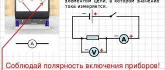
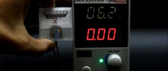
The approximate price is 3.5 USD. Let's look at the diagram for connecting a Chinese voltmeter-ampmeter of the first model to an adjustable power supply.
Modernization and repair After converting the ATX power supply into a laboratory one, I wanted to equip it with an ampere-voltmeter. Apply the minus of the external source to the common wire of the circuit. It is not clear why the Chinese decided to save on a couple of cheap parts. Chinese ampere-voltmeter - connection errors Connection diagram When the current through the device was 7 amperes, the shunt on the board, made in the form of a U-shaped jumper, noticeably heated up.
The order arrived, everything was fine with the blocks, there were no mechanical damages, but there was no passport or instructions describing how to connect the device. If everything has been connected correctly, two scales should light up on the display.
This will also appeal to those who work on expensive equipment, the operation of which can be adversely affected by regular drops in network voltage.
Perhaps this is a microcontroller of wide application, but I have not seen one like this in a SOIC package with ground on the 1st pin and power on the 1st pin. Their cost is clearly an order of magnitude lower than other components, the same ad, for example.
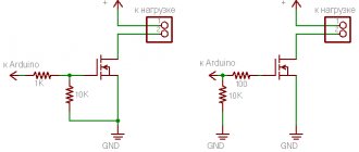
To remake, you will need initial reverse engineering skills to make sure that the circuit is the same, soldering of small parts and knowledge of Ohm's law: Scheme before rework: Scheme after: Cut tracks are indicated in red. VOLTMETER-AMMETER TEST, CALIBRATION, CONNECTION DIAGRAM. ALIEXPRESS
Join the conversation
Given the wide range of modern voltammeters, you may encounter problems connecting them. We connect the resistor to the voltmeter-ammeter Second. But let's look at the colors of the wires.
Not everyone will immediately understand which wire needs to be connected where, and the instructions are usually only in Chinese.
Most devices can be adjusted using built-in resistors.
The fan speed will also decrease, but at low voltage the power supply heatsinks will be a little warm and nothing bad will happen.
Diagram for connecting a voltmeter-ampmeter to an adjustable power supply. At the bottom of the circuit, the fan and the Chinese voltmeter-ampmeter are connected through an LCV voltage stabilizer to the output of the diode bridge in parallel with capacitor C1.
It was not immediately and at the right time that it became clear that its power input was galvanically connected to the minus input of the shunt. Chinese voltmeter - ammeter after modification Here it turned out that the wirewound resistor, instead of the recommended resistance of 0.08 Ohm, has 0.8 Ohm.
It is more expensive than previous models, but also has a higher upper limit of measurements in V. It was possible, of course, to install another duty station and power the indicator from it, but it seemed to me too bold and I decided to hack the indicator itself. How to connect a Chinese ammeter voltmeter
Recommended Posts
Since the operation of measuring instruments is affected not only by their own faults, but also by faults in the connected devices, sometimes it is necessary to make adjustments.
The switching was performed when the power supply to the load was turned off.
About the shunt.
Having bought a couple of these ampere-voltmeters, one immediately burned out at 26 volts. No spam, only useful ideas! Connection diagram of a voltmeter-ampmeter and a fan to a charger from a computer power supply. Download a diagram of connecting a voltmeter-ampmeter and a fan to a charger. Everything is clear with a charger from a computer power supply.
In other cases, the display will only show the voltage drop. On the freed contact, on the side of the trimmer, a wire of the desired length is soldered for testing, conveniently mm and preferably red. Solder the SMD resistor Third. Equipped with tuning resistors. For clarity, I recorded the result of my efforts on a video.
Chinese ampere-voltmeter connection diagram
At 10 amps it is already hot. Therefore, I propose to consider the connection diagram of a classic pointer voltmeter and ammeter. By rotating them, you can change the zero values. Circuit YB27VA The device, of course, has its own measurement errors; to adjust the current and voltage readings to those close to reality, two trimming resistors are installed on the board, respectively, one for current and the other for voltage.
In other cases, the display will only show the voltage drop. It is also desirable that the device have a shunt to finalize the connection process. To avoid additional costs, before purchasing an ammeter, always check with the seller about the presence of a shunt inside the device. If you recalculate the divider, then the “preadometer” can be used not only as a voltmeter - for example, you can display current, temperature, etc. It is equipped with tuning resistors.
Lately I have been literally inundated with questions about how to connect, where to connect. I got µV at the input of the op-amp. How to connect a WR device When designing chargers for batteries and various power supplies, many radio amateurs use ready-made voltmeters-ampmeters made in China, which can be easily bought on the Internet, for example, on the Aliexpress website. How to connect a voltmeter ammeter