Connection diagrams
To carry out measurements, an ammeter is connected in series to the electrical circuit with the section where it is necessary to measure the current. To increase the measurement limits, the ammeter is connected through a shunt or transformer.
The most common is the ammeter circuit, where the moving needle rotates through an angle of inclination that is proportional to the magnitude of the force being measured.
Voltage measurement. Voltmeter.
A device designed to measure voltage is called a voltmeter . And, unlike an ammeter, it is connected to the circuit parallel to the section of the circuit at which the voltage needs to be determined. And, again, in contrast to an ideal ammeter, which has zero resistance, the resistance of an ideal voltmeter should be equal to infinity. Let's figure out what this is connected with:
If there were no voltmeter in the circuit, the current through the resistors would be the same and determined by Ohm’s Law as follows:
So, the current value would be 1 A, and accordingly the voltage on resistor 2 would be equal to 20 V. This is all clear, but now we want to measure this voltage with a voltmeter and turn it on in parallel with R_2. If the resistance of the voltmeter were infinitely large, then no current would simply flow through it (I_B = 0), and the device would not have any effect on the original circuit. But since r_B has a finite value and is not equal to infinity, current will flow through the voltmeter. In this regard, the voltage across resistor R_2 will no longer be the same as it would have been in the absence of a measuring device. That is why the ideal voltmeter would be one through which no current would pass.
As with the ammeter, there is a special method that allows you to increase the voltage measurement limits of the voltmeter. To do this, it is necessary to connect an additional resistance in series with the device, the value of which is determined by the formula:
This will cause the voltmeter to be n times less than the measured voltage. As usual, let's look at a small practical example:
Here we added additional resistance R_3 to the circuit. Our task is to measure the voltage across the resistor R_2:\medspace U_2 = R_2\medspace I_2. Let's determine what result the voltmeter will give us when turned on in this way:
Let's substitute the expression for calculating the resistance of the additional resistor into this formula:
Thus: U_B = \frac. That is, the voltmeter readings will be n times less than the voltage value that we measured. So, using this method, it is possible to increase the measurement limits of the voltmeter!
At the end of the article, a few words about measuring resistance and power.
To solve both problems, it is possible to use an ammeter and a voltmeter together. In previous articles (about power and resistance), we dwelt in detail on the concepts of resistance and power and their relationship with voltage and resistance, thus, knowing the current and voltage of an electrical circuit, we can calculate the parameter we need. Well, in addition, there are special devices that allow you to measure the resistance of a section of a circuit - an ohmmeter - and power - a wattmeter.
In general, we’ll probably finish here for today, stay tuned and visit our website! See you soon!
Source
Types of ammeters
According to their action, all ammeters are divided into electromagnetic, magnetoelectric, thermal, electrodynamic, detector, induction, photo- and thermoelectric. All of them are designed to measure the strength of direct or alternating current. Among them, the most sensitive and accurate are electrodynamic and magnetoelectric ammeters.
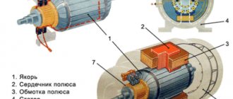
During operation of a magnetoelectric ammeter, a torque is created through the interaction between the field in a permanent magnet and the current passing through the frame winding. The arrow moving along the scale is connected to this frame. The arrow is rotated by an angle proportional to the current strength.
Ammeter connection
Now we’ve reached the main section of the article. When connecting an ammeter, perhaps only one question may arise: should the device be connected in parallel or in series to the circuit under test? The answer is also the same: CONSISTENTLY. In this case, the connection can be direct or indirect.
In the case of a direct connection, the ammeter is connected to the circuit between the power source and the electrical appliance. With an indirect connection, connection to the circuit occurs with a shunt or through a transformer. If the shunt increases the resistance of the network, then the transformer converts the current with large values to values that can be measured with an ammeter.
For your information. The significant difference between connecting a voltmeter and an ammeter is that the voltmeter is connected in parallel. Because of this, professionals say that a voltage meter is connected to the circuit, and a current meter is connected to the circuit.
When connecting an ammeter, you need to consider several important points:
- the current measured in the circuit should not exceed the maximum permissible for this device;
- When connected to a circuit, polarity must be observed.
During measurements, it is necessary to ensure that there is no vibration in the place where the ammeter is installed. The procedure for connecting the device is as follows:
- The incoming and outgoing contacts and their polarity are determined. The positive contact is colored red, the negative contact is black. On some models there may be another contact, mostly green. This is grounding.
- Depending on the circuit with which current (direct or alternating) measurements will be taken, the device switch is switched to the “AC” or “DC” position. The first symbols indicate a circuit with alternating current, the second - with direct current.
- Anywhere between the power source and the energy-consuming device, one wire of the electrical circuit is broken.
- The ammeter is connected in series to the circuit.
After the movement of the arrow, or the change of numbers on the display, stops, current readings are taken.
Varieties
The described measuring device has come a long way and many upgrades. Today, there are analog and digital types of these devices. There are also: magnetoelectric, electromagnetic, electrodynamic, ferrodynamic types of ammeters. Each type has its own characteristics of the device and its operation. Each type will be described in more detail below.
Magnetoelectric device
A special feature of these devices is a magnetic coil, which moves when exposed to electrical voltage.
All such devices are used to measure direct current. The advantage is very high sensitivity and measurement accuracy.
Electromagnetic
The device does not have a rotating coil in its design.
The change in the angle of the hand on the dial occurs due to the magnetic field acting on the cores of the coils. Similar ammeters are of a universal type. With their help you can measure the strength of direct and alternating current. The main disadvantage is the presence of error.
Electrodynamic
The device is similar in design to a magnetoelectric one. The main difference is the presence of moving and fixed coils.
When connected, the magnetic fields of the two elements influence each other, which leads to a change in the position of the arrow. The device is quite accurate. The only drawback is that its operation can be affected by extraneous magnetic fields.
Ferrodynamic
This measuring device is considered the most accurate. The ammeter device includes a ferrite wire, a metal core and a coil.
The device operates on the principle of coil rotation due to the formation of a magnetic field. The main feature is complete independence from the influence of extraneous magnetic fields. Has high sensitivity.
Electronic
With the development of electronics, ammeters began to be produced in digital variations. The two most famous are a simple household multimeter and a clamp meter tester.
The main advantage of such devices is the simplicity and versatility of current measurement. They are not susceptible to external magnetic fields, are not afraid of shocks, minor damage and shaking. Close to an ideal ammeter.
For information! An ideal ammeter is an ammeter with zero self-resistance.
All the devices described are used to this day in instrument making, laboratories, industry and by individual enthusiasts.
Types of ammeters
Based on the type of reading device, ammeters are divided into devices with:
- with pointer indicator
- with light indicator;
- with a writing device;
- electronic devices.
According to the principle of operation, ammeters are divided
- Electromagnetic – designed for use in direct and alternating current circuits. Typically used in conventional AC electrical installations with a frequency of 50 Hz.
- Magnetoelectric - designed to record the current strength of low values of direct current. They have a magnetoelectric measuring device and a scale with graduated divisions.
- Thermoelectric devices are designed to measure current in high-frequency circuits. Such devices include a magnetoelectric mechanism made in the form of a conductor to which a thermocouple is welded.
Let's look at several ammeters from different manufacturers and different types:
Ammeters Am-2 DigiTOP
- Number of inputs 1
- Measured alternating current 1...50 A
- Measurement error 1%
- Indication resolution 0.1 A
- supply voltage -100…-400 V, 50 (+1) Hz Overall dimensions 90x51x64 mm
Laboratory ammeter E537
This device (ammeter E537) is intended for accurate measurement of current in AC and DC circuits.
Accuracy class 0.5.
Measuring ranges 0.5 / 1 A;
Technical characteristics of ammeter E537
- Measuring range end value 0.5 A/1 A
- Accuracy class 0.5
- Normal frequency range (Hz) 45 - 100 Hz
- Operating frequency range (Hz) 100 - 1500 Hz
- Overall dimensions 140 x 195 x 105 mm
Ammeter CA3020
The basic model digital ammeter device is available in several standard modifications depending on the basic value of the measured current parameters. When ordering this model of digital ammeter, you must state what basic current parameter you will have to work with: 1 A, 2 A or 5 A.
Basic parameters of the measured current, In-1 Ampere (CA3020-1), 2 Ampere (CA3020-2) or 5 Ampere (CA3020-5);
- The limits of measured currents are from 0.01 In to 1.5 In;
- Frequency range for measured currents from 45 to 850 Hertz;
- The limits of the basic permissible existing error are ±0.2% of the optimal value of the parameters of the measured current strength;
- Power supply voltage - alternating current network with voltage (85-260) Volts and frequency (47-65) Hertz or constant voltage (120 - 300) Volts;
- The power consumption of the device is no more than 4 VA;
- Dimensions 144x72x190 mm;
- Weight no more than 0.55 kg;
- The power consumed by the measuring circuit of series 3020 ammeters does not exceed: for CA3020-1 – 0.12 VA; for CA3020-2 – 0.25 VA; for CA3020-5 – 0.6 VA.
Source
How to connect an ammeter
The ammeter must be connected in strict sequence - it is located between the power source and the load. To carry out correct measurements, you must clearly know the type of voltage in the power source - direct or alternating current. It is necessary to use only the device appropriate for the specific type of current.
Let us explain in detail how you need to connect the ammeter in order to obtain accurate and correct current readings:
- you need to select the required shunt, the maximum current of which is lower than the current that needs to be measured;
- then the ammeter is connected to the shunts with special nuts located on the ammeter itself;
- the ammeter is connected only after the device being measured is de-energized by breaking the electrical circuit;
- connect the ammeter to the circuit with the shunt;
- connect the elements correctly to ensure strict polarity for correct display of data;
- connect the power supply, after which you can read the results on the ammeter.
As a precaution, we note that under no circumstances should the ammeter be plugged into an outlet without any load. Since the device has a low input resistance, it will simply burn out when connected without a load.
The areas of application of ammeters include large industrial enterprises for the generation and distribution of electricity, as well as construction, automotive industry, and science. They are also used in the domestic sphere among car owners to carry out independent measurements of automotive devices.
What are clamp meters used for?
What is a phase-zero loop in simple terms - measurement technique
Current transformers: device, principle of operation and types
What is an electromagnetic relay, their types and operating principle
Why do you need a magnetic starter and how to connect it
Source