Determination of direct and alternating current
For direct current, no special circuits are required - there is a milliammeter, a powerful shunt with a resistance of hundredths and thousandths of an Ohm. They are connected in parallel with each other - and the entire installation is placed in an open circuit. For alternating current, a method with a current transformer connected according to the above-described circuit is required. To prevent the needle from oscillating around zero on the scale with a frequency of 50 hertz or more, a diode rectifier is used. This is one diode or diode bridge. The voltage rating of the diode must be high enough. This way you will avoid electrical breakdown and subsequent failure of the device.
How to choose a transformer
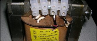
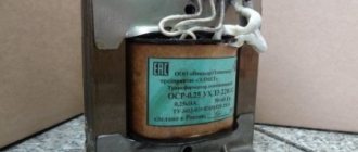
When choosing a converter, you must always take into account the load created by current consumers. Their simultaneous inclusion in the network increases the power several times, which leads to heating of the power supplies. The main characteristics are always written on the nameplate, so the voltage rating required to provide electricity is calculated using the formula I1+I2+…In, where I is the current consumption of the electrical appliance.
It is also necessary to take into account the accuracy class of the object, which will allow accurate accounting of energy consumption.
BY42A connection diagram
Signal connection diagram via relay
Setting up a digital voltmeter and ammeter In general, it is not at all difficult. It was not immediately and at the right time that it became clear that its power input was galvanically connected to the minus input of the shunt. First, without connecting the load, by adjusting resistor R5 we set its readings to zero. The composite resistor turned out to be exactly as much as needed due to the error of one of them: As a result, it now measures, starting from 50mA, up to 50A with a minimum step of about 20mA, 0 also shows. The design and quality of the voltmeters considered are unlikely to be suitable for beautiful tuning. Digital voltmeter circuit. When transmitting high voltage, less current is required for the same power. According to accuracy classes, shunts are divided into: 0.02, 0.05, 0.1, 0.2 and 0.5 - this is the permissible error in fractions of a percent. An AC voltmeter shows the actual voltage value. For this method you will need: any 4 or 5-pin automotive relay, for example, I got µV at the input of the op-amp. The voltmeter is assembled on an STM8 microcontroller. Otherwise, the pointer will point in the opposite direction to the correct direction. Also, in addition to the standard circuit, we will describe how to connect a voltammeter to a charger. How to connect a voltammeter to a charger - a selection of circuits. We have selected the 4 most common voltammeters that craftsmen use in their devices. Installing a voltmeter on a VAZ 2106 part 2
Recalibration of the device
Life hack: how to check current leakage in a car with a multimeter
A new calibration of the updated dial ammeter for the new shunt must be done as follows.
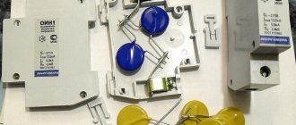
- Remove the front part of the housing (the viewing window of the device) along with the glass.
- Connect one of the light bulbs of a known value in series with the ammeter to the battery or AC power adapter. Thus, incandescent light bulbs indicate the current in amperes and voltage in volts. If you connect an LED panel or headlight, which, for example, indicates a voltage of 12 V and a power of 24 W, your operating current will be 2 A (power divided by the voltage of the power source).
- Mark at what angle the arrow of the device has deviated with a dot with a number (in this case it is 2).
- The ideal option is to turn on identical light bulbs or headlights in parallel with each other, increasing their number by one each time. This way you can “mark” the entire ammeter scale. This method is good for alternating current - the ammeter scale is nonlinear due to the influence of the frequency of the current and the drop in part of the voltage across the diodes. Marking “by eye” or using a protractor (or using an existing “ruler” of the device), as is often done with direct current, will not work. It's better to play it safe and do it more accurately.
- Having completed the markings, assemble the device and check whether the shunt is securely fastened and whether the electrical contact between it and the ammeter is good. If the dimensions of the ammeter allow, the shunt is often filled with epoxy glue, and then the resulting element (in the form of a bar) is glued to the back wall of the measuring head.
Recommended Posts
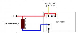
Here, no matter how you count, according to the formulas, you still have to adjust. This figure shows a wiring diagram for a voltmeter and an ammeter with a built-in current measuring shunt. After such modifications, I assembled a dsn-vc voltammeter. Separately, I would like to explain how to connect an amperevoltmeter. If the source of the measured voltage operates in the range from 4.5 to 30 Volts, then the connection diagram looks like this: 2. The devices on the board have SMD trimming resistors with the help of which it is possible to correct the readings of the voltmeter and ammeter. Once power is supplied to the circuit, the indicator will light up. When connecting the device to a DC network, the polarity of the connection is shown on the display. Each shunt has a marking indicating what current it is designed for. To move or completely turn off the point, you need to unsolder the R13 10 kOhm CHIP resistor, which is located next to the transistor, and instead solder a regular 10 kOhm resistor 0. If the source of the measured voltage operates in the range 0 -4.5 V or above 30 Volts, then up to 4 .5 Volts, the ampere-voltmeter will not start, and at a voltage of more than 30 Volts it will simply fail, to avoid which you should use the following diagram: About the wires from the kit: - the wires of the three-pin connector are thin and made of 26AWG wire - thicker ones are not needed here. In this article we will talk about a fairly cheap, but very common Chinese voltammeter marked dsn-vc Correct connection of the voltammeter
How to connect an ammeter to an AC or DC circuit
Before you figure out how to connect an ammeter, you need to know that the device must have a small resistance. This is necessary to reduce the voltage for this measuring device. Ideally, the device itself should have a zero value, but this is impossible to do in practice.
The ammeter is connected to the circuit only in series, depending on the voltmeter, which has a parallel connection. If you do everything in parallel, the current will pass along a short-circuited path, which will damage the device itself. The article will explain how to properly connect this measuring device, and this will also be shown in two videos and one laboratory work on electrical engineering.