Purpose [edit | edit code]
When connecting the windings of a generator and a power receiver in a star configuration, the phase voltage depends on the load connected to each phase. If, for example, a three-phase motor is connected, the load will be symmetrical and the voltage between the neutral points of the generator and the motor will be zero. However, if a different load is connected to each phase, a so-called neutral bias voltage
, which will cause load voltage unbalance.
In practice, this can lead to the fact that some consumers will have low voltage, and some will have high voltage. Low voltage leads to incorrect operation of connected electrical installations, and high voltage can, in addition, lead to damage to electrical equipment or a fire
. Connecting the neutral points of the generator and the power receiver with a neutral wire allows you to reduce the neutral bias voltage to almost zero and equalize the phase voltages at the power receiver. A small voltage will be due only to the resistance of the neutral wire.
Networks with resonantly grounded neutral. Setting up the DGR. DGR designs
⇐ PreviousPage 3 of 12Next ⇒
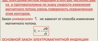
Because in networks with compensated neutrals, during single-phase ground faults, the voltages of two undamaged phases relative to the ground increase by Ö3 times; in their basic properties, these networks are similar to networks with ungrounded neutrals.
To reduce the ground fault current, grounding through arc suppression reactors (ARS) is used. In normal operation, the current through the reactor is practically zero. When one phase is completely grounded, the DGR is under phase voltage and, along with the capacitive current IC, the inductive reactor current IL also flows through the ground fault (Fig. 1.18). Since inductive and capacitive currents differ in phase by an angle of 180°, at the point of a ground fault they cancel each other out. If IC = IL (resonance), then no current will flow through the ground fault, an arc does not occur at the fault site, and the dangerous consequences associated with it are eliminated.
Selecting the settings for arc suppression reactors. When IL =IC, the capacitive component of the current at the point of the ground fault is completely compensated by the inductive current of the reactor - current resonance occurs. Arc suppression reactors usually have a resonant setting, which makes it easier to extinguish the arc. Deviation from the resonant tuning is called compensation detuning. In practice, tuning with overcompensation (IL>IC) is allowed if the degree of detuning does not exceed 5%. Tuning with undercompensation (ILC) can be used in cable and overhead networks if any emergency asymmetries of phase capacitances do not lead to the appearance of a neutral bias voltage exceeding 0.7 UF. With resonant tuning, the circuit current is minimal, and, as experience shows, overvoltages in the network do not exceed 2.7 UF. When operating overhead networks, they often deviate from the resonant tuning in order to eliminate distortions of phase voltages on substation buses, which are mistakenly mistaken by personnel for incomplete ground faults.
DGRs must be installed at central supply substations connected by a compensated network by at least three lines. When compensating generator voltage networks, reactors are usually located near generators. When connecting the DGR to the neutral of one of two generators operating on common prefabricated spikes, the reactor connection circuit must pass through the window of the core of the zero-sequence current transformer, which is necessary to ensure the correct operation of the generator’s protection against ground faults.
In networks with a resonantly grounded neutral, temporary operation with a phase closed to ground is allowed until it is possible to make the necessary switching to separate the damaged section. In this case, the permissible continuous operation time of the reactor should also be taken into account. The presence of arc suppression reactors is especially valuable during short-term ground faults, since in this case the arc at the fault point goes out and the line does not turn off.
The most common are RZDSOM type reactors with a power of up to 1520 kVA and a voltage of up to 35 kV with a control range of 1:2. The windings of these reactors are located on a composite magnetic core with alternating air gaps and have taps to regulate the compensation current. The reactors are oil cooled.
| Rice. 1.19. Design of arc suppression reactors: a - RZDSOM type; b - RZDPOM type |
More accurately, smoothly and automatically, it is possible to adjust the compensation in RZDPOM reactors, the inductance of which is changed by changing the non-magnetic gap in the core or by biasing the magnetic core steel from a direct current source.
Question 9
Selection of DGR
The total power of the DGR for networks is determined from the expression:
n – coefficient taking into account the development of the network (approximately n=1.25); IC – total ground fault current, A.
Based on the calculated Q value, reactors with the required rated power are selected in the catalog. It is necessary to take into account that the adjustable range of the reactors must be sufficient to ensure more complete compensation of the capacitive current in the event of probable changes in the network diagram (for example, when disconnecting lines, etc.).
When connecting DGRs through special transformers and auxiliary transformers, the power of which is commensurate with the power of the reactors, it is necessary to take into account their mutual influence. First of all, this influence affects the reduction of the actual compensation current compared to the nominal one due to the presence of the resistance of the transformer windings connected in series with the reactor :
Inom.r. - rated current of the arc suppression reactor; And
k% is the short-circuit voltage of the transformer; S – rated power of the transformer.
The limiting effect of the transformer windings is especially pronounced when using a star-star winding connection circuit, since with single-phase ground faults their inductive reactance is approximately 10 times greater than with phase-to-phase short circuits. For this reason, transformers with a star-delta winding connection circuit are preferable for connecting reactors. In turn, the presence of a DGR in the transformer neutral causes an additional load on its windings during single-phase ground faults, which leads to increased heating. This must be taken into account when using transformers with a load on the low voltage side (auxiliary transformers of power plants and substations) to connect the reactor. The permissible power of the reactor connected to the loaded transformer is determined from the expression:
Smax
– maximum load power.
Taking into account the overload of the transformer, permissible for the duration of operation of the network with a grounded phase and determined by the overload capacity coefficient kper, the permissible power of the reactor connected to this transformer:
When connecting the reactor to a special unloaded transformer, it is necessary to meet the condition
If the transformer overload is acceptable, the condition takes the form:
⇐ Previous3Next ⇒
Recommended pages:
Neutral in power lines [edit | edit code]
Different types of neutrals are used in power lines of different classes. This is due to the intended purpose and various equipment for protecting the line from short circuits and leaks. The neutral can be solidly grounded, insulated and effectively grounded.
Solidly grounded neutral [edit | edit code]
It is used in lines with voltages from 0.4 kV to 35 kV, with a short power line length and a large number of consumer connection points. The consumer receives 3 phases and zero, the single-phase load is connected between the phase and the neutral wire (neutral). The neutral wire of the generator is also grounded.
Isolated neutral [edit | edit code]
It is used in lines with voltages above 2 kV to 35 kV; such lines have an average length and a relatively small number of consumer connection points, which are usually transformer substations in residential areas and powerful machines in factories. In 50 kV lines, both isolated and effectively grounded neutral can be used.
Effectively grounded neutral [ edit | edit code]
It is used on long lines with voltages from 110 kV to 220 kV (clause 1.2.16 PUE) The operation of electrical networks with a voltage of 110 kV can be provided with either a solidly grounded or an effectively grounded neutral. Electrical networks with voltages of 220 kV and higher must operate only with a solidly grounded neutral.
Electric power industry is a complex industrial complex that consists of many components. In order for each element to work correctly and perform its assigned tasks, an accurate knowledge and understanding of the physical processes that occur in power equipment is necessary. Some of them are easy to explain, so we suggest you get acquainted with the concept of “neutral”.
Three-phase networks with effectively grounded neutrals
In networks of 110 kV and above, the determining factor in the choice of neutral grounding method is the cost of insulation. Here, effective neutral grounding is used, in which during single-phase faults the voltage on the undamaged phases relative to the ground is approximately 0.8 phase-to-phase voltage in normal operation. This is the main advantage of this method of neutral grounding.
Fig.6. Three-phase network with effectively grounded neutral
However, the neutral mode under consideration also has a number of disadvantages. Thus, when one phase is short-circuited to ground, a short-circuited circuit is formed through the ground and the neutral of a source with low resistance, to which the phase EMF is applied (Fig. 6). A short circuit mode occurs, accompanied by the flow of large currents. To avoid equipment damage, prolonged flow of high currents is unacceptable, therefore short circuits are quickly switched off by relay protection. True, a significant part of single-phase faults in electrical networks with voltages of 110 kV and higher are self-repairing, i.e. disappearing after the tension is removed. In such cases, automatic reclosing devices (ARDs) are effective, which, acting after the operation of relay protection devices, restore power to consumers in a minimum time.
The second disadvantage is the significant increase in the cost of the grounding loop installed in switchgears, which must divert large short-circuit currents to the ground and therefore in this case represents a complex engineering structure.
The third drawback is the significant single-phase short-circuit current, which, with a large number of grounded neutrals of transformers, as well as in networks with autotransformers, can exceed the three-phase short-circuit currents. To reduce single-phase short circuit currents, if possible and effective, partial ungrounding of the neutrals is used (mainly in 110-220 kV networks). It is possible to use current-limiting resistances connected to the neutrals of transformers for the same purposes.
General purpose of the neutral wire in transformer windings
Neutral is the common, zero point connection of the conductor in three-phase transformers or generators. Currently, there are 4 main types of zero point connection:
- Isolated. This type is characterized by the absence of a neutral. The basic connection diagram for the presented network is a triangle. With single-phase ground faults on the operating phases, no changes in energy consumption are felt. A similar type is used in distribution networks of 6-35 kV.
- Resonant grounded. This option involves the use of grounding the zero point of the windings of a transformer or generator through arc suppression coils or reactors (DGC, DGR). The presence of specialized equipment compensates for the increasing current levels, allowing you to avoid more complex, interfacial faults.
- Solidly grounded. The most common type of neutral used in household networks. The winding of transformers on the low side is made with an open star connection, and the zero point is grounded through the ground loop of the transformer or transformer substation. If there is a fault on the line or a single-phase fault occurs, a potential is created relative to the ground, which activates the protection that disconnects the line.
- Effectively grounded. A type of grounded neutral, which is used in high-voltage networks of 110 kV and above. The zero point of power transformers and the fault potential are brought to ground. To increase the efficiency of protection, additional equipment is used: a single-column neutral grounding system (ZON). The position of the switching device is determined by operating instructions. For 6-35 kV distribution networks, grounding through a low-resistance resistor is used.
What determines the choice of the zero connection point?
The choice of neutral mode depends on a number of characteristics, among which are:
- Network reliability. The first criterion is associated with building protection against a single-phase ground fault. To operate a 10-35 kV network, an insulated neutral is often used, which does not disconnect the line due to a fallen branch or even a wire to the ground. And for a network of 110 kV and above, instant shutdown is required, for which an effectively grounded one is used.
- Price. An important criterion that determines the choice. Implementing an isolated network is much cheaper, which is due to the absence of the need for a fourth wire, saving money on traverses, insulation and other nuances.
- Established practice. As noted above, the neutral modes of transformers are selected based on global and national statistics. This suggests that most power equipment manufacturers adhere to these standards. Because of this, the choice is predetermined by the transformer or generator manufacturer.
Let us further consider each variation separately and find out the advantages and disadvantages. Note that there are five main modes.
Isolated neutral in electrical networks
Used in distribution networks 6-35 kV. As for the physical manifestations of an isolated neutral, the voltage increases to linear. The main purpose of this type is associated with the following points:
- The network does not turn off, it continues to work. Consumers on phases without a short circuit use single-phase household appliances until the line is disconnected. There is no voltage imbalance in 0.4 kV networks; in networks 6-35 it increases to linear.
- The implementation of such networks is several times cheaper to maintain, which allows saving significant funds on the distribution of electrical energy.
- High reliability of operation, especially on overhead power lines. A falling branch will not shut down the feeder and will ensure its operation.
The main disadvantages of isolated networks are:
- During a single-phase fault, the network continues to operate, the protections do not work, which sometimes leads to accidents with the population.
- The presence of ferroresonance processes and the emergence of reactive power, which deteriorates the quality of electrical energy.
Isolated
The operating mode of the neutral, in which there is no zero point, is called isolated. In the diagrams it is depicted in the form of a triangle, which indicates the presence of only a three-phase wire. Its use is limited to a 10-35 kV network, and the choice is determined by a number of advantages:
- When a single-phase ground fault occurs, consumers do not feel the non-full-phase mode. The line is not disconnected. At the moment of a single-phase fault, the voltage on the damaged phase becomes equal to 0, and on the remaining two it increases to linear.
- The second advantage is related to cost. It is much cheaper to implement such a network. For example, there is no need for a neutral wire.
The main disadvantage of this option is security. When a wire falls, the network does not turn off; the wire remains energized. When approaching a distance closer than eight meters, you can get under step voltage.
Resistor and voltage 110 kV and above: how is the zero point made?
Effective grounding is a special type of neutral conductor connected to specialized equipment, which is used in electrical installations above 1 kV. For distribution networks, an option is used with grounding through low-resistance resistors, which ensure that the line is disconnected in the event of a single-phase ground fault without a time delay.
High voltage lines of 110 kV and above also use the presented type of neutral, which ensures fast response of the protection. To increase the sensitivity of the “relay” operation, each power transformer has special ZON equipment. The single-column neutral grounding switch also provides overload protection.
Comparison option - isolated neutral
The most understandable way to connect the points of zero potential of the source and consumer of electricity is a conductor connected to them. In the absence of a connection point with a grounding device, this wire is galvanically not connected to the ground. Thus, the so-called isolated neutral comes out. This conductor is capable of passing the largest currents that can appear in the electrical network, and this can only be stopped by its burning out from heating.
The insulated neutral is not galvanically connected to the wire's ground, and cables that transmit electricity over long distances are actually capacitor plates. For this reason, capacitive current still leaks to ground. And if an accident occurs, as a result of which one of the phases is essentially grounded (short circuit to ground), the value of the capacitive current will be maximum.
Equivalent diagrams of electrical circuits with an isolated neutral
We will not go into the details of this, since our task is the details regarding the solidly grounded neutral. For reference, let us mention that to limit capacitive currents, the PUE prescribes the use of chokes (aka reactors) with certain current and voltage values. Currents during a ground fault in an electrical network with an insulated neutral are relatively small. They do not cause any significant damage, and for this reason the requirement for the speed of protection is reduced, which means that the costs for it are lower.
However, this simplicity of the situation with a short circuit to ground gives many, so to speak, side effects. Here they are:
- multiple overvoltages appear in the area of the ground fault, accompanied by a low-power but destructive arc;
- their effect on insulation causes, at a minimum, a decrease in the insulation life of a large number of electrical conductors and equipment;
- the secrecy of the ground fault process makes it difficult to detect, which makes its destructive effect quite long;
- capacitive currents are dangerous for people who are near the fault;
- it is difficult to configure the defense to correctly recognize the situation.
The listed disadvantages lead to a wider distribution of solidly grounded neutrals.
Grounding through low resistance resistors
The use of low-resistance resistors is considered an ideal solution in terms of the safety of people in distribution networks, as well as in maintaining the insulation of cable lines. The implementation of protection involves connecting the zero point to specialized equipment, which has lower ohmic resistance and gives a signal to disconnect the line. The feeder turns off with a minimum time delay, which is one of the advantages. Others include:
- The first is the neutral, which, when “ground” appears, accurately determines the damaged direction and turns off the required line.
- Second: there is no need for additional calculations and compilation of regime maps with limited possibilities for looping distribution networks.
Important disadvantages of this type of grounding:
- It is not effective for high ground fault currents, as problems arise at substations where low-resistance resistors are installed.
- Low efficiency on overhead lines, as well as on long lines. In the first case, the slightest approach of tree branches will cause the feeder to turn off. This is especially true with consumers of 1 special, 1 and 2 categories.
- Unnecessary shutdowns that occur due to incorrect operation of protections (lack of automatic reclosure) involve downtime in consumption and material losses for the energy supply organization.
Effectively grounded
The operating modes of neutrals in electrical installations above 110 kV are implemented in the presented way, which provides the required conditions for network protection and safety. The transformer zero point is grounded to the circuit or through a special device called “ZON-110 kV”. The latter affects the sensitivity of the protection.
When a wire falls, a potential is created between the ground electrode and the break point. Because of this, relay protection is triggered. It turns off with a minimum time delay, after which it turns on again. This is due to the fact that performance could have been affected by a tree branch or a bird. Reclosing (reclosing) allows the reality of the damage to be revealed. The advantages include the following:
- Relatively low cost, which makes it possible to build high-voltage networks cheaper. It should be noted that power lines also have three wires instead of four, which is a distinctive feature.
- Increased reliability combined with safety. This is considered an important criterion that determines the choice of the type of neutral presented.
There are practically no disadvantages. In practice, this is considered to be an ideal option for high-voltage networks.
Solid grounding of power transformers to ground
Everything connected to the 0.4 kV distribution network is a neutral with solid grounding to the ground. The presented type has a special place and role in terms of safety. When a short circuit to ground occurs, protection is triggered, in particular, PN-2 burns out or the machine turns off. In relation to such a network, protection is also being developed for wiring in houses and apartments. A striking example is the operation of an RCD, which provides detection of leakage currents.
The main advantages of this type of neutral are:
- Ideal for distributing electrical energy, ensuring the functionality of household and specialized single-phase/three-phase equipment.
- The protection scheme does not require specialized and expensive equipment. Technical means such as fuses or circuit breakers can easily cope with solid ground faults.
Disadvantages include:
- The protections are insensitive to long-range short circuits. It is necessary to accurately calculate the ohmic resistance of the phase-zero loop and the correct choice of circuit breakers or fuses.
- Triggering does not occur if there is no ground fault. This poses a danger to humans, which is corrected through the use of insulated wires.
Solidly grounded
The operating mode of the transformer neutral for the consumer network is called solidly grounded. The features are as follows. The presented variation involves grounding the zero point to the substation circuit, against which the protections operate. This system is used in distribution networks where electricity is directly consumed.
The 0.4 kV output has four wires: three phase and one neutral. With a single-phase fault, a potential is created relative to a grounded point. This turns off the circuit breaker or causes the fuses to blow. It should be noted that the operation of protection is largely determined by the correct choice of fuse-links or the rating of the machine.
Resonant grounded or compensated neutrals
Resonant-grounded neutrals are used mainly in distribution networks with a voltage of 6-35 kV, where the connection diagram is carried out by cable lines. The zero point is connected through special plunger or adjustable transformers RUOM. Such a system allows you to determine the inductance in the network during a single-phase circuit, which provides compensation for the current level.
A neutral of this type reduces the risk of an accident, the transition of a single-phase fault to an interphase one. The advantages for voltage 6-35 kV are:
- The main advantage is related to the purpose of the equipment. High degree of protection for cable line insulation when properly adjusted.
The disadvantages of a network with this type of neutral are:
- Difficulty setting up. Undercompensation or overcompensation may occur, preventing proper use of the equipment. To align, it is necessary to calculate the current inductance depending on the length of the line and the power of the transformers. If the circuit is changed or power equipment is added, plunger transformers do not always cope with the assigned tasks.
- Incorrectly configured equipment and high wear on cable lines lead to a chain reaction, which involves the failure of several weak sections of the network.
- Increased technical losses that occur during operation, as well as safety problems. Current compensation at the substation is implemented relative to the ground.
- Inability to determine the line where the short circuit occurred. The process of selecting a feeder with ground is carried out through a comparison of harmonic currents, which is not always considered an effective means of obtaining reliable information.
Grounded through DGC (DGR)
The neutral mode is called resonantly grounded when its point passes through the arc suppression coil or reactor. This system is mainly applicable for cable distribution networks. It allows you to compensate for inductance and protect the system from larger and more complex damage.
When a single-phase ground fault occurs, a coil or reactor begins to operate, which compensates for the current, reducing it at the point of breakdown. It should be noted that the difference between DGK and DGR is associated with the presence of automatic adjustment when the inductance in the network changes.
The main advantage is energy compensation, which prevents cable line damage from developing from single-phase to interphase. As for the disadvantages, this is the appearance of other damage in weak points of the insulation of cable lines.
Neutral conductor and arc suppression coil, reactor
The resonant-grounded neutral difference is related to the equipment used. As noted above, the zero point can be located on a plunger-type arc suppression coil or on a controlled reactor. The main differences are associated with the following points:
- DGK assumes compensation through a built-in system of plunger transformers. The setting is implemented through calculations of the real network by the relay protection service. When a ground fault occurs, current compensation occurs based on inductance. The process is not regulated or adjusted, which is an unpleasant moment in the case of “ground” appearing at several points on different lines.
- DGR is more modern equipment, which involves the use of automatic systems for determining the network inductance. Among the popular options are RUOM type reactors with SAMUR adjustment. Polling implementation is performed in real time, which ensures operability even with multiple ground faults.
It doesn’t matter whether the neutral is solidly grounded or isolated, the use of each type will find a place in the modern power industry. And knowledge of the features will allow you to understand the physical essence of the issue.
In the vast majority of electrical networks (up to 1 kV), a solidly grounded neutral is used, since this design is most optimal for current electrical safety requirements. Considering the prevalence of this neutral grounding scheme, it makes sense to familiarize yourself in detail with its structure, operating principle and technical features, as well as the basic requirements of the PUE for electrical installations up to 1 kV.
Grounded through a low-resistance, high-resistance resistor
The neutral mode, in which the zero-sequence point is grounded through a high-resistance or low-resistance resistor, is also considered resonantly grounded and is used in 10-35 kV networks. The features of the presented system are associated with disconnecting the network without a time delay.
This is convenient in terms of network protection, but negatively affects the supply of electrical energy. Such a system is not suitable for responsible consumers, although it is an excellent option for cable lines. The use of power transmission lines on overhead lines is unsuitable, since the appearance of ground in the network leads to the disconnection of the feeder.
Another nuance regarding a grounded neutral through a resistor is the appearance of large currents when a short circuit occurs on the resistor itself. There have been cases that led to a substation fire due to this moment.
What is a solidly grounded neutral?
Let's start with the definition of neutral; in electrical engineering, this term means the point at the junction of all phase windings of transformers and generators when the “Star” connection type is used. Accordingly, when switched on by “Triangle” there cannot be a neutral.
Switching on the windings: a) “star”; b) “triangle”
If the neutral of the windings of a generator or transformer is grounded, then such a system will be called solidly grounded; its organization can be found below.
Rice. 2. Network with solidly grounded neutral
Installation of networks with a completely grounded neutral
As can be seen from Figure 2, a characteristic feature of TN type power networks is the neutral grounding. Note that in this case we are not talking about protective grounding, but about the working connection between the neutral and the grounding circuit. According to current standards, the maximum resistance of such a connection is 4 Ohms (for 0.4 kV networks). In this case, the neutral wire coming from the solidly grounded middle point must maintain its integrity, that is, not be switched and not equipped with protective devices, for example, fuses or circuit breakers.
In overhead lines up to 1 kV, used in systems with a solidly grounded neutral, neutral wires are laid on supports, like phase wires. In places where a tap is made from power lines, as well as every 200.0 meters of the main line, it is necessary to re-ground the zero lines.
Example of a TN-CS network device
If cables are routed from transformer substations to the consumer, then when using a scheme with a solidly grounded neutral, the length of such a line cannot exceed 200.0 meters. At the input switchgear, the PE bus should also be connected to the ground loop; as for the neutral wire, the need to connect it to the ground depends on the design.
Technical features
In this system, where a common midpoint is used, in addition to the phase-to-phase voltage, there is also a phase-to-phase voltage. The latter is formed between the working zero and the linear wires. The difference between the first and the second is clearly demonstrated below.
Difference between phase and line voltage
The potential difference UF1, UF2 and UF3 is usually called phase, and the values UL1, UL2 and UL3 are called linear or interphase. It is characteristic that UL exceeds UF by approximately 1.72 times.
In an ideally balanced three-phase electric current network, the following relationships must be maintained:
In practice, it is impossible to achieve such a result for a number of reasons, for example due to uneven load, leakage currents, poor insulation of phase conductors, etc. When the neutral is grounded, the imbalance of the linear and phase characteristics of the power system is significantly reduced, that is, the working zero allows potentials to be equalized.
A break in the neutral wire is considered a serious accident, which is likely to lead to a violation of the load symmetry, better known as “phase imbalance”. In such cases, in networks of single-phase consumers there will be a sharp increase in the amplitude of the electric current, which will most likely damage equipment designed for 220 V. You can get more detailed information about phase imbalance and methods of protection against it on the pages of our website.
Operating principle of networks with solidly grounded neutral
Now we will consider in detail the purpose for which the neutral is grounded and how such an implementation ensures the proper level of electrical safety. To do this, we list the circumstances that can lead to electric shock:
- Direct contact with live elements. In this case, no grounding will help. It is necessary to limit access to such areas and be careful when approaching them.
- Formation of zones with step voltage as a result of accidents on overhead lines or other types of electrical equipment.
- Damage to the internal insulation can lead to a “breakdown” on the electrical installation body, that is, life-threatening voltage appears on it.
- As a result of a violation of the electrical insulation of current-carrying lines, cable channels, ducts and other metal structures used for routing may become energized.
Ideally, the potential difference between neutral and ground should tend to zero. Connection to the grounding circuit at the consumer input significantly contributes to the fulfillment of this condition in cases where the transformer substation is located at a considerable distance. With proper grounding, this feature can save a human life in at least the last two cases from the above list.
Differences between a solidly grounded neutral and an isolated one
To explain the difference, it is necessary to briefly talk about the main features of an insulated neutral; an example of such a design is given below.
Rice. 6. Electrical installation with isolated neutral
As can be seen from the figure, with this method, the neutral is isolated from the grounding loop (in the case of a “triangle” connection of the windings, it is completely absent), therefore, the open conductive parts (hereinafter referred to as OPC) of electrical installations are grounded regardless of the network. The main advantage of such a system is that during the first single-phase fault there is no need to perform a protective shutdown. This is a definite plus for high-voltage lines, since it ensures higher reliability of power supply. Unfortunately, this grounding mode does not satisfy the electrical safety requirements for end-user networks.
The low level of electrical safety is the main, but not the only, disadvantage of an insulated neutral; a complete list of them, as well as other features of this power supply scheme, can be found on our website.
TN systems and its subsystems
Let's start with the abbreviation. The first two letters characterize the grounding option for neutral and RF, respectively. Options for the first letter:
- T (from the English terra - earth) - denotes a solidly grounded neutral.
- I (from the English isolate - isolate) - indicates that there is no connection to the “ground”.
Variants of the second letters indicate the design of the grounding of the RF: N or T, a solidly grounded neutral or an independent circuit is used, respectively.
There are currently three neutral schemes in practice:
- Effective grounding is designated as CT. The peculiarity of this scheme is that the solidly grounded terminal (N) is considered a working wire, and its own grounding conductor (PE) is used for protection. CT grounding diagram
- Isolated neutral (accepted designation IT), the system diagram was presented above in Fig. 6.
- Option TN (solidly grounded version).
The last version has three subtypes:
- Combined version, accepted designation TN-C . In this subtype, the protective zero is connected to a neutral wire, which does not provide the proper level of electrical safety. If PE+N breaks, the protective grounding becomes useless. This is the main reason why the TN-C system is being phased out. TN-C grounding diagram
- Option TN-S, neutral and protective conductors are laid separately. This scheme is the safest, but it requires the use of a 5-core cable rather than a 4-core one, which increases the cost of implementation.
Grounding diagram TN-S - A subsystem that combines the two previous options - TN-CS . One wire runs from the substation to the consumer input; in the switchgear it is connected to the PE, N buses and the grounding circuit. This grounded neutral subsystem is now the most common. TN-CS grounding diagram
PUE requirements
In the Rules, Chapter 1.7 is devoted to the standards and requirements for solidly grounded systems; we present the most significant excerpts from it:
- To connect the neutral to the ground loop, you must use a special conductor.
- When choosing a location for a grounding device, you should proceed from the minimum permissible distance between it and the neutral.
- If a reinforced concrete foundation structure is used as grounding, then it should be connected to its reinforcing base at at least 2 points, this guarantees the most effective protection.
- The resistance of the grounding conductor for a three-phase electrical network circuit of 0.4 kV is limited to 4 Ohms. In exceptional cases, this standard may be revised based on the characteristics of the soil.
- It is prohibited to install fuses, protective devices and other elements that could compromise the integrity of the conductor in a solidly grounded neutral line.
- The rules require that the grounding conductor be provided with reliable protection from mechanical damage.
- The overhead line must be equipped with redundant grounding switches; they are installed at the beginning and end of the line, on branches, and also every 200 m.
- Duplicate grounding must also be carried out at the consumer input and must be indicated in the ASU panel diagram.
- When organizing household single-phase networks from the ASU, wiring must be carried out with three wires, one of which is phase, the second is zero (N) and the third is protective (PE).
- The response speed of circuit breakers installed in single-phase networks with a solidly grounded neutral should not last longer than 0.40 seconds.