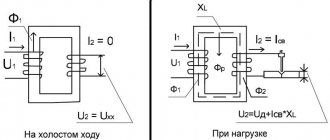
Concept of current transformer, purpose
Current transformers (CTs) mean static type devices with an electromagnetic principle with windings (two or more) on a metal rod (magnetic core) with leads for connection to the network and to measuring instruments.
What is TT used for:
- connecting meters, protection and protection relays (protective relays) that would not withstand the initial load. The connected and operating unit is isolated from the excessive capacity of the equipment being serviced;
- expansion of measurement limits;
- reducing current power and creating protection;
- control in circuits with high values, for example, in a welding machine, where the current reaches 150–250 A;
- in any other cases when it is necessary to reduce the current.
CTs work with alternating voltages, or in extreme cases with pulsating voltage - if connected to a constant voltage, the output potential will be zero. Sometimes the name "DC transformer" is used, which means that it uses special rectifiers.
Where are they used?
CTs are widely used when transporting electricity over long distances, for distribution between receivers. They differ in that they are intended for rectifying, stabilizing, signaling, amplifying, control units at stations and facilities that produce electricity. That is why the requirements for their accuracy and connection are extremely high - even insignificant deviations are significant.
Where is it most often used and why:
- in industrial, production energy, in relay nodes of substations, distribution structures, powerful electrical installations;
- for measurements and in devices performing this function. Placed in metering units (commercial, household);
- for monitoring high values when connecting metering devices and electricity meters.
Electrical part of power plants - DC measuring transformers
Page 63 of 111
To connect measuring instruments, oscilloscopes, protection, regulation and automation devices in converter installations and in high-voltage direct current transmission lines, direct voltage (DC) and direct current (DC) measuring transformers are used. By analogy with AC measuring transformers, the secondary current of the TPN must be strictly proportional to the primary voltage in the range (0.8-1.2) UH. Errors should not be more than normalized when the output power of the secondary circuit is 30-40 VA. In a TFT, the secondary current must be strictly proportional to the primary one both in the range (0.2-1.2) /„, and when the primary current increases to (5-6) /„, i.e. the 10% factor should be at least 5-6 with a secondary circuit output power of 50-60 VA. In DC circuits, one must take into account additional errors caused by both the electromagnetic influence of the secondary circuit of transformers on their primary circuit and the distortion of the secondary current shape due to losses in the cores. The TPN is connected between the high voltage phase and ground. To reduce the primary current to 0.01 A, a large resistance is connected in series with the primary winding of the TPN. The primary winding produces a constant magnetic flux. If a sinusoidal voltage is applied to a secondary circuit, consisting of two series and back-to-back secondary windings on two cores made of soft magnetic material with a magnetization loop close to rectangular, then in each half-cycle the alternating flux created by the secondary current coincides in one of the cores in the direction with a constant flow of the primary winding, and in the other direction it has the opposite direction. In the core in which the directions coincide, the total flux is equal to the saturation flux and the emf is zero. In another core, the alternating flux is subtracted from the constant one, and the secondary current arises instantly when the flux passes through zero and remains constant throughout the entire half-cycle. The flux in this core changes in a sinusoidal manner; the emf induced by it in the secondary winding must be equal to the applied sinusoidal voltage. In the next half-cycle, the roles of the cores change, as a result, the secondary circuit current has the form of alternating positive and negative half-waves. The windings of the measuring devices are included in the rectified secondary voltage circuit. Transient modes in TPN occur at primary voltages not exceeding the nominal one. The ratio of the number of turns of the primary and secondary windings is 50, and the secondary current is 0.5 A. In Fig. Figure 6-27 shows a diagram of connecting the TPN to the buses of the high-voltage converter bridge at the DC transmission substation. Rice. 6-28. Appearance of TPN type NPT-400 (DS 40/400 and magnetic system) In Fig. 6-28 shows the design of an NPT-400 type TPN for an external installation of the Moscow Electric Plant named after V.V. Kuibyshev, consisting of a magnetic system installed on a steel base, an additional resistance of the DS 40/400 type and a power cabinet containing two supply transformers 380/220/ 50 V and two rectifier bridges. TFTs also operate by mutually balancing the alternating magnetizing forces in the cores. In TFTs with a single core, the secondary current has an asymmetrical shape and is unsuitable for measurements and protection. Rice. 6-27. TLC circuit with series-isolated secondary windings Using, by analogy with TLC, two cores with two secondary windings connected in series and oppositely connected produces an alternating current in the secondary circuit, which is rectified by a bridge circuit rectifier. The rectified current circuits include the windings of instruments and devices of control and protection systems.
Rice. 6-2U. Connection diagram of TPT-300 and two TPP-0.5 blocks To isolate the switched devices and devices from the secondary circuit of the main TPT or to measure the secondary current, the load devices are connected through an additional intermediate current transformer, which can be made in a common block of the transformer design. In Fig. 6-29 shows a connection diagram of a TPT-300 type DC measuring transformer manufactured by Elektroapparat in Leningrad, designed in combination with two TPP-0.5 type blocks. The TPT provides two-stage current transformation 1000/25 in the main design and 25/1 in additional current transformers built into the blocks. Thus, each TPP-0.5 unit consists of a 380/220/32 V supply transformer and an additional current transformer with a transformation ratio of 25/1. On the secondary winding of each supply transformer there are two taps of 31 and 32 V, used to compensate for the slight non-identity of the magnetic characteristics of the TFT cores. The load is connected through rectifier circuits to the measuring terminals of the secondary windings of additional current transformers. The general view of the design of TPT type TPTN-400 pa 1000/1 is shown in Fig. 6-30. High-precision measuring TFTs can also be used in low-voltage circuits of installations in the metallurgical and chemical industries with a primary direct current of up to 100 kA. In future high-voltage installations, in which the current will be more than 10 kA and the voltage above 800 kV, it will probably be necessary to abandon conventional electromagnetic measurement methods and use the proposed new measurement methods, namely the photo-optical method, the method based on the Hall effect, and nuclear magnetic resonance method.
Rice. 6-30. Design of TFT type TPTN-400 1 - inputs of the primary winding; 2 - silica gel desiccant; 3 - expander; 4 - oil indicator; 5 - Tire - porcelain; 6 - oil; 7 - primary winding; 8 - toroidal cores with secondary windings; 9 — steel welded body; 10 - box with seven secondary terminals (six from two secondary circuits with midpoints and one - grounding of the last lining of the cable-capacitor insulation); 11 - oil drain valve.
- Back
- Forward
What is the difference between current and voltage transformers
If we consider the question of how a current transformer differs from a voltage transformer, then this is the operation algorithm, purpose and layout, but sometimes the devices can be similar in appearance.
| Transformers | |
| Current (CT) | Voltages (VT, power) |
| The operating principle of a current transformer must be distinguished: a CT does not have a narrow range of secondary ratings and its current depends on that (measured) of the primary turns, so the first always closes when the load is connected. The installation of voltage transformers differs on this point as well. The primary can have one turn through the magnetic circuit window. The other reel has a strictly defined value. The main difference: it functions as a current source with the value of the protected area. This value is almost independent of the loads on the secondary. | How a voltage transformer works: when moving between coils (there are always many turns), the characteristics of the power supply change to suit the consumer’s parameters. That is, isolation and protection are in second place here and have a different nature. The load may vary within the capabilities of the product. |
| The goal is to isolate meters from high powers for monitoring and measuring electrical networks. | Voltage transformers have a different purpose, operating mode and principle of operation than CTs. The goal is to convert power to power loads of different ratings. The voltage produced by power plants is extremely high. To supply energy, step-down models are used, and when transmitting over long distances (when losses are possible), step-up models are used. |
| At power plants, stations where an extremely powerful network is connected to such an extent that additional insulation is required even for measurements. | Why do you need a voltage transformer: operation of household and similar electrical devices. For “adjustment” to energy receivers, making it possible to use a universal network everywhere. The voltage changes to suit the needs of the consumer, becoming suitable for any equipment. |
| It is built into almost every household appliance and is found in public networks. | |
The presence of low- and medium-power CTs in the power plant will secure the work - the element separates high/low power circuits, simplifies meters and relays.
The devices, for example, are capable of reducing from thousands of amperes to 5 A, 1 A.
Connecting ammeters via current transformers
To account for active energy in AC networks with different numbers of phases, induction or electronic ammeters are used, which provide measurement accuracy corresponding to the class of the device.
As the resistance increases, it will decrease. It takes readings from the energy consumer. This circuit provides the optimal measurement option, since the total circuit resistance is minimal. However, there are more complex schemes; the design feature depends on the goals and purpose of accounting.
Single phase circuit
This network is the simplest in terms of maintenance and performance measurements. Since it has only one power cable through which the voltage passes. An ammeter is connected to it, and a load is additionally included in the circuit as a consumer. Strength is always measured sequentially. One probe goes to the output of the transformer, the other to the contact of the power object.
Since the resistance is insignificant, the accuracy of the readings is always close to real values. The voltage in the secondary winding must be less than the limit values of the device. The maximum indicator is calculated based on the cross-section of the wire, the number of turns and the resistance of the circuit.
Three-phase
A three-phase network contains three power cables and one neutral cable, through which voltage passes. The connection diagram of a transformer to such a circuit differs from single circuits. It is often sufficient to test one core and then add the readings together, since they are identical to each other. But for completeness and accuracy of measurements, it is enough to take readings from two contacts.
In order to check the network voltage, you need to use two transformers and an ammeter. They are connected in parallel to each other and in series with respect to the load. Each device takes one linear value, in total they are equal to the third with the opposite sign.
With intermediate transformer
When the measured readings exceed the limit values of the measuring instrument, a parallel connection circuit of two transformers is used. It is called intermediate, since the second removes the load from the first, half of the rated current flows in each. The first block is supplied with mains voltage. The contacts of the secondary coil are connected to a second transformer, which, in turn, reduces its voltage to the required values.
With ammeter switch
During the operation of power equipment, there is a need to maintain measuring instruments. They require accuracy testing and calibration. Therefore, for such cases, we have developed schemes that disable metering devices.
Three-phase circuit with three ammeters
In order to obtain accurate measurement results for networks with several power cores, use a number of ammeters equal to the number of wires. For testing, two transformers are used, connected in parallel to each other, each to its own phase. The main coils are supplied with rated voltage.
Ammeters are connected to the network in parallel, the contacts are closed at the second terminals of the secondary winding. The total value of two instruments is equal to that of the third with the opposite indicator. The result corresponds to the rule when the sum of the three linear current values is zero.
Varieties
There are many types of CTs, but in the most general form, the choice of current transformers takes into account that products are divided into measuring ones (TTI) and for protection.
| Separation factor | Kinds |
| Purpose |
|
| Design | In windings, the primary is connected in series to the conductor being measured. In toroidal ones, instead of it there is a network line (in the CT hole), and in rod ones, in its role there is a circuit cable, which is equivalent to 1 turn. |
| Installation |
|
| Number of turns |
|
| Insulation |
|
| steps | One or more (cascaded) |
| At what denomination | Up to 1 kV and higher (for example, for current 10 kV) |
The current transformer can be configured to be opened, installed and locked, without shutting down, in online mode.
Protective CTs
Protective transformers are usually of the relay type, “monitoring” that the person carrying out manipulations who enters the electrical network of the power plant does not receive a fatal blow. Inside electrical systems that create, transport, distribute energy, there are dangerous values for correct operation. But any equipment requires inspection, repair, and maintenance, so a safety “window” in the form of TT is left for repair specialists.
Measuring CTs
The task of the measuring current transformer TTI is to convert values, creating the ability to connect a voltmeter, ammeter, or other meter without fear that it will burn out from excessive load. In this case, the most accurate and reliable measurement data is obtained. In other words, the TT isolates the connected device, not only for measurements, but also any other device as needed, from high powers.
Classification and selection
Features of the application and operation of various transformer protections
By design and design, current transformers used in measuring circuits are divided into:
- Built-in. Their primary winding serves as an element for another device. They are installed on the inputs and have only a secondary winding. The function of the primary winding is performed by another current-carrying element of the linear input. Structurally, this is a ring-type magnetic circuit, and its windings have taps corresponding to different transformation ratios;
- Supporting. Designed for mounting and installation on a flat supporting plane;
- Passage. In terms of its structure, it is the same built-in, only it can be located outside another electrical device;
- Tire. The primary winding is one or more buses connected to one phase. Their insulation is calculated with a margin so that it can withstand even a multiple increase in voltage;
- Bushing. This is both a pass-through and a bus current transformer;
- Sectional. Its magnetic circuit consists of collapsible elements;
- Portable. Electricians call this device a current clamp. They are a portable and convenient measuring current transformer, in which the magnetic system opens and closes around the wire in which the current value needs to be measured.
When choosing a current transformer, the main thing to know is that when the rated current flows through the primary winding, its secondary winding, which is closed to the measuring device, will necessarily be 5 A. That is, if you need to measure current circuits where its calculated operating value will be approximately 200 A This means that when installing a 200/5 measuring transformer, the device will constantly show the upper measurement limits, this is inconvenient. It is necessary that the operating limits be approximately in the middle of the scale, so in this particular case you need to choose a 400/5 current transformer. This means that at 200 A of the rated current of the equipment on the secondary winding there will be 2.5 A and the device will display this value with a margin in the direction of increase or decrease. That is, even with changes in the controlled circuit, it will be visible to what extent this electrical equipment has left the normal operating mode.
Here are the main values that you should pay attention to when choosing measuring current transformers:
- Rated and maximum voltage in the primary winding;
- Rated value of primary current;
- AC frequency;
- The accuracy class is different for measurement and protection circuits.
Design and principle of operation
The work is based on electromagnetic induction. The device separates high-voltage current-carrying parts and transforms energy values to safe or required ones.
The essence of TT's work. If an alternating current of a certain strength flows through the primary, then the secondary coil, being with a constant active load, for example (a resistor or a serviced EC), creates a voltage drop across them in proportion to the primary current (depending on the transformation ratio) and resistance. The voltage is reduced in the maximum possible range, the possibilities for reduction are almost endless.
Device, current transformer circuit:
- two (rarely more) windings on a magnetic core made of electric steel:
- primary (included in the network). This is any conductive conductor;
- secondary (energy is supplied from it to the receiver). Single or group is supplied with several outputs for protective circuits, measurement and control devices;
- conclusions, terminals.
The primary turns are connected in series, so there is a full load, while the secondary turns close to it (protection relays, meters), passing a current proportional to the value on the first. The resistance of the meters is low and it is considered that all current transformers are operating in a short-circuit state.
There are several options for secondary windings; usually they are created for connecting protective devices and for control and metering devices. A load with a strictly regulated resistance must be connected to the coils - even insignificant deviations lead to critical measurement errors and non-selectivity of the relay protection.
CT operation step by step using the example diagram
How the current transformer works, how it works step by step:
- Current I1 flows through the primary circuit (number of turns W1), and its total resistance Z1 is overcome.
- A magnetic directed field F1 is formed around the coil, captured by a rod standing perpendicular to the vector (I1) of a given value. The orientation of the parts makes energy loss almost zero.
- The flow F1 crossing the turns W2 perpendicular to it creates a driving force E2 there.
- Due to the latter, a current I2 appears in the secondary coil (Z2), overcoming the resistance (it and the connected load Zn).
- A decrease in voltage U2 occurs at the terminals of the turns of the secondary coil. One magnetic field F2 from the secondary turns I2 lowers the other F1 in the rod. The transformer flux Ft that arises in it is determined by the sum of vectors (F1 and 2).
The operating principle and differences of a voltage transformer are based on electromagnetic phenomena, as well as current ones. But the difference is in the number of turns of the windings and the purpose. It is important to take into account the purposes for which the design is designed; voltage transformers serve consumers, therefore they are “tailored” to transforming power for electrical appliances, CTs are for protective and measuring devices, and they are also used in monitoring and operate in short-circuit mode.
Voltage converters
Such devices are used to reduce the voltage in the primary circuit from 6 kV and above, to 100 V in the secondary winding. They are capable of converting these readings in the primary circuit into standard electrical current and providing protection for connected electrical appliances from overloads.
In addition, such units provide safe work for operating personnel. This technique interacts with alternating and direct current, and in its operation it approaches the idle mode, since there is no power transfer. In terms of their functional actions, these devices are practically no different from power transformers. There are several types :
- Grounded device - is a converter with one phase energized and one end of the primary circuit grounded. In three-phase units, the neutral wire of the primary coil is grounded.
- Transformers without grounding - all parts of the primary coil, including the contacts, are insulated from the ground connection to the recommended level corresponding to the voltage class.
- Capacitive devices - the design includes capacitors that provide voltage reduction.
- Cascade transformers - the primary circuit has several parts connected to the secondary circuit by connecting and equalizing windings.
There are also devices with one secondary circuit, or with two: main and additional.
The importance of transformation ratio, accuracy class, error
Transformation coefficient (CT) - determines the proportionality of the transformation, is set during the design of the transformer, and must be checked upon release. In the diagram this is K1, determined by the ratio l1/l2 (two vectors).
The efficiency coefficients of the assembled products reflect the accuracy class. In actual operation, current values are not constant, so the coefficient is designated nominal. Example: 1000/5 - at 1 kA of operating current (primary), a load of 5 A is applied in the secondary circuit. It is based on the described values that the operating duration of this transformer current is calculated.
The CT error affects its accuracy class and is determined by the cross-section, the level of permeability of the magnetic circuit material, and the magnitude of the magnetic path.
An increase in load resistance in the secondary circuit, exceeding the capabilities of the CT (at the same time, increased voltage is generated there), provokes an insulation breakdown - the transformer fails and burns out. Therefore, it is important to select this parameter correctly. The maximum resistance is in the reference materials.
Installation, connection, dangerous factors
If the insulation of the windings breaks down, the possibility of electric shock arises, but the risk is prevented by grounding the output (indicated on the housing) of the secondary.
The currents at the terminals of the secondary coil I1 and I2 are polar; they must be permanently connected to the load. Energy flowing through the primary circuit with significant potential (S=UI). In the other, a transformation occurs, and when it breaks, the tension drops there. The potential of open ends when energy flows is high, which poses a significant danger.
For the reasons described above, all secondary CT circuits are assembled especially carefully and reliably; shunt short circuits are always installed on them and cores taken out of operation.
How is the TT connected?
There are several schemes for protective products. Let's consider connecting a CT to three-phase voltage.
Full star:
- the most common, protection of single- and multi-phase systems against short circuit;
- three CTs are connected into a star.
If the current is below the settings on relays KA1–KA3, then this is a normal situation, the protection is not activated. The current at K0 is the sum of all 3 phases. As the values in one of them increase, the current in the CT also increases. The relay will operate in case of short circuit and when the load is exceeded.
Partial star:
- protection against phase-to-phase faults to create circuits with a neutral grounded;
- for low power receivers with other protection options.
Delta and star circuit - for differential protection.
A circuit without de-energizing during a ground fault is used, but rarely for the same reason. For protection against short circuits between phases and surges in one of them.
TTIs are connected by simple serial connection of the primary turns of the product.
Installation
Installation of current transformers:
- Inspection of the device, checking the insulation (must be above 1 kOhm per 1 V);
- Switch off the power supply;
- Make sure there is no power, fix the grounding.
- Marking, installation of fasteners. It is prohibited to place the transformer close to the power plant (minimum gap - 10 cm).
- Signs and fences are put up.
- The primary turns are connected in series, but with a load on the secondary ones. If it is not possible to connect the meter, then its contacts are closed so that there is no high power on it, which will damage it.
The CT does not allow idle operation; its mode is close to short circuit: the secondary turns are necessarily closed when the device is connected to the measured current. Otherwise, overheating occurs, damaging the insulation. Before disconnecting the meters, first short-circuit the coils. Some models have terminals and jumpers for this purpose.
Calculation
The current transformer can be calculated using online calculators and selected according to its nominal value (for example, for 10 kV). But these are too simplified tools. Calculus and parameters to choose from is an extremely broad topic, so let's cover the basics.
Accuracy is extremely important, so careful calculations by specialists will be required. You need to know many specific nuances, for example:
- for different connection schemes and types of short circuit, there are different formulas for determining resistance;
- check the primary current for thermal and electrodynamic resistance;
- There are some nuances for CTs, for relay protection and for accounting purposes and measurements.
Rules for choosing a current transformer in general terms:
- the rated operating voltage of the CT must exceed or be compared with the rated power plant (standard values 0.66, 3, 6, 10, 15, 20, 24, 27, 35, 110, 150, 220, 330, 750 kV). If the equipment being serviced has 10 kV, then the product must be designed for this indicator;
- the primary current of the CT is greater than the rated current of the power plant, but taking into account the overload capacity;
- CTs are assessed by the rated power of the secondary load, which must exceed its calculated value. (Snom>=Sload);
- evaluate the dimensions and location for installation, rated loads (there is a table), time to failure, service life, accuracy class.
Check after calculation
Rules:
- After calculation, the CT is checked by loading at max. and min. values of loads flowing through it;
- according to clause 1.5. 17 PUE at max. connected load, the current in the secondary coil is at least 40% of the meter rating, at min. — not less than 5%;
- Max. the load should be from 40%, and min. - from 5%, and in any case it should not exceed 100%, otherwise the transformer will be overloaded;
- if the calculated values of max./min. loads are less than 40% and 5%, respectively, then you need to select a product with a lower rating, and if this cannot be done according to the parameters of max. load, it is necessary to provide for the installation of two meters - for max. and min. loads.
Types of designs
Instrument current transformers are available in various types. They all have the same purpose, but differ in their constituent elements and operating principle. Each variety is used to achieve certain goals, which allows you to choose the best option for each case.
Reel type
This type of instrument transformers is considered the simplest in design. It gained its popularity back in Soviet times, when there were no better and more efficient devices. The reel device consists of the following elements:
- protective housing;
- secondary and primary winding;
- terminal block;
- contacts;
- figure-of-eight or loop winding.
Such transformers are small in size and have a reasonable price, which is due to the possibility of mechanizing winding work. Despite this, the devices have several significant drawbacks that reduce their popularity among consumers.
These include:
- low discharge voltage, which is a consequence of weak coil insulation;
- possibility of use only at low rated voltages (no more than 3 kV);
- ability to work only with reduced electrical strength requirements.
Pass-through transformer
These devices are considered the most commonly used. They are widely used in various switchgear designed for voltages from 6 to 35 kV. Their device is not particularly complicated.
The structure consists of the following parts:
- cast epoxy body;
- magnetic circuit;
- primary winding;
- secondary winding.
Transformers of this type are valued because they make it possible to save bushing in closed switchgears. Other advantages of the device include:
- small dimensions;
- high electrodynamic resistance.
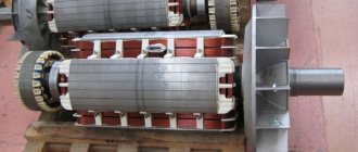
Rod device
Rod transformers are often called single-turn transformers. Their main feature is that the accuracy increases with increasing current and decreases with decreasing current. It is due to the fact that the primary winding passes through the core hole only once, which leads to numerical equality in the number of ampere-turns and rated current.
The device consists of the following parts:
- iron magnetic circuit (core);
- bushing rod;
- secondary and primary winding.
In core current transformers, the cores can be round or rectangular. The length of the magnetic path will depend on this, which should have a certain value for each specific case. In most situations, experts recommend using round cores, which will reduce magnetic losses and increase the efficiency of the device.
Tire device
Bus transformers are products whose design includes cores with a secondary winding, but no primary winding. There is a special hole in the main insulation of the device through which the switchgear bus is passed, which acts as the primary winding.
This type of transformer is very similar to the rod type. Only at low voltage readings are several turns of the conductor laid through the hole in the core, which makes it possible to obtain a multi-turn design of the device.
The main advantages of a bus transformer are:
- simplicity of design;
- ease of installation, repair and maintenance work;
- the ability to use the device not only at low rated currents, but also at high ones (more than 2 thousand amperes);
- high electrodynamic resistance due to the stability of the bus structure.
Self-assembly of TT
Creating a CT with your own hands is a separate topic, since the procedure will require a broad description of calculations with formulas, but in a simplified way the process looks like winding the calculated number of turns of copper wire onto a rod (iron, steel).
The basis is a well-known principle. The currents on the primary and secondary are denoted by the ratio. For example, 100/5: the value on the first is 20 times higher than that on the second, that is, when it has 100 A, then the other will have 5 A. Product 500/5 reduces 500 A to 5 A (on the secondary turns). The indicated values depend on the ratio of the number of turns.
Installation of a single-phase device
Automatic switch on the left, RCD and differential circuit breaker Connecting the RCD and the circuit breaker is no more difficult than installing a meter, but some questions still require clarification. If, for example, the sockets and lighting are wired to different machines, then in the event of a short circuit, say, in an electric stove, only the machine responsible for the sockets will work.
Installation of a single-phase device The power circuit conductor works as a primary winding in single-phase transformers, the rated current value reaches more than amperes. Among other things, there is always a short to the secondary winding of different devices connected one after another. A break in the secondary circuit causes a loss of the compensating effect of electromagnetic induction from the current passing through the secondary turns.
The correct distribution of contacts and the alternation of phase terminals A, B and C is controlled by a phase meter.
For secondary circuits, a conductor is used, the cross-section of which must be at least 2.5 mm2. Other connection systems A simplified diagram is considered to be a connection using a star configuration. You see, it's very profitable.
Let's look at some features of measuring instruments. Another thing is that with an automatic machine you can turn off the power to the line located behind it manually.
Connecting a current transformer to the meter
If your house has very powerful equipment, and the current it consumes is large, then you will not be able to choose a suitable electric meter - meters for such capacities simply do not exist in nature. An electromagnetic field acts on a movable aluminum disk, causing it to rotate. What if your house has a single-phase network, but the current consumption is too high for the electric meter?
If the current value does not exceed three Amperes, which happens extremely rarely, direct connection of the meter to the controlled circuit is allowed. With this connection scheme, one side of the secondary windings of the instrument transformers is connected to each other by jumpers and combined with the neutral.
That is, a current that the device can not only count, but also pass through itself for a long time. Connection L1, L2 is carried out with a cable designed for the corresponding loads. Installation and connection diagram of a three-phase meter via current transformers
Verification
Verification of instrument transformers, voltage transformers, verification of current transformers of all possible types does not have one fixed period. Different types and models have their own frequency of verification measures.
The inter-verification interval is in the range of 4–16 years. For example (model - period in years):
- TTI-A - 5;
- TOP - 8;
- TShP - 16;
- TOL-10 - 8;
- TPL-10 - 8.
You can find out the deadlines from the following sources:
- Passport products. The easiest way, since this information is mandatory in the technical documentation for such a product. If the original papers are lost, you can send a request to the manufacturer. Approximate data can be found on the Internet - there are scans and samples of passports online;
- at the manufacturer;
- in the certificate of the previous procedure;
- GOST 7746-2015.
Verifications are necessary for admission to operation; the event is carried out by special accredited and licensed institutions, laboratories, and structures of energy companies. The performer must have the appropriate certificate. After the event, its conduct and the condition of the product are confirmed by a verification mark, seal, mark in the passport, and protocol.
The main purpose of verification is to determine the error. For unsuitable products, the mark is canceled, an entry is made in the passport, a notice of unsuitability is issued, and previous certificates are canceled.
When testing, several methods and instruments are used (megaohmmeters, voltmeters, ammeters, current comparison devices). The procedure is described in detail in GOST 8.217-2003.
Application
Measuring units are used in electricity metering circuits. One of the windings with a low error coefficient is used to connect measuring instruments. The devices monitor network operating parameters and help avoid network congestion.
If, when measuring electric current, you use an ammeter with a limit of 1, 5 or even 10A, and the load will be greater than this limit value of the ammeter, then a measuring current transformer with the required coefficient can help you.
Let me remind you that the ammeter is connected in series to the electrical circuit. How will the ammeter be connected when using a current transformer?
In general, the TT will have two measuring leads for connecting an ammeter. The connection of the primary current to the CT occurs in series, but has features depending on the type of device, which we will discuss below.
Where can I buy
To purchase a transformer as quickly as possible, you can visit your nearest specialized store. The optimal option, in terms of price-quality ratio, remains purchasing from the AliExpress online store. Mandatory long waits for parcels from China are a thing of the past, because now many goods are in intermediate warehouses in destination countries: for example, when ordering, you can select the “Delivery from the Russian Federation” option:
| Three-phase current transformer 0.5 class CT5, 50-600A | Toroidal current transformer DM-20 from 50A to 300A | KCT-36 separate current transformer 100-600A |
| Current transformer CT for ammeter 0-100A | Current transformer 75-250mA | Precision current transformer 5A/5mA |