Technique of operations with disconnectors and separators
Before turning on (turning off) disconnectors (separators), their external inspection should be carried out. At the same time, there should be no damage on the disconnectors, their drives, as well as blocking devices that could interfere with the execution of operations.
Operating personnel do not have the right to operate disconnectors (separators) that have cracks in the insulators. It is worth noting that you should not perform operations with these devices under voltage if it is possible to perform all operations after removing the voltage from them by turning off the corresponding switch.
A manual disconnector must be turned on quickly, excluding shocks at the end of the stroke. If an arc occurs, the knives should not be retracted, since when the contacts open, the arc may lengthen, closing the phase gap, causing a short circuit.
In all cases, the switching on continues until the end, and the arc, when the contacts touch, will go out without damaging the equipment.
On the contrary, you should disconnect the disconnector carefully, slowly, first making a test movement with the drive lever in order to make sure that the rods are in good condition and that the insulators are not broken.
If, when the contacts diverge, a significant arc occurs, then the disconnector must be turned on immediately and the reasons for the formation of the arc must be found out. An exception can be considered the disconnection of charging and magnetizing currents by disconnectors (separators). In these cases, operations are performed quickly, which ensures rapid extinction of the arc.
Operation of single-pole 6-10 kV disconnectors, which is carried out using operating rods, should be carried out in the order that poses the least danger in case of mistaken shutdown of the device under load.
With a mixed load, it is safest to turn off the first of the 3 disconnectors in turn, since this will not cause a strong arc.
When the knife leaves the sponge, a small voltage difference may appear between them, because on one side of the knife there will be the voltage of the power source, and on the other side, approximately the same EMF will be maintained for some time, which is induced by asynchronous, synchronous load motors rotating when powered in two phases.
When the second disconnector is turned off, a dangerous arc may appear, and when the third disconnector is turned off, no power is switched at all. Due to the fact that disconnecting the second disconnector in turn is the greatest danger, it must be mounted as far as possible from the disconnectors of other phases.
It is for this reason that the disconnection of a single-pole disconnector begins with the middle phase disconnector, any of the two extreme blades is disconnected second, and then the remaining extreme one. We must remember that switching on is carried out in reverse order.
When switching magnetizing currents and charging currents with disconnectors (separators), personnel must know in advance the magnitudes of these currents.
In 35-220 kV networks that have disconnectors and separators connected in series, switching of charging and magnetizing currents is best done using separators.
When disconnecting unloaded transformers by separators, it is better to reduce the magnetizing current in order to reduce arcing, which is achieved by moving the transformer on-load tap-changer to a position that corresponds to the rated voltage.
When disconnecting an unloaded transformer in phases, you must start with the middle phase, and then the poles of phases A and C are disconnected one by one. At the moment of switching on, phase B should be switched on last.
Actions with disconnectors
Operational switching at thermal power plants Read more: Sequence of production operations
3. Actions with disconnectors
Activation of the disconnectors by both manual drives and a rod must be done quickly and decisively, but without impact at the end of the stroke.
Retracting the disconnector blades when approaching the contacts (jaws) is strictly prohibited, as this leads to accidents.
In the on position, the disconnector knives must fully engage the contacts (jaws).
Switching off the disconnectors should be done slowly and carefully. If an arc occurs at the moment the knives move away from the contacts, the disconnector must be quickly turned back on; the operation should be stopped until the causes of the arc are identified.
In the off position, the disconnector blades must be completely (to the point of failure) retracted from the contacts.
4. Actions with switches
Turning on the switch by hand should be done quickly, bringing the stroke of the interval or lever to the stop; At the same time, the “on” signal lamp should light up.
When turning on remotely, depending on the type of contactor, pressing the “turn on” button or turning the control key must be done until the “on” signal lamp lights up.
The switch must be manually turned off by lightly turning the steering wheel all the way or turning the lever drive, as well as by pressing the drive latch, pressing a special button or the core of the tripping coil. The “disabled” indicator light should light up.
When turning off remotely, the corresponding action with the control key or button must be continued until the “off” lamp lights up.
Checking the position of the circuit breaker after tripping is mandatory in all cases where there is an operation with disconnectors following this trip, except in cases where the disconnectors are controlled remotely.
Operations with disconnectors must be preceded by removal of the operating current from the switch, with the exception of cases of transfer from one bus system to another when the switch of the given connection is turned on.
The operating current is removed by a fuse in the switching solenoid circuit until the switch position is checked.
Compliance with this sequence when performing these operations fully ensures reliability, because not all switchgears (RU) have fuses for operational current circuits located next to the switches.
When performing operations in switchgear, where the fuses of the operating current circuits are located far from the switch, during the time from checking the position of the switch to removing the operating current from the drive, a change in the position of the switch may occur (erroneous switching on of the switch, switching on of the switch due to a double ground fault in the operating current circuit and etc.).
Subsequent operation of the disconnectors while the circuit breaker is in the closed position may result in equipment damage and serious personal injury.
Checking the position after switching on is mandatory at the bus coupling switch (SHSV) before starting to transfer connections from one bus system to another.
The actual position of the switch should be checked mainly by the mechanical indicator. Signal lamps and measuring instruments for this connection can serve as auxiliary means. For air circuit breakers with separators and circuit breakers of the VMG and MGG types, the position of the circuit breaker is checked by inspecting the working contacts.
5. Actions with relay protection and electrical automation devices
All operations with relay protection and electrical automation devices are carried out only with the permission of senior operating personnel.
When eliminating an accident, personnel can act independently and then notify a higher-ranking operational worker.
Equipment, buses and lines that are under load or live should not be left unprotected; Also, generators, synchronous compensators and transformers should not be left without protection from internal damage.
Before disabling relay protection upon request, operating personnel must make sure that other protection is turned on, providing reliable protection of the equipment, or take measures to replace the disabled protection with backup protection, or the equipment is switched on to a backup bus system via a bus system with appropriate protection.
When changes are made in the main (primary) circuit diagram, it is necessary to promptly disable, enable or change the settings of relay protection devices and electrical automation in accordance with local instructions.
If the load current of the connections exceeds (the maximum permissible value according to the conditions for setting up relay protection), it is necessary to take measures to unload it.
When testing equipment, before turning on the circuit breaker, personnel must make sure that the circuit breaker is in working order, that there is operational current in the protection circuits and controls of the circuit breaker, and that at the connection being tested all (including high-speed) protections are turned on and set in the position corresponding to testing ( if necessary).
The action of automatic reclosure and automatic transfer from the circuit breaker used for testing must be disabled.
When testing the ShSV or bypass switch, you must turn on the protection of the ShSV or bypass switch against all types of short circuits with settings as specified in local instructions.
When automatically turning off or on switches, operating personnel must:
a) according to the alarm, establish and record which switches have turned off and acknowledge their control keys. At the same time, on circuit breakers with automatic reclosure, key acknowledgment is allowed only after the personnel are convinced that the automatic reclosure device has returned to its original position;
b) carefully inspect and record on which relays the signal flags have fallen off and what time is recorded by the time relay indicators, then set the flags and indicators in the desired position and inform the higher operational personnel (if there is a second person on the control panel, the inspection of the signal relays is carried out by the personnel together, i.e. i.e. with a controlling person);
c) release relays that have self-holding (for example, on gas protection of transformers) and lift the loads of switches with load drives activated by automatic reclosure or automatic transfer switch;
d) bring into compliance with the primary connection diagram the automation and relay protection devices that have keys, disconnecting devices, switches and breakers, the position of which depends on the primary connection diagram;
e) after automatic shutdown, inform the local relay protection and electrical automation service about dropped flags of signal and other relays, about the readings of time indicators and the launch of automatic oscilloscopes, etc.
In case of sudden changes in voltages and currents in the network, not accompanied by switches being turned off or on, personnel are required to inspect the relay protection and electrical automation panels and record the operation of all signal relays.
When a ground signal is detected on a DC power supply, personnel must immediately take action to locate the insulation fault and correct it in accordance with local regulations.
Operational switching at thermal power plants Read more: Sequence of production operations
Information about the work “Operational switching at thermal power plants”
Section: Miscellaneous Number of characters with spaces: 26527 Number of tables: 2 Number of images: 3
Similar works
ISTU electric boiler house project
222453
50
17
… current frequency Norm. led Remote control, at t, s 0.01 - 0.08 over 1 Variable f = 50 Hz UD ID 650 V - 36 V 6 mA Variable f = 400 Hz UD ID 650 V - 36 V 6 mA Constant UD ID 650 V 40 V 15 mA The electric boiler room, where the main 6 kV equipment is installed, belongs to the class of especially dangerous premises in terms of the degree of damage ...
Running-brake stand
60724
2
0
… . Take measures to reduce voltage fluctuations in the electrical network 4 During hot running in, when the rheostat electrodes are completely buried in the solution, the electric machine does not develop braking power. The concentration of soda in the solution is low. Increase the amount of soda in the solution to 2-3%. Low temperature. Check the proper operation of the temperature regulator. Large deposits of soda. on the electrodes...
Combined-cycle plants
157736
17
0
... installations. They are characterized by high thermal efficiency, good maneuverability and environmental characteristics, high reliability and relatively low cost per installed kilowatt. Combined-cycle plants intended for St. Petersburg must be adapted to the operating features of the Lenenergo power system. This is a significant unevenness of daily and weekly consumption...
Design of the electrical part of a 180 MW thermal power plant
133694
40
143
... The tariff for electricity on the buses of thermal power plants is adopted in the amount of 20 kopecks/kWh, the tariff for heat energy is adopted in the amount of 100 rubles/Gcal.5.8.4. Production plan The installed capacity of the thermal power plant is 180 MW. The construction period in accordance with building codes is five years. The launch of the first power unit is planned for the twenty-fifth month from the start of construction. The input step for subsequent blocks is twelve...
Device
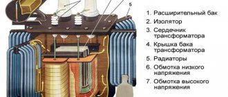
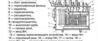
The design of disconnectors can be studied using the example of a switching device with 3 poles, a chopping type.
It consists of three poles located on one frame. All poles have two contacts: movable and fixed. Movable types of pole terminals are fastened with insulators with one shaft. The shaft is also connected to the lever of the device’s drive mechanism. When controlling the disconnector mechanism, all three knives are immediately turned on simultaneously.
The connection of the contacts is made rigid using special springs. They press on steel plates and press the moving contact knives against the stationary one.
During a short circuit, a large current passes through the disconnector, which leads to its destruction. To solve this problem, a magnetic lock was built into the design of the disconnector, which includes 2 plates located on the sides of the moving contact. These plates are magnetized by the action of short circuit current, strongly attracted to each other, and create additional elasticity between the contacts.
The design of the disconnectors does not provide a device for extinguishing the electric arc, therefore, when the load is on, it is prohibited to turn off the disconnector. Other devices, such as switches, are designed for such purposes. To prevent the circuit from being switched off by the disconnector when the load is on, their design includes mechanical interlocks. Mechanical clamps are also used for these purposes.
Requirements for disconnectors
The following requirements are necessary for servicing disconnectors by an electrician or other maintenance personnel:
- The design of the disconnectors is such that a circuit break according to the voltage class is visible.
- Drives must be equipped with rigid fastening of knives in the off and on position. There should also be good stops to limit the rotation of the knife more than expected.
- Disconnectors must be suitable for all weather conditions.
- Insulators and rods must have sufficient strength and not be destroyed when switching.
- The main blades of the disconnectors must be equipped with an interlock with grounding blades that does not allow simultaneous switching on.
Operating principle and switching procedure
In switchgears, operations with disconnectors should be carried out only after the disconnected state of the circuit breaker has been verified.
Before disconnecting the disconnector, you need to inspect the entire structure from the outside. The disconnectors, interlocking devices and their drives must be free of damage that could interfere with the shutdown operation. It is especially necessary to inspect whether there are any shunt jumpers for the disconnectors.
If any defects or malfunctions are found, then turning off the disconnector must be done carefully, with the permission of the official who ordered the switching. If cracks are detected on the insulators, it is prohibited to perform any operations with the disconnectors.
With a manual drive mechanism, the disconnector must be turned on quickly and carefully, and there should be no impact at the end of the stroke. If an electric arc appears during switching on, then the knives cannot be pulled back, since the size of the arc will increase and block the interphase space, causing a short circuit. In any case, the operation must be completed. When the contacts close, the arc will disappear and will not create any problems.
The reverse operation to disconnect the circuit is carried out slowly and with caution. First, make a small movement with the lever to check the action of the rods, breakage of insulators, and play in connections. If an arc appears when the circuit is disconnected, then you need to immediately return the disconnector back to its place and find out the reason. It is prohibited to do this until the switch is clarified.
Switching off single-pole disconnectors
Such operations are carried out with special rods, in a certain sequence, to ensure maximum protection of personnel. Let's imagine a case where an electrician began to shutdown by mistake, without disconnecting the load.
With the load turned on, it is not dangerous to turn off the 1st disconnector, since a strong arc does not form. When disconnecting the contacts, only a small voltage can occur; on the one hand, the disconnector will have the source voltage, on the other, there will be the same potential difference, which is induced by running motors, as well as by capacitors available in the network.
When the 2nd disconnector is turned off, a powerful arc may occur. There will not be much power at the 3rd disconnector. Therefore, no matter how the disconnectors are located, the middle disconnector must be turned off first, then the upper one, then the lower one (if vertically positioned). If the location is horizontal, then the principle is the same, only instead of top and bottom, you need to turn off right and left in any order.
If the switches are equipped with springs, then you need to work with the disconnectors by first loosening the springs on the switches, in order to avoid accidental operation of the switches when operating the disconnectors.
On a 6-10 kilovolt line, where there is current compensation for grounding, before turning off the magnetizing current, first turn off the arc suppression reactor to avoid overvoltages. They can arise due to non-simultaneous decoupling of phase contacts.
Features of application
Disconnectors serve to visibly disconnect a section of an electrical circuit during equipment repair, create safety, and exclude power supply to the repair section. Also, releases can be used to switch electrical power from one circuit to another.