zom81e › Blog › About installing relays in theory and examples. Part 1
Quite often I have to help with connecting fog lights and other additional equipment.
The main problem that novice cadet teachers and others face is connecting the relay. To help in this matter, it was decided to make instructions for this process, or rather a short series of posts devoted to this topic. Task.
We have at our disposal an OPEL KADETT car, in which fog lights have never been installed before. The existing configuration did not include any wiring for this, and I really want to install a set of universal fog lights. Therefore, we will carry out the installation, as they say, from scratch. They say that they need to be connected via a relay. What does it look like, what does it do and most importantly, how do you connect it? I won't explain all of this. There are plenty of articles on the Internet with this information. Here we will only consider connection options.
Solution.
We go to the market/to a car store/via a browser to an online store, etc. and buy the set of fog lights you like. If you didn't save money, the kit will include all the necessary installation elements. If you still want to save money or got the headlights from your brother/godfather/neighbor, then you need to buy something extra. Further, I will not stipulate that you need wires and corresponding terminals, but will focus only on the main elements. To turn on and off additional headlights in a timely manner, we will need a button. There is no way without this, because we all know the rules of the road. To do this, purchase the one you like (preferably with backlighting and position indication) and embed it into the panels in a place convenient for you, or buy a standard button. Of course, I will not describe the first option, because I cannot predict the future, and especially yours. But if you settled on a standard button, then the diagrams indicate the numbers of contacts that correspond to it. All contact numbers on buttons/relays/switches, etc., which are in the diagrams below, can be found on their body or plug/connector in the form of small numbers in the appropriate places. So, relay. There are mainly 3 types of automotive relays available on the shelves.
Option 1.
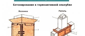
4-pin with built-in fuse. I believe that this is the most successful option for installing such equipment. The advantages of this design are that the number of handmade twists/solders along the power wire path is reduced, which has a positive effect on the reliability of the wiring and the voltage drop along the way to the consumer. There is also a drawback - if the installation location is poor, where the relay can get into an aggressive environment such as moisture, the contacts may become contaminated. The latter impairs conductivity, which can lead to failure of the relay itself and worsen the performance of the consumer. In the worst case, the wires may be destroyed. But this is unlikely. Such a relay looks like this:
The connection diagram in this case will be like this:
Option 2.
4-pin regular relay. A very rare guest on the shelves today (at least I rarely saw them), but often found in the bins of experienced drivers of the Soviet era. It looks like this:
To connect using this relay, it is additionally necessary to provide (read purchase) the installation of a fuse to prevent negative consequences in the wiring. I advise you to pay attention to special holders. They look like a plastic fuse housing. There are also “rubber” versions with increased moisture resistance. We buy what we like. In general they look something like this:
I recommend connecting with this type of relay according to the following diagram:
Option 3.
5-pin regular relay. Perhaps the most common type. Looks like that:
It is with this that connection difficulties most often arise. What else is typical for this type of relay is that you can easily buy a block/connector for them. Then this set will be something like this:
Installation using this block certainly makes the process much easier, but unfortunately it also has a drawback. These are just another twisting/soldering of wires. So everyone is free to do their own thing: simply crimp the wires with terminals, crimp and install them in the block (the most correct, but expensive and time-consuming option), “twist” the standard wires of the block with your own wiring. As in the previous case, you will also have to install an additional fuse. And of course, the connection diagram with this type of relay is presented below:
The following symbols are used in the diagrams presented above:
My circuits will work as follows. When you turn on the headlights (+ illumination of the instrument panel and some switches), the button illumination will light up and it will be possible to turn on the fog lights. The same will happen in low/high beam. When the lights are turned off, the PTF will also turn off. Let me remind you that according to traffic regulations, you cannot use PTF with high beams. Therefore, these circuits are made with the simplest connection method in mind and for a conscious driver who does not forget about his switches. If you follow the rules and regulations, then all circuits will require the addition of another relay, which will turn off the PTF in high beam mode. If anyone is interested, I can add more.
Another issue that must be resolved when preparing a new branch of electrical consumers is the fuse rating. In the diagrams above, it is 20 A. This was done on the basis that most relays sold are designed for maximum currents of about 30 A. That is, if during the calculation it turns out that consumers need a current of more than 20 A, I advise you to complicate the circuits and use several relays for each individual or group of consumers. Looking ahead a little, I will say that for installing PTFs with lamps with a power of 90...100 W, these ratings are quite sufficient. Now a little more specific. There is a formula that is included in the basic course of the school curriculum. But we were at school for a long time. Let us remind you: electrical power is equal to the product of voltage and current (P = U*I). Let's look at the most common options: For two PTF lamps with a power of 55 W each, a current rating of (55 W * 2 headlights) / 13 V = 8.5 A is required. That is, the fuse must have a minimum rating of 10 A. But taking into account such a thing as starting current, it is recommended increase this number by 1.2...1.5 times. Those. the optimal fuse would be a 15 A rating. For two PTF lamps with a power of 100 W each, a current rating of (100 W * 2 headlights) / 13 V = 15.4 A is required. In this case, it is necessary to install a fuse with a rating of 20 or 25 A.
Double-action fuses (two-element, time-delayed)
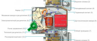
The single-element fuses discussed above are optimal for protecting circuits with constant current consumption or with slight fluctuations. To protect circuits with large fluctuations in current consumption and frequent excesses of the values characteristic of the steady state (electric drive, transformers, etc.), single-element fuses must be selected with a 3–4-fold margin, which can reduce the reliability of protection in emergency overload conditions . Double-action fuses (otherwise known as two-element or time-delay fuses) make it possible to provide more reliable protection for consumers in networks with a wide range of operating overload currents. The operation of fuses is based on the fact that in the event of an overload current, an element of one type is triggered, and in the event of a short circuit, another type is triggered, similar to the element of the fuses discussed above. Both elements are made in a single structure and are electrically connected in series. A view of part of such a structure is shown in Fig. 7.
Rice. 7. Simplified structure of double action fuse element
Rice. 8 demonstrates the operation of a two-element fuse in the event of an overload current in the circuit. Under the influence of an overload current, soldering is heated, made with a special alloy with a calibrated heat capacity, thermal conductivity and melting point. When the soldering alloy reaches the melting temperature, it softens, and a special burst spring abruptly breaks the contact. The resulting electric arc quickly extinguishes due to the distance to which the elements are separated. Due to the significant mass of the solder and holder, this protection element has a large thermal time constant and is not current-limiting; accordingly, it cannot be used for high-speed protection against short-circuit current. In the event of exposure to short circuit current, the protective functions in double-action fuses are performed by the meltable sections of the jumper (Fig. 9).
Rice. 8. Double action fuse tripping due to overload current
Rice. 9. Double action fuse tripping due to short circuit current
The arc that lights up in the places where the jumpers melt quickly goes out, both due to the rapid evaporation of the metal of the jumper and an increase in the length of the arc with a corresponding increase in resistance, and due to the action of the bulk filler, which quickly absorbs the heat generated by the arc, thereby reducing the degree of ionization and conductivity arcs. Penetrating into the space formed due to the rupture of the jumpers, filler particles increase the length of the arc and, when melted, help isolate the surfaces of the jumper elements from each other. The processes occurring in this element when exposed to short circuit current are completely similar to the processes in single-element fuses.
The fuse designs discussed above are used only at low voltages in the protected circuits (maximum units of kilovolts). If the voltage in the circuit has any significant value, approximately above 1500–2000 V, then the arc-extinguishing ability of the bulk filler is not enough to extinguish the arc in small gaps of the fusible jumper. To operate in circuits with voltages above 2–3 kV, specially designed fuses are used. In Fig. Figure 10 shows a schematic section of a high-voltage fuse, designed to operate in circuits with voltages up to several tens of kV.
Rice. 10. High voltage fuse design with arc extinguishing
When exposed to overload current or short circuit current, the working element (usually, for stability of fuse characteristics under the influence of corona discharge and the surface corrosion caused by it, is made of pure silver) softens (or melts) and, by the force of the breaking spring, quickly (a few milliseconds) moves away from the stationary contact point. The arc that lights up in this case is drawn into an area surrounded by an arc-extinguishing material, in particular, boric acid, which, under the influence of the high temperature of the arc, instantly decomposes into water and boron oxide. The decomposition of the arc extinguishing material occurs very quickly; a large amount of water vapor sharply cools the arc and at the same time reduces its conductivity. When the fuse is triggered, within a few milliseconds the arc extends to a length of 5–30 cm (depending on the design of the device) and goes out, thereby providing current-limiting properties. Since significant excess pressure is created inside the fuse body during operation, a pressure relief valve is usually provided at the terminal of the fixed contact point. The housing of the high-voltage fuse is made of materials with high electrical and mechanical strength and low tendency to split. This can be glass fiber reinforced polymer, ceramics and special grades of glass. The presence of a moving element allows you to easily monitor the condition of the fuse. Such elements include combustion indicators and special microswitches, which directly send a signal to the dispatch system about the combustion of a fuse in a specific circuit. Low-voltage double-action fuses are often equipped with similar devices.
The main functional characteristic of any fuse is its time-current characteristic, and it is always given in the manufacturer’s reference data for any type of fuse. This characteristic shows the dependence of the time for complete circuit break on the current through the fuse. The stronger the dependence of the response time on the current, the more reliable the circuit protection will be provided by the fuse in short circuit mode. On the other hand, under operating overloads, the fuse should not burn out for a long time. A typical time-current characteristic of a modern double-action fuse is shown in Fig. eleven.
Rice. 11. Typical time-current characteristic of a double-acting fuse
With a rated current of 200 A, the fuse should operate indefinitely. The characteristic shows that as the current decreases, the response time in the region of low currents increases rapidly; the dependence curve should ideally asymptotically tend to the straight line I = 200 A for time T = +∞. Let us pay attention to the fact that in the area of operating overloads, that is, in the case when the current through the fuse is within the range of (1...5)xIn, the response time of the fuse is quite long, in any case, it exceeds a few seconds. So, for our example, with a current of 1000 A, the response time is 10 s. This type of dependence allows the protected equipment to operate freely over the entire range of operating overload characteristics.
With a further increase in current, the slope of the time-current characteristic quickly increases, and, already with an eleven-fold overload, the response time is only 10 ms. A further increase in the overload current reduces the response time to an even greater extent, although not as quickly as in the area between five and ten times the overload. This is explained by the finite rate of arc extinction due to the finite heat capacity of the filler material, the finite heat of fusion of the fusible bridge material, and the certain mass of the melting and evaporating bridge metal. With a further increase in current (more than 15–20 times the rated value), the response time of the fuse element can be 0.02–0.5 ms, depending on the type and design of the fuse.
Another important characteristic of a fuse as a protective device is the so-called protective indicator, called I2t in foreign sources. For a protected electrical circuit, the protective indicator is the amount of heat generated in the circuit from the moment an emergency occurs until the circuit is completely turned off by the protective device. The value of the protective indicator of a particular device, in fact, determines the limit of its resistance to thermal destruction in emergency modes. When calculating the value of the protective index, the effective value of the current in the circuit is used.
For fuses, the protective indicator consists of two components:
- Protective melting index, that is, I2t during the melting of the jumper.
- The protective indicator of arcing, that is, I2t during the existence of the arc in the fuse.
The overall protective index of the fuse is calculated as the sum of the above values, and its value is usually given in the reference data.
Information about the value of the protective index greatly facilitates the selection of a fuse to protect semiconductor devices. In general, the value of the protective index of the fuse must be less than or equal to the value of the protective index of the semiconductor device.
If it blows out in the wilderness: how to safely restore a car fuse?
Today we will blaspheme a little. Let's desecrate the most sacred thing in a car's electrical system, namely fuses! Let's learn how to do correctly and relatively safely what is strictly forbidden to do - install shorting jumpers, or in common parlance - “bugs”...
The fuse is one of the oldest electrical devices. The inventor of the fuse is believed to be Louis Francois Clément Breguet, a French electrical engineer. In 1847, he conducted a series of experiments and found out that inserts made of thin wire of a fixed cross-section are capable of burning out when the current in the electrical circuit exceeds a certain strength proportional to the cross-section. The practical use of fuses as devices began approximately in the middle of the 19th century - first in industrial and household electrical engineering, and with the widespread use of “steel horses” - in automotive applications.
Despite the invention of various types of automatically reset fuses - spring, bimetallic, semiconductor - the most common disposable fuse by Louis Breguet is still the most common and effective device for protecting electrical circuits in any car from current overload and short circuit.
In both budget and premium cars, almost all electrical consumers are protected by fuses. And in the manual for any car, and even more so in the maintenance and repair manual, there is always the following (or very similar) phrase:
It is prohibited, even temporarily, to install jumper wires in place of the corresponding fuses, as this may damage the electrical wiring and cause a fire!
It is said correctly, and we do not intend to argue with it. However, we note that there are all sorts of circumstances, including not quite ordinary ones. And any owner of a car that is middle-aged and has seen life may find itself in a situation where some important fuse for driving has burned out - in the circuit of the fuel pump, ignition, windshield wipers in the rain, headlights at night, etc., and there is nothing to replace it with. This can happen not only in the city, where there are a lot of car shops, sympathetic citizens, as well as car services and tow trucks, and finally, but in the wilderness, when there are no spare fuses in the stash, there are no shops or just kind people nearby, but you still need to go...
Conditions for selecting fuses
Nowadays, circuit breakers (CBs) from both foreign and domestic manufacturers are becoming increasingly popular, this is primarily due to the fact that circuit breakers do not have the disadvantages of fuses. But despite all their shortcomings, fuses are still actively used, since they are the cheapest option for protecting the connection.
For example, at our enterprise, if the customer does not object, to protect motors with a power of up to 100 kW, a fuse-disconnector is used, given that short circuits are not such a common occurrence, a fuse is a very good solution for protecting the connection.
In this regard, in this article I will tell you how to choose the right fuses with fuse-links in accordance with the PUE and other reference literature, so that your fuses operate only under abnormal operating conditions of electrical receivers.
When choosing a fuse, the following conditions must be met:
- The rated voltage of the fuse must correspond to the mains voltage:
Unom = Unom network (1)
- The rated disconnecting current of the fuse must be no less than the maximum short-circuit current. at the installation location:
Inom.f>Imax.short circuit (2)
Conditions for selecting fuse links:
- the fuse-link current must be greater than the maximum current of the protected connection:
In.sun. > Iwork.max. (3)
- when protecting a single asynchronous motor, the fuse-link current is selected taking into account the motor starting:
In.sun. > Istart motor/k (4)
Where:
k – coefficient, taken equal to 2.5 according to [L1. With. 124,125], which corresponds to PUE clause 5.3.56, for electric motors with a squirrel-cage rotor at a low switching frequency and easy starting conditions (tp = 2-2.5 sec.).
Typically, this coefficient is accepted for motors of fans, pumps, main drives of metal-cutting machines and mechanisms with a similar operating mode.
For engines with severe starting conditions (tп > 10-20 sec.), for example for engines of mixers, crushers, centrifuges, ball mills, etc. And also for engines with high switching frequencies, i.e. for crane engines and other mechanisms of intermittent operation, the coefficient k is taken equal to 1.6 - 2.
For motors with a wound rotor, the coefficient k is taken equal to 0.8 – 1.
When selecting the fuse-link current according to condition (4), it should be taken into account that over time the protective properties of the fuse-link deteriorate, because of this there is a possibility of false combustion of the fuse-link when starting motors. As a result, the engine may not start at all, or may operate in 2 phases, which leads to overheating of the engine.
And if overload protection is not provided, the motor may fail.
The solution to this problem is to select a higher fuse-link current than according to condition (4), if this is acceptable in terms of sensitivity to short-circuit currents.
When protecting an assembly, the fuse-link current is selected according to three conditions:
- for the highest continuous current:
- at full load of the assembly and starting the most powerful engine:
- when starting engines:
where: k – coefficient taking into account engine starting conditions;
— the sum of the starting currents of self-starting motors;
— the sum of the maximum operating currents of electrical receivers, except for the motor with the highest starting current Istart.max.;
To check the reliable operation of the fuse at the end of the protected line, it is necessary to perform a short circuit at the current multiplicity and take into account the shutdown time.
In the reference literature, you can find the following statement: for reliable and quick burnout of the fuse link, it is required that during a short circuit at the end of the protected line, the required short circuit current ratio is provided, i.e. the ratio of the short circuit current Is to the rated current of the fuse link In.vs .
This condition was taken from the old PUE sample 1986, paragraph 1.7.79 (for a non-explosive environment: kкз = Iкз/In.вс (kкз >3), this clause in the 7th edition of the PUE was changed, and now the shutdown time must be taken into account in the TN system, according to table 1.7.1.
For an explosive environment, according to the PUE 7th edition, clause 7.3.139, the short circuit current multiplicity condition must be met: kkz = Ikz/In.vs (kkz >4). This paragraph remained unchanged when compared with the 1986 PUE, which is very strange, considering that paragraph 1.7.79 has changed.
If you do not know the values of the motor starting currents, then as an exception, you can select the rated currents of fuse links for motors with a power of up to 100 kW and a starting frequency of no more than 10-15 per hour as follows [L2. With. 15]:
- at Un.network = 500 V In.vs = 4.5*Рн;
- at Un.network = 380 V In.vs = 6*Рн;
- at Un.network = 220 V In.vs = 10.5*Рн.
After you have chosen a fuse, you need to check the selectivity of the fuses connected in series with each other, taking into account the protective characteristics.
This means that in the event of a short circuit, only the fuse link and the fuse that is closest to the point of damage should burn out. As practice shows, to ensure selectivity between two fuses connected in series. It is necessary that the fuses differ from each other by two steps on the scale of rated currents. In this case, the inserts must have the same protective characteristics, so you need to choose fuses of the same type.
That’s basically all you need to know about choosing fuses; if this information is not enough for you, I recommend that you read the literature that I used when writing this article. In the next article, I will give examples of choosing fuses for various electrical receivers.
Literature:
1. A.V. Belyaev. Selection of equipment, protection and cables in 0.4 kV networks. Energoatomizdat, Leningrad branch, 1988. Issue 617. 2. E.N. Zimin. Protection of asynchronous motors up to 500 V. 1967 3. Rules for the construction of electrical installations (PUE). Seventh edition. 2008
All the best! See you again on the Raschet.info website.
What are fuses for?
Each circuit has its own fuse. Large fuses with high current ratings protect multiple circuits at the same time or high current circuits, such as power steering or radiator fan circuits.
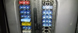
There is also at least one main fuse. Often the main and power fuses are installed closer to the battery. See this fuse box diagram.
Modern cars have at least two fuse boxes. In most cars, one fuse box is located under the hood and the other is located inside the car.
When any electrical device in your car is not working, the first step is to check the fuse that protects the circuit to that device.
You can find the fuse map in your owner's manual or on the fuse box cover. Many vehicles have a fuse puller, which may be located in the fuse box or in the fuse box cover.
Fuse Standards
Historically, the mechanical design of housings and their overall and connecting dimensions are different in one country or another. There are four main national standards for fuse mounting sizes: North American, German, British and French. There are also a number of fuse housings that are the same from country to country and are not national standards. Most often, such cases refer to the standards of the manufacturer that developed a specific type of device, which turned out to be successful and gained a foothold in the market. In recent decades, as part of the globalization of the economy, manufacturers have gradually joined the international system of fuse housing standards to simplify the conditions for the interchangeability of devices. When designing new equipment, efforts should be made to use fuses of international standards: IEC 60127, IEC 60269, IEC 60282, IEC 60470, IEC60549 and IEC 60644.
When servicing equipment in use, depending on the country where it was manufactured, you may encounter fuses that comply with national standards. Most often, similar devices are also available in the nomenclature regulated by international standards, but in doubtful cases when replacing, additional identification of the device is always desirable.
Despite the fact that fuses are historically the first elements of protective circuits and have been used in electrical engineering for more than a hundred years, they have not become an “endangered species”, as some experts predicted in the 30s–50s of the last century, when the industrial introduction of circuit breakers began , on the contrary, have significantly expanded the scope of their application, being a reliable means of protection in emergency situations and, in fact, the “last frontier” in the protection of expensive and complex power electronic systems.
In preparing the article, information materials from the following fuse manufacturers were used: Siba, Cooper Bussmann, Ferraz-Shawmut, General Electric, Eaton, as well as the following Internet resources:
- Official website of the International Electrotechnical Commission.
- Official website of Underwriter Laboratories (UL).
- Official website of SIBA.
- Official website of Cooper Bussmann.
- Official website of General Electric (energy section).
- Eaton official website.
- Ferraz-Shawmut official website.
Literature
- Chebovsky O. G. et al. Power semiconductor devices. Directory. 2nd ed. M.: Energoatomizdat, 1985.
- Sicherungseinsätze für kombinierten Halbleiter - und Leitungsschutz Dipl.-Ing. Thorsten Falkenberg, Technischer Projektleiter im Bereich Halbleiterschutz, SIBA LLC.
Integrity check
There are several ways to check fuses. The easiest way is to remove the fuse and check it visually.
For example, we are going to check the cigarette lighter fuse. Stopped working. Most likely this is due to the fuse, which blows most often.
Turn the ignition key to the OFF position. Before removing a fuse, it's always a good idea to mark its position so you can put it back in the same place.
We take a puller and pull out the fuse. Fuses have a thin metal wire that melts when the current exceeds the fuse's rating. This blown fuse has a melted conductor, see photo.
If the fuse is blown, something has shorted the protected circuit. If the problem persists, the fuse will blow again. In this car it was a small screw that fell into the cigarette lighter socket.
Spare fuses may be located inside the fuse box cover. When replacing, only use a fuse of the correct type and current rating. The cigarette lighter fuse is 15 amp, blue in most cars.
Some types of fuses, such as the miniature low-profile fuses pictured above, are universal and can be purchased at any auto parts store. Large fuses or panels with multiple fuses can be ordered from specialist auto shops or your dealer.
Analytical calculation of the time-current characteristics of the fuse
Content
1. Basic information from the theory………………………………………………………………. 3
2. Analytical calculation of the time-current characteristics of fuse 5
3. Results of experimental studies of the fuse on a laboratory bench …………………………………………………………………………………………………………………. 7
References………………………………………………………………………………………… 8
Basic information from the theory
A fuse is a protective switching electrical device designed to disconnect the circuit it protects by destroying specially designed live parts under the influence of a current exceeding a certain value for a certain time.
The fuse protects consumers from currents of significant long-term overloads and short circuits.
Its main characteristic is the time-current characteristic, showing how long it will take for the fuse to trip at a given emergency current (Figure 1).
The time-current characteristic of a fuse, even with an intact fuse link (no corrosion or deformation), is not stationary in the current-time axes. Its position depends on the temperature (the characteristics of the fuse obtained when it is heated by the emergency current from the heated state differ by 25...45% from the characteristics that the manufacturer indicates for the conditions of heating the fuse by the emergency current from the “cold” state).
The fuse, protecting the consumer, directly breaks the power electrical circuit through which electricity flows from the power source to the load and, thus, is an electrical device of primary switching, direct action.
Among devices up to 1000 V, only automatic switches have an equivalent switching capacity (the ability to turn off all types of currents in emergency and abnormal operating modes, including short-circuit currents), and circuit breakers for voltages above 1000 V. At the same time, the functionality of circuit breakers and switches is higher. The fuse is superior to these devices only due to its lower cost and, in some cases, better weight, size and speed.
Some fuses are current-limiting electrical devices. This means that their response time in emergency mode is less than the time required for the short circuit current (SC) to reach its maximum (impact) value. In other words, the current-limiting fuse trips faster than the short-circuit current reaches its maximum value.
In laboratory work, only general purpose fuses (hereinafter referred to as fuses), which are the most common type of fuses, will be tested.
Any fuse consists of the following main parts:
· fuse link;
· fuse body;
· body filler;
· connecting contacts of the fuse link;
In addition, the fuse (usually a fast-acting one) may include:
· operation indicator;
· striker for influencing external devices (indicators) or for
impact on fuse output contacts;
· output contacts.
The selection of fuses is made:
· According to the compliance of the fuse insulation with the network voltage at the point of their installation;
· According to the permissible heating of fuses in long-term operation;
· By failure of fuses in the event of a calculated short-term overload (for example, starting an engine);
· According to the correspondence of the time-current characteristics of the fuses to the design conditions of the protected circuit.
Analytical calculation of the time-current characteristics of the fuse
Under normal conditions (i.e., at a current not exceeding the rated current), the operating point of the fuse-link is located in the steady-state portion of the heating curve. In this case, all the energy transferred to the fuse link in the form of heat is released into the environment.
The current at which a fuse-link can operate for a long time without melting is called the rated current of the fuse-link Iн
.
The current at which the fuse-link burns out no earlier than after one hour is called the boundary current I
etc. Depending on the material of the fuse-link, the boundary current may be 10-70% higher than the rated current.
The process of fuse tripping during a short circuit or long-term overload is divided into several stages: heating the insert to the melting temperature, melting and evaporation of the insert, the occurrence and extinguishing of an electric arc.
The way a fuse-link behaves when the current in the circuit changes is described by its time-current characteristic.
It is quite difficult to accurately calculate this characteristic due to the need to take into account many different factors, however, there is a simplified calculation algorithm that has an acceptable error and is used when performing laboratory work.
For a round fuse-link, the relationship between its diameter and the fusing current can be expressed by the empirical relationship
,
where
d=
0.41mm, is the diameter of the fuse link;
A0
is a constant equal to 60 for copper.
The rated current of the fuse link can be obtained from the expression
, where KI is a coefficient equal to 1.6 - 2.0 for copper. Select the value 1.6.
The response time of the fuse can be determined from the assumption that the heating nature of the fuse-link is adiabatic, i.e. all the heat generated in the fuse-link is spent on heating it. This condition is already met at currents exceeding 3.5 I
n.
The formula for determining the response time of an open fuse-link has the form
where K2=1.2-1.3 is a coefficient that takes into account the duration of extinguishing the electric arc, we take the value 1.2; S
- cross-section of the fuse-link, mm2; I-current, A;
A ' and A“ are constants taken depending on the material of the fuse link,
,
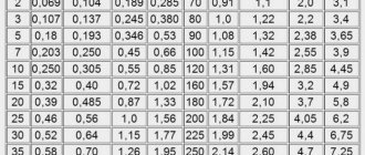
The results of calculating the analytical time-current characteristics of the fuse are summarized in Table 1.
Table 1—Results of calculating the analytical time-current characteristics of the fuse link.
| Current ratio | In | 3.5In | 5In | 7In | 10In | 12In |
| Current, A | 9,845 | 34,457 | 49,225 | 68,92 | 98,45 | 118,14 |
| Response time, s | ∞ | 1,48 | 0,72 | 0,37 | 0,18 | 0,13 |
The calculated time-current characteristic is given in paragraph 3.
How to check the main fuse
All cars have at least one main fuse. It is usually installed on the positive terminal of the battery or in the fuse box connected to the positive battery cable.
Often the main fuse will blow if you accidentally touch the wrong battery terminal while charging a dead battery. A sign of a blown main fuse is a lack of power and lighting inside the car.
Checking the main fuse is easy and you can usually see if it's blown. If the main fuse has blown, chances are that several other smaller fuses have also blown.
How to Test a Fuse Using a Multimeter
If you have a multimeter, then there are two ways to check the fuse.
Voltage check
The first way is to measure the voltage at both contacts (terminals) of the fuse. Small fuses have the top of both terminals protruding through the fuse body. This allows you to measure the voltage on each side of the fuse without removing it.
Set the multimeter to DC voltage measurement mode (=U). Connect the COM probe (black) to the negative or metal part of the body. Set the parking brake and turn the ignition to the ON position.
The ignition must be on, because when the ignition is off, not all fuses are supplied with voltage. Using the positive test lead (red), check the voltage on both sides of each fuse. A fuse is simply an electrical conductor.
If both sides show 12 volts, the fuse is good.
If there is 12V on one side of the fuse and no voltage on the other side, the fuse has blown.
This method works well when many fuses need to be tested at the same time.
Resistance check
If you have already pulled out the fuse but it is not clear whether it is blown or not, you can check its resistance. Resistance is inversely proportional to current. The lower the resistance, the higher the current.
Resistance is measured in Ohms. A conductor, like copper or aluminum wire, has a very low resistance (about 0 ohms). A good fuse will show 0 (or close to 0) ohms.
In other words, there must be continuity between the two contacts of the fuse. A blown fuse will show very high resistance (infinity).
To measure the resistance of any electrical equipment, it must be disconnected from the electrical circuit. You cannot measure resistance while the equipment is connected or turned on. Switch the multimeter to “Ohm” and connect the probes as in the photo.
If the fuse is blown, the multimeter shows OL, which means there is no continuity or the resistance is higher than can be measured. If the fuse is good, the multimeter shows 0 ohms.
Watch the video on how to check the fuse using a lighter or multimeter:
What can cause a fuse to blow?
A fuse protects a circuit from higher current than the circuit can handle. If the fuse is blown, it means there is a short circuit somewhere. It can be between two wires or the power wire and ground (car body).
A fuse can also blow if the equipment draws more current than it is designed to handle. For example, if the windshield wiper or fan motor is blocked when turned on, it will draw higher current and possibly blow a fuse.
The same thing can happen if the winding inside the motor is shorted. There are several common problems that cause fuses to blow in many cars:
Source