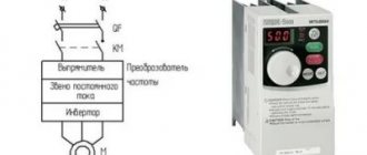
Each of us roughly understands why a fuse is needed and how to choose it. We've all been angry or frustrated by a blown fuse. Sometimes we wish our circuits didn't have such a component. With the advent of electrical distribution in the 1800s, fuse links became an important means of preventing fires. Electronic systems need them for the same reason, plus fuses protect expensive electrical system components. Electronic systems have the same fire problems as electrical ones.
Some mechanic coined the phrase: “A twenty-dollar transistor will always burn out to protect a ten-cent fuse.” The fuse is not intended to protect the transistor . It would be even less suitable for protecting a laser diode, since the fuse links are destroyed by a few nanoseconds of overcurrent.
Fuses are ideal for protecting wires and circuit board traces from melting and burning. This can happen when contacts occur between wires due to damaged insulation or a magnetic wire that is shorted due to vibration and contractions due to an alternating magnetic field. Another common fault is with electrolytic and tantalum capacitors, which can fail if shorted.
Instead of relying on a fuse link to protect your product's electronic components, you can power the circuit you're designing from a lab power supply and set a limit on the output current. You can set the power supply current to less than what would melt the wires or destroy the pn junctions inside the transistor or IC. Then your test circuit will simply heat up (in case of incorrect assembly or calculation error) rather than explode. Once everything is working, you can add a fuse.
Need for a fuse
Anything powered by a source with low internal resistance needs a fuse. This could be an electrical appliance that plugs into an outlet or is powered by a battery, or that runs off the alternator in your car. A low impedance source can provide enough current to melt conductive parts and start a fire (picture below). Insurance company laboratories were created to reduce the likelihood of a fire and, as a result, prevent insurance claims. The fuse can protect people from a short circuit to the frame, and also protect the electrical appliance from fire.
Select fuse package
Your application will determine the type of fuse you will use. You may need a high voltage fuse. If your product is primarily sold in the US, then a standard of typically 1/4 inch (3.5 cm) is appropriate. In Europe, the 5 × 20 mm glass fuse is more common. For automotive applications, blade-lead fuses are used throughout the world. In industrial electrical cabinets you can see the industrial type of fuses. If you are protecting PCB traces, surface mount fuses are ideal (picture below).
It's often a simple matter of looking at products similar to yours to see what fuse they used. This can significantly help you make your choice.
Estimation of fuse response speed
Once you have selected your fuse package, perhaps part of this effort is to ensure that the fuse link's tripping speed meets the requirements of your application. A fast-blow fuse will burn quickly before the wires or traces on the circuit board have time to heat up. However, rapid burnout can cause a nasty crash due to momentary overload.
Incandescent lamps, capacitive loads, and linear and switching power supplies have a large current pulse when turned on. The problem is a little more complicated for AC-powered loads, since the AC inrush at turn-on may be less severe if the turn-on timing coincides with the voltage zero crossing. You must also consider the condition when you connect the power at the moment of the voltage peak value. This will create a short but significant current pulse that can burn the fuse-link.
Conditions for selecting a fuse
Date added: 2015-07-23; ; Copyright infringement
Fuses are selected according to the following conditions:
3.1. According to rated voltage. Rated voltage of fuses Upp.nom. should generally be equal to the rated voltage of the electrical installation
3.2. According to the rated current of the fuse link. Rated current of fuse link Ipv.nom. must be selected according to the following conditions:
where: Iр.max. – maximum operating current of the network, protected by a fuse;
Imax. – maximum network current when turning on electrical receivers whose starting currents significantly exceed the rated ones;
Kn· – reliability factor accepted for lines supplying incandescent lamps and heating devices 1.0; fluorescent lamps – 1.25; DRL lamps – 1.1.
α is a coefficient depending on the starting mode of the protected electric motors and the type of fuse.
When protecting a line to which one motor is connected
where Ki is the multiplicity of the motor starting current.
When fusing a line to which several receivers are connected:
where Ko is the simultaneity coefficient;
– the sum of the operating currents of all receivers except one, for which the difference between the starting and rated currents is the greatest
Istart. – starting current of the motor excluded from the sum.
When selecting fuse links of instantaneous fuses (PN, NPN, NPR) to protect short-circuited electric motors with soft starting conditions (starting duration 2.5 s) α = 2.5; with heavy starting mode α = 1.6; for low-inertia fuses (PR-2) with easy starting mode α = 3.0; for severe α = 2.0; with frequent starts (15 or more per hour) of engines with light starting mode, fuse links must be selected as for heavy duty.
Fuses selected according to these conditions protect squirrel-cage motors only against short circuits.
The fuse current of the PKT-10 kV fuse to protect transformers is selected according to 3 conditions:
1) when detuned from the operating maximum current
where Kn = 1.25 – reliability coefficient;
2) when detuning from the inrush current of the magnetizing current of the transformer when it is turned on under voltage
3) when detuning from short-term current when starting large electric motors.
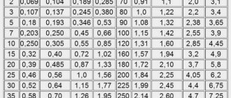
If these calculations are not made, the values of the fuse-link currents are selected according to the power of the transformers according to table. 18.8 [2] (at Unom. = 10 kV).
| St.nom. kVA |
| Ipv.nom., A |
3.3. By selectivity of protection.
To check the selectivity of the action of fuses, as well as to coordinate them with the operation of relay protection, selectivity maps are drawn up. When installing fuses of the same type with a voltage of up to 1000 V, selectivity will be observed if the fuse links of each two fuses connected in series differ by at least two steps on the scale of rated currents of the fuse links, and of high-voltage fuses with quartz filler - by one step. Technical data of fuses up to 1000 V are given in table. 5.2. and in Fig. 5.1, 5.2., p. 28-30 [2], and above 1000 V s, 206-210 [2].
Fuse current reserve
When developing an ultraviolet eraser for UVPROM wafers in a semiconductor machine, the following situation arose. It is known that if the fuse link worked, it meant serious equipment failure. Everything should work well. But the mistake was that the fuse-link operating current was set too close to the expected load of the high-voltage linear transformer.
This system worked well in the laboratory, but when the machine was put into real production running on 50 Hz AC power, nuances emerged. They were associated with a lower frequency, which resulted in greater losses in the transformer and it drew more current. The current reserve turned out to be too small, which led to almost instantaneous fuse blowing. Fortunately, European 5x20 mm fuses were used, so replacing them with more powerful ones was not difficult.
Instead of installing more powerful fuses directly on the printed circuit board, management decided to place them on holders in a separate box. This significantly complicated the installation of the circuit and added additional costs for materials, but the speed of fuse replacement thus increased. It is difficult to say now who was right in this situation, the developer or the manager.
Also, do not forget about the starting characteristics of the electrical equipment for which the fuse is selected. After all, if you choose a fuse-link designed for the maximum current of the device, but according to the starting characteristics this maximum current will never be used in the operating cycle, you should not choose a fuse for the maximum current. Research the duty cycle of the device and make your equipment selection based on it.
All this is to say that you should select a fuse based on the fact that it will blow at a calculated overload, and not just 10% higher than the operating current. Measure operating current under any operating conditions and at any temperature, if necessary. Understand that any DC bus power system will have a large inrush current when first turned on. The fuse should be able to withstand this even if a child flips the switch several times within a few seconds.
It is possible that your fuse current rating will double or even 10 times the operating current after calculations and testing. Your job is to eliminate false tripping of the fuse link, while making sure that any fault or short circuit will blow the fuse before a fire starts. As noted above, you can try a slow-blow fuse to get around the inrush current problem while still protecting the circuit from fire.
Fuses
When operational (technological) overloads and emergency modes occur as a result of circuit malfunctions, currents flow through the electrical circuits of the emergency circuit in excess of the rated values for which the electrical equipment is designed.
As a result of exposure to emergency currents
and
overheating of current conductors
, electrical insulation is damaged, contact surfaces of connecting busbars and electrical devices burn and melt. Electrodynamic shocks during transient processes cause damage to busbars, insulators and reactor windings.
To limit the amplitude of emergency currents and the duration of their flow, special devices and systems for protecting electrical equipment are used.
Note. Protection devices must turn off the emergency circuit before its individual elements fail.
In case of large overloads or short circuits, the protection devices must immediately turn off the entire electrical installation or part of it with maximum speed to ensure further operation or, if the accident is a consequence of the failure of one of the circuit elements, prevent the failure of other electrical equipment.
conclusions
To keep your circuit from melting and catching fire, it never hurts to install a fuse at the input. For large electrolytic capacitors in some inexpensive consumer products, the current-carrying traces on the circuit boards are smaller, so that when the capacitor shorts, the traces on the circuit board melt, serving as a fuse. However, this is not the best solution since copper has a high temperature coefficient and the PCB manufacturing process does not control the needs of your temporary copper fuse.
You're better off installing small surface mount fuses that operate more predictably. This way, when a technician replaces "broken" electrolytic capacitors, he or she can solder a new fuse. With fast delivery, capacitors and fuses can be ordered during lunch and will arrive at 10:00am the next day. Better yet, there will be no traces of molten metal on the printed circuit board (PCB). If they are repaired with a bus wire, the melting current will be too high, and the product may ignite the next time the electrolytic capacitor breaks down.
Selecting a fuse to protect motors
Asynchronous motors have an unpleasant feature - their starting current is 5-7 times the rated current of the motor! Fuses are not selected according to the motor rating!
This selection is valid for “ slow-blow” or “ gL ” fuses (VDE 0636).
The rated current of a fuse is limited by its heating capacity. When this current passes through the fuse for a long time, the fuse body does not overheat. The rated current of the fuse must be no less than the maximum rated current of the fuse link used with this fuse.
The rated currents of the fuse and fuse link / in must not be less than the rated current of the circuit.
The main condition determining the choice of fuses for protecting squirrel-cage asynchronous motors is detuning from the starting current.
The rated current of the fuse should be approximately 2.5 times less than the starting current or 1.6 - 2.8 times the rated current. But even when protecting wound-rotor motors, when the fuse can be selected for a current close to the rated one; such protection is less sensitive to small overloads than thermal relays. Therefore, it is more advisable to use thermal relays to fully protect the engine.
The selection of fuse links from starting currents is performed based on time: the start of the electric motor must be completed before the insert melts under the influence of the starting current.
Operating experience has established a rule: for reliable operation of inserts, the starting current should not exceed half the current, which can melt the insert during the start-up.
Selection of fuses to protect asynchronous electric motors:
All electric motors are divided into two groups according to start time and frequency
Motors with easy starting are considered to be motors of fans, pumps, metal-cutting machines, etc., the start of which ends in 3...5 s; these motors are started rarely, less than 15 times per 1 hour.
Engines with heavy starting include engines of cranes, centrifuges, ball mills, the start of which lasts more than 10 s, as well as engines that are started very often - more than 15 times per hour. This category also includes engines with easier starting conditions, but especially responsible ones, for whom false burnout of the insert during startup is completely unacceptable.
The selection of the rated current of the fuse link for detuning from the starting current is made according to the expression: Ivs ≥ Ipd / K (1)
where Ipd is the starting current of the motor, determined from the passport, catalogs or direct measurement; K is a coefficient determined by the starting conditions and is equal to 2.5 for engines with easy starting, and 1.6...2 for engines with heavy starting.
Since the insert heats up and oxidizes when starting the engine, the cross-section of the insert decreases, the condition of the contacts deteriorates, and it can falsely burn out during normal engine operation. An insert selected in accordance with formula 1 may also burn out if the engine starts or self-starts are delayed compared to the estimated time. Therefore, in all cases, it is advisable to measure the voltage at the motor inputs at the time of start-up and determine the start-up time.
The rated current of the fuse indicated on it is equal to the highest rated current of the fuse links intended for this fuse design. The rated current of the fuse must be greater than the effective value of the current flowing through it in normal operating mode.
To prevent the inserts from burning out during start-up, which may result in engine operation in two phases and damage, it is advisable in all cases where this is permissible due to sensitivity to short-circuit currents, to select inserts that are coarser than according to condition (1).
Each engine must be protected by its own separate protection device. A common device is allowed to protect several low-power motors only if the thermal stability of the starting devices and overload protection devices installed in the circuit of each motor is ensured.