A current limiter (CU) is a device used in electrical or electronic circuits to reduce the upper limit of direct (DC) or alternating (AC) current supplied to a load. This ensures timely and reliable protection of generation circuits or electronic systems from harmful effects due to a short circuit in the network or other negative processes leading to a sharp increase in AC/DC.
Limiting techniques are used to control the amount of current flowing in a DC or AC circuit. The device guarantees that if its size limit is exceeded, the protection will operate reliably and in a timely manner. Current-limiting devices can be used in various modifications depending on sensitivity, standard current load, response time and possible causes of a short circuit in the network.
Excess AC/DC can occur internally due to shorted components such as diodes, transistors, capacitors or transformers, as well as external problems such as network overload, short circuit or overvoltage at the input power terminals.
Types of limiting devices
The choice of protective devices depends on several factors. Devices can be passive or active, and can be used individually or in combination. Typically the limiter is connected in series with the load.
Types of limiting devices:
- Fuses and resistors. They are used for simple current limiting. A fuse usually blows if its AC/DC exceeds its rated size. Resistors are integrated into the circuit design. The correct resistance value can also be calculated using Ohm's law I = V / R (where I is current, V is voltage and R is resistance). There are a large number of different fuses on the electrical market that can meet any power dissipation need.
- Circuit breakers. They are used to cut off power, just like a fuse, but their response is slower and may not work on particularly sensitive circuits in expensive equipment.
- Thermistors. Negative temperature coefficient (NTC) thermistors are used to limit the initial surge currents that flow when the device is connected to the mains power. Thermistors have high resistance when cold and low resistance at high temperatures. NTC limits the inrush current instantly.
- Transistors and diodes. Regulated power supplies use limiting circuits such as integrated circuits, transistors, and diodes. Active circuits are suitable for sensitive networks and operate, reducing the load or turning off the power, to a damaged short circuit or to the entire network.
- Current limiting diodes are used to limit or regulate over a wide range of voltages. A two-terminal OT device consists of a gate shorted to a source. It maintains DC regardless of voltage changes.
Bipolar transistor limiter
The main disadvantage of the scheme described above is the difficulty of changing the limit limits. In more advanced devices, to eliminate this drawback, an additional element is used that performs the functions of a sensor. As a rule, such a sensor is a powerful resistor that is connected in series with the load. At the moment when the voltage drop across the resistor reaches a certain value, the current will automatically be limited. The diagram of such a device is shown in Figure 2.
Load current limiter in electrical networks
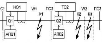
Power distribution systems have circuit breakers to turn off the power in the event of a fault. They have certain disadvantages in ensuring the necessary reliability, since they cannot always disconnect the minimum required emergency section of the network for repairs. The problem arises when renovating the power supply by adding new power or cross-connections, which must have their busbars and breakers upgraded to higher short-circuit current (FCC) limits.
Improving the quality of electricity in networks directly depends on the reliability of the operating mode of network equipment. Among the various types of interference that affect the quality of voltage in the network (surges, harmonic distortion, etc.), the most serious obstacle is voltage drops, since the associated phase angle surges can lead to equipment breakdown, a complete shutdown of production, facilities Housing and communal services, which with the speed of a chain reaction will create a threat to the livelihoods of the population.
A common cause of voltage drop is short circuit current. When a fault occurs in the distribution network, the voltage drops sharply on all damaged buses. The level depends on the connection point and the electrical distance of the bus to the accident site.
To reduce negative processes and disconnect faulty sections of the network, the following limiters are used:
- Distribution static compensator;
- dynamic voltage recuperator;
- thyristor-controlled capacitor;
- semiconductor static transfer switch;
- solid state fault current limiter.
Such protective devices are not always perfect. Some have the disadvantage of high cost, and others can limit the fault current to less than 5 times the normal current, which is insufficient for overloads.
Points of application of current limiters in electrical power equipment:
- To the point of operation of the main switch on the emergency feeder of consumer loads with the inadmissibility of interruptions in power supply;
- on equipment whose performance characteristics no longer correspond to the maximum short-circuit current, which has increased due to an emergency in power supply systems.
A simple solution to OT in power supply equipment is to add a resistor to the circuit. This limits the rate at which the TSC can increase before the breaker opens, but it also limits the circuit's ability to meet rapidly changing customer demand, so adding or removing large loads causes unstable power.
CURRENT LIMITER
CURRENT LIMITER
The disadvantage of fuses is their disposability and the need for subsequent manual replacement with another fuse designed for the same current. When there is no suitable one at hand, they use fuses for a different current or install homemade fuses or simply wire jumpers, which negatively affects the reliability of the equipment. You can ensure automatic protection of the device and at the same time increase performance by using an electronic fuse. We often neglect protection, and as a result we have many burnt-out circuits due to incorrect connection to the power supply, accidental short circuit, excess load current, etc. So spend a little time and supplement any power supply with a voltage of 3 - 25 V with this protection. It can be built into a power supply or charger.
The load current limiter contains conventional bipolar transistors. The input voltage through resistor R1 goes to the base of transistor VT1 and opens it. The transistor operates in saturation mode, so the input voltage is supplied to the output of the power supply. When the current is less than the threshold, transistor VT2 is closed and the LED does not light up. Resistor R3 acts as a current sensor. As soon as the voltage drop across it exceeds the opening threshold of transistor VT2, it will open, the LED will turn on, and transistor VT1 will begin to close, and the current through the load will be limited.
Source
Application of current protection in electronic circuits
The inrush current occurs when the switch supplies voltage. This is because the difference between the equivalent series resistance of the capacitor and the line resistance is only a few milliparts and results in a large inrush current. Four factors that can influence this process:
- AC input current value.
- Minimum resistance required by the NTC thermistor (at t = 0).
- Constant DC.
- Ambient temperature.
A current limiter is a device or group of devices used to protect circuit elements from inrush loads. Thermistors and negative temperature coefficient (NTC) resistors are 2 simple protection options. Their main disadvantages are long cooling times and high power dissipation. A current limiting diode regulates or limits current over a wide range. They consist of a JFET with a gate shorted to the source and functioning as a two-terminal current limiter.
They allow the current passing through them to rise to a certain value and compare with a given value. Unlike Zener diodes , they store a constant current rather than a voltage. Current-limiting diodes keep the current flowing through them constant regardless of any change in load.
Electronic limiters
Much more advanced than the fuses mentioned above are electronic limiters. Conventionally, such devices can be divided into two types:
- restored automatically after the fault has been eliminated;
- restored manually. For example: the limiter circuit has a button, pressing which causes it to restart.
Separately, it is worth mentioning the so-called passive protection devices. Such devices are designed for light and/or sound signaling in situations where the permissible current in the load is exceeded. For the most part, such alarm schemes are used in conjunction with electronic limiters.
Prices for current limiters
Types of Current Limiting Diodes
There are many different types of current limiting diodes, classified by:
- rated current of the regulator;
- maximum ultimate voltage;
- operating voltage;
- power consumption.
The most common values for the maximum usable voltage are 1.7 V, 2.8 V, 3.1 V, 3.5 V, and 3.7 V and 4.5 V. The regulator current rating can range from 0.31 mA to 10 mA, with the commonly used regulator current being 10 mA.
DC current limiting circuit
Most power supplies have separate DC and voltage control loops to regulate their outputs in either constant voltage (CV) or constant current (CC) mode, which are brought into control depending on how the load impedance matches the output voltage and current settings.
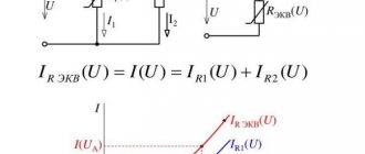
Thus, protection is carried out mainly by limiting the current value. In this case, you can use a simple source limiter circuit using two diodes and a resistor. With any power supply, there is always a risk that the output will short circuit. Accordingly, under these conditions it is necessary to protect it from damage. There are a number of circuits that can be used to protect power supplies.
One of the simplest circuits includes only two diodes and an additional resistor. The circuit uses a resistor to measure noise, placed in series with the output transistor. Two diodes located between the circuit output and the transistor base provide protection. When the circuit is operating within its normal operating range, there is a small voltage across the resistor. This voltage plus the transistor's base emissive voltage is much less than the diode junction drop required to turn on the two diodes. However, as DC increases, the voltage across the resistor increases. When it is equal to the voltage required for operation, they turn on, the transistor voltage drops, thereby limiting the current.
The circuit of this diode current limiter for power supply is simple. The value of the series resistor can be calculated so that the voltage across it increases to 0.6 volts (the turn-on voltage for a silicon diode) when maximum current is reached. However, it is always better to ensure that there is some margin of protection, and it is best to limit it to the required level.
Limiter with feedback
The same simple diode form of current limiting can be included in power circuits that use feedback to determine the actual output voltage and provide a more precisely regulated output. If the output voltage measurement point is taken after the series current resistor , then the voltage drop can be corrected at the output.
This circuit provides much better regulation than a direct emitter regulator and can also account for the voltage drop across the current limit resistor if there is sufficient voltage drop across the transistor in the power supply circuit. The output voltage can also be adjusted to the desired value using a variable resistor. The diode form of current limiting can be easily integrated into the power supply circuit. Moreover, it is cheap and convenient.
Features of different current limiters
Each type of device, by limitation, is developed for specific tasks and has certain properties:
- fuse - has fast action, but requires replacement;
- reactors - effectively resist short-circuit currents, but have significant losses and voltage drop across them;
- electronic circuits and high-speed switches - have low losses, but weakly protect against shock currents;
- electromagnetic relays - consist of moving contacts that wear out over time.
Therefore, when choosing which circuit to use for yourself, it is necessary to study the whole range of factors characteristic of a particular electrical circuit.
Application areas of current-limiting diodes
Current-limiting diodes provide superior performance and ease of operation compared to bipolar transistors in protection systems. They are versatile and have excellent performance against dynamic temperature drift. Devices using diodes:
- signal generator circuits;
- synchronization circuits;
- charging device;
- LED control;
- replacement of holding coils in telephone communication devices.
Current limiting diodes are available from many global semiconductor manufacturers such as Calogic, Central Semiconductor, Diodes Inc., ON Semiconductor or Zetex. The electronics market has a very wide selection of diodes, diode circuits used, or any other devices that may require current limiting.
Infineon IRF9540N
V. I. Ivolgin, Tambov
Any electronic device has a power source, due to the energy of which it performs its functions. And it is not surprising that significant space in the press is devoted to their descriptions, design recommendations, consideration of the operation of individual components, and proposals for their improvement.
It should be noted that modern power supplies, as a rule, have a fairly low output impedance. And for this reason, in emergency situations, even at low voltages at their output, significant current overloads cannot be ruled out, leading to damage to the source or the device itself. In this regard, power supplies are usually equipped with protection systems. They are quite diverse and have more or less autonomy relative to the design of the source itself.
One of the options for such a device, which can be used as an independent unit, is proposed in [1]. Its operating principle is based on limiting the current consumption, the sensor of which is a low-resistance resistor connected in series to one of the wires between the power source and the load. The voltage from the sensor, proportional to the current consumed, after amplification, is used to control the pass transistor. By changing its operating mode at the right time, direct overload protection is performed.
In this article, a well-known structure based on two bipolar transistors is given as a prototype (Figure 1). The main disadvantage of the device is the significant voltage drop across it, which reaches its maximum value at the maximum operating current. According to the author, it is approximately 1.6 V, and about 1 V drops on the pass transistor VT1, and the remaining 0.6 V on the current sensor Rs. In connection with this, the author proposes another circuit that allows reducing the voltage drop across it to 0.235 V at limiting current is 1.3 A. This value is quite small, although it is achieved by using a more complex circuit containing about 20 elements [1].
| Picture 1. | Schematic diagram of a prototype current limiter. | |
On the other hand, this design, in comparison with the one proposed by the author, is attractive in its simplicity. And in this regard, the question arises: is it possible, while remaining within such a simple structure, to achieve a reduction in the voltage drop across such a fuse without noticeably complicating it? And how?
As follows from the given numerical data for the prototype, the largest voltage drop occurs across the pass-through bipolar transistor VT1. Analysis shows that with such a switch on, it is impossible to achieve its saturation, and thereby achieve low voltage drop values, without an additional power source. But introducing it only for this purpose would be expensive. And although it would probably be possible to propose some other ways to reduce these losses on VT1, it would be more rational to immediately replace the bipolar transistor with a field-effect transistor with a low channel resistance value. This will reduce both the voltage drop across the control transistor and the limiter’s own consumption by reducing control currents. In addition, it is advisable to change the connections between the transistors so as to convert the limiter into a system of two amplifier stages, instead of just one in the original structure. Ultimately, the circuit diagram of the limiter under study will look like this (Figure 2), which can also be considered as a simplified version of the device given in [2].