Procedure for studying drawings
How to read electrical diagrams correctly and understand the information presented on the drawing? It is enough to be able to navigate the graphical symbols of GOST; this is the basis of each developed project.
First, determine the type of drawing. According to GOST 2.702-75, each graphic document has an individual code. All electrical drawings have the letter “E” and a corresponding digital value from 0 to 7. The electrical circuit diagram corresponds to the code “E3”.
Reading the circuit diagram:
- Visually familiarize yourself with the presented drawing, pay attention to the specified notes and technical requirements.
- Find on the schematic diagram all the components indicated in the list of the document;
- Determine the power source of the system and the type of current (single-phase, three-phase);
- Find the main components and determine their power source;
- Familiarize yourself with protection elements and devices;
- Study the management method indicated on the document, its tasks and algorithm of actions. Understand the sequence of actions of the device when starting, stopping, short circuit;
- Analyze the operation of each section of the circuit, determine the main components, auxiliary elements, study the technical documentation of the listed parts;
- Based on the studied document data, draw a conclusion about the processes occurring in each link of the chain presented in the drawing.
Knowing the sequence of actions, alphabetic symbols, you can read any electrical circuit.
Conventionally graphic symbols in electrical circuits GOST
There are complete and linear circuit diagrams.
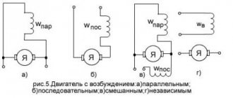
Antennas, ultra-high-frequency elements, couplers, short-circuiters, valves, phase shifters, transformers have the symbol W.
Conventional graphic symbols of power equipment of stations and substations
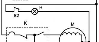
A distinction should be made in the image of the contact and the thermal relay contact, depicted as follows: M is the letter designation for DC and AC motors. This standard does not establish conventional graphic symbols on railway signaling, centralization and interlocking diagrams. If the symbols on various electrical circuits of GOST contain elements that do not have information about sizes, then these components are made in sizes corresponding to the standard image of the UGO of the entire circuit.
Given such circumstances, designers adopt practical experience from more experienced colleagues; they simply know how to do many things correctly, but do not know why.
Otherwise, due to the inattention of the engineer, the risk of purchasing inappropriate or more expensive equipment increases.
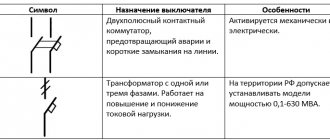
Designations of switches on diagrams
The designation of a three-pole switch on a single-line diagram has fundamental differences from single-pole models. It is driven mechanically or electrically. Types of contactors The figure shows a two-contact switch. C - display of the coil of a device with mechanical interlock.
The letter B on electrical circuits represents converters of non-electrical quantities into electrical ones: microphones, photocells, thermal sensors, piezoelectric elements, pressure sensors, speed sensors, sound pickups, detectors.
Sign for designating mobile contacts Functions of parts with fixed contacts Designations of power supply elements on single-line diagrams show only power elements. Their combination according to a special system, which is provided by the standard, makes it possible to easily depict everything that is required: various electrical devices, instruments, electrical machines, mechanical and electrical connection lines, types of winding connections, type of current, nature and methods of regulation, etc.
If the symbols on various electrical circuits of GOST contain elements that do not have information about sizes, then these components are made in sizes corresponding to the standard image of the UGO of the entire circuit.
Having dealt with the electrical circuits, we can move on to the designations of the elements indicated on them. UGO lamps of electrical circuit diagrams. Designations on electrical circuit diagrams depict connectors, fuses, terminals, and containers.
General rules for constructing contact designations 1. Image of a circuit breaker on a complete diagram Contact switching device. UGO in single-line and complete electrical circuits For these circuits, there are several groups of symbols, we present the most common of them. Wiring diagrams and markings of electrical circuits
The most popular documents in the section
A distinction should be made in the representation of the contact and the thermal relay contact, depicted as follows
C is a symbol of alternating and direct voltage, used in cases where the device can be powered from any of these sources. In addition, in the conventional graphic symbols on electrical circuit diagrams, special symbols are additionally used to explain the operating features of a particular circuit element. For the contactor, the opposite happens.
For example, a fuse and a resistor have minor differences. If they are absent, then this means a non-contact intersection of conductors. Examples of constructing designations for multi-position switching devices are given in Table. B - DC commutator motors: 1 - with winding excitation from a permanent magnet 2 - Electric machine with excitation coil In conjunction with electric motors, the diagrams show magnetic starters, soft start devices, and a frequency converter. The initial state of the circuit breaker is when the elements are closed.
To describe the main functions of nodes, the rectangles displaying them are signed with standard letter designations. For example, there are several equivalent options for designating switching contacts, as well as several standard designations for transformer windings. In this article, we will look at the symbols in electrical diagrams: what types there are, where to find the decoding if it is not indicated in the project, how this or that element on the diagram should be correctly designated and labeled. Designation of communication lines on GOST 2 circuit diagrams.
Home Electrical wiring Conventional graphic symbols Conventional graphic symbols UGO elements of electrical circuits of power supply projects are necessary to simplify the understanding of the contents of the documentation. This designation is used for references in text documents and for application to an object. UGO in single-line and complete electrical circuits For these circuits, there are several groups of symbols, we present the most common of them. Symbolic designation is used on an equal basis with graphic designation; on narrow-profile electrical circuits both types are used simultaneously.
A distinction should be made in the representation of the contact and the thermal relay contact, depicted as follows. Switch positions in which there are no switched circuits, or positions connected to each other, are indicated by short strokes as an example of a six-position switch that does not switch an electrical circuit in the first position and switches the same circuit in the fourth and sixth positions 2. In addition, one or more numbers are indicated with the letter designation; usually they explain the parameters. Examples of UGO in functional diagrams Below is a drawing depicting the main components of automation systems. The groups of each type of installation are marked with dashes on the instrument keys.
Designation of communication lines on GOST 2 circuit diagrams. For example, a fuse and a resistor have minor differences. Devices can make, open, and switch contacts. D - Display of battery or galvanic power source. Elements of electrical circuits. Relay.
Types of electrical circuits
In accordance with ESKD standards, diagrams mean graphic documents on which, using accepted notations, the main elements or components of a structure, as well as the connections connecting them, are displayed. According to the accepted classification, there are ten types of circuits, of which three are most often used in electrical engineering:
If the diagram shows only the power part of the installation, then it is called single-line; if all elements are shown, then it is called complete.
If the drawing shows the wiring of the apartment, then the locations of lighting fixtures, sockets and other equipment are indicated on the plan. Sometimes you can hear such a document called a power supply diagram; this is incorrect, since the latter shows how consumers are connected to a substation or other power source.
Having dealt with the electrical circuits, we can move on to the designations of the elements indicated on them.
Varieties and types of electrical circuits
According to the GOST 2.702-2011 standard, documents of this type must contain symbols of the components of a product that operates using electricity. To solve typical problems, a home handyman only needs to study 3 types of diagrams:
- functional;
- principled;
- editing room
“Structural” and other modifications of drawings are used in a set of documentation for large objects.
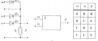
Functional
This type of diagram is used to explain the principles of operation of the system. The functional element is marked with a large rectangle. The purpose of the block is written inside: control, coordination, etc. The arrows of inputs and outputs are supplemented with explanations about power circuits and peripheral equipment.
Fundamental
In this drawing, individual elements, devices, and mutual connections are indicated by graphic symbols. When designing power lines, you can use a relatively simple single-line diagram. Fundamental - used to develop complex systems containing different types of circuits and devices.
Assembly
This document simplifies installation work. The diagram indicates not only the types of components, but also the distances between them. Information about chain lengths can be used to purchase cable products. Special marks indicate fastening features, ratings, and sequence of work operations.
Voltage and resistance maps
A voltage map (diagram) is a drawing in which, next to the individual parts and their terminals, the voltage values characteristic of the normal operation of the device are indicated. Voltages are placed in the gaps of the arrows, showing in which places measurements need to be made. The resistance map indicates the resistance values characteristic of a working device and circuits.
Letter designations on electrical circuits
To provide more complete information about the device, it is signed with an abbreviated letter designation. The number of letters is 2 or 3. Sometimes the letter designation turns into an alphanumeric one if you put the device serial number next to it.
Along with international ones, there are also Russian standards. They are listed in GOST 7624-55, but this document is declared invalid.
The article does not provide information about all symbols. Complete materials on graphic symbols can be found in GOST 2.709-89, 2.721-74, 2.755-87.
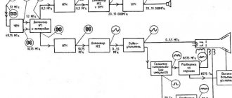
Current-carrying, switching, lighting equipment
Table. Conventional graphic images of electrical equipment and wiring on plans. Excerpt from GOST 211.614–88.
| Name | Image | Size, mm | |
| 1 | 2 | 3 | |
| Wiring and conductor lines | |||
| Wiring line (general image) It is allowed: to indicate above the line image the wiring data (type of current, voltage, material, installation method, wiring mark, etc.); indicate the number of conductors in the line with serifs | Thickness 1.0 | ||
| Examples | Same | ||
| 110V DC circuit | |||
| line consisting of three conductors | |||
| Control line | |||
| Emergency evacuation and security lighting network line | |||
| Line voltage 35 V and below | |||
| Grounding and grounding line | |||
| Grounding switches | |||
| Metal structures used as grounding and grounding lines | |||
| Laying wires and cables | |||
| Open laying of one conductor | Thickness 1.0 | ||
| Open routing of multiple conductors | |||
| Open laying of one conductor under the ceiling | |||
| Open laying of several conductors under the ceiling | |||
| Laying on the cable and its end fastening | |||
| Wiring in the box | |||
| Wiring in the box | |||
| Vertical wiring | |||
| Posting goes to a higher level or comes from a higher level | |||
| The posting goes to a lower level or comes from a lower level | |||
| The wiring crosses the mark shown on the plan from top to bottom or bottom to top and does not have horizontal sections within this plan | |||
| Wiring in pipes (general image) | |||
| Wiring in a pipe through the wall | |||
| Wiring in the pipe through the ceiling | |||
| Laying busbars and busbars (general image) | Thickness 2.0 | ||
| Busbar laid in insulators | Diameter 5.0 | ||
| Bus or busbar on racks | Diameter 4.0 | ||
| Bus or busbar on suspensions | |||
| Busbar or busbar on brackets | |||
| Trolley line | |||
| Trolley line sectioning | |||
| Trolley line sectioning | Radius 2.5 | ||
| Boxes, panels, boxes with equipment, cabinets, panels, consoles | |||
| Branch box | Diameter 5.0 | ||
| Introductory box | |||
| Main panel for working lighting | |||
| Panel of group working lighting | |||
| Group emergency lighting panel | |||
| Equipment box | |||
| Cabinet, panel, remote control, one-way service panel, local control station | |||
| Cabinet, two-way service panel | |||
| Cabinet, panel, remote control, panel made of several panels for one-way service. Example: panel of four cabinets | |||
| Cabinet, panel, remote control, panel made of several panels for double-sided service. Example: panel of five cabinets | |||
| The shield is open. Example: panel of four control panels | |||
| Switches, switches and sockets | |||
| Switch (general designation) | Diameter 2.0 | ||
| Switch for surface installation with degree of protection from IP20 to IP23: | |||
| single-pole | Same | ||
| single pole double | Same | ||
| single-pole triple | Same | ||
| bipolar | Same | ||
| three-pole | Same | ||
| Switch for concealed installation with degree of protection from IP20 to IP23: | |||
| single-pole | Diameter 2.0 | ||
| single pole double | Same | ||
| single-pole triple | Same | ||
| bipolar | Same | ||
| Switch for surface installation with degree of protection from IP44 to IP55: | |||
| single-pole | Diameter 2.0 | ||
| bipolar | Same | ||
| three-pole | Same | ||
| Two-way switch without zero position with degree of protection from IP20 to IP23: | |||
| single-pole | Diameter 2.0 | ||
| bipolar | Same | ||
| three-pole | Same | ||
| Two-way switch without zero position with degree of protection from IP44 to IP55: | |||
| single-pole | Same | ||
| bipolar | Same | ||
| three-pole | Same | ||
| Plug socket (general picture) | |||
| Surface-mounted socket with degree of protection from IP20 to IP23: | |||
| bipolar | Same | ||
| bipolar double | Same | ||
| two-pole with protective contact | Same | ||
| three-pole with protective contact | Same | ||
| Recessed socket outlet with degree of protection from IP20 to IP23: | |||
| bipolar | |||
| bipolar double | Same | ||
| two-pole with protective contact | Same | ||
| three-pole with protective contact | Same | ||
| Plug socket with degree of protection from IP44 to IP55: | |||
| bipolar | Same | ||
| two-pole with protective contact | Same | ||
| three-pole with protective contact | Same | ||
| Units with switches and two-pole sockets for surface installation with degrees of protection from IP20 to IP23: | |||
| one switch and plug socket | Same | ||
| two switches and a plug socket | Same | ||
| three switches and a plug socket | Same | ||
| Units with switches and two-pole plug socket for flush installation with degree of protection from IP20 to IP23: | |||
| one switch and plug socket | Same | ||
| two switches and a plug socket | Same | ||
| three switches and a plug socket | Same | ||
| Lamps and spotlights with separate images on the plan of equipment and electrical networks | |||
| Lamp with incandescent lamp (general designation) | |||
| Luminaire with fluorescent lamp (general designation) | |||
| Luminaire with high pressure discharge lamp. | |||
| Spotlight, e.g. with incandescent lamp (general designation) | |||
| Incandescent lamp for emergency lighting | |||
| Luminaire with fluorescent lamp for emergency lighting | |||
| Fixture with incandescent lamp for special lighting (light indicator), e.g. for emergency exit | |||
| Lamps and spotlights with separate images on the plan of equipment and electrical networks | |||
| Lamp with incandescent lamp (general designation) | Diameter 5.0 | ||
| Lamp with incandescent lamp on a cable | Diameter 5.0 | ||
| Lamp with an incandescent lamp on a bracket, on the wall of a building, structure for outdoor lighting | |||
| Lamp with fluorescent lamps. Note: it is allowed to depict a lamp with fluorescent lamps to the scale of the drawing | |||
| Lamp with fluorescent lamps installed in a line | |||
| Luminaire with fluorescent lamp on a bracket for outdoor lighting | |||
| Luminaire with high pressure discharge lamp on bracket for outdoor lighting | |||
| Luminaire with high pressure discharge lamp on pole for outdoor lighting | Same | ||
| Chandelier | Same | ||
| Lamp – slotted light guide | |||
| Spotlight | |||
| A group of spotlights with the optical axis directed in one direction | |||
| A group of spotlights with the optical axis directed in all directions | Diameter 6.0 | ||
| Control equipment | |||
| Starting device for electric motors (general image) | |||
| Magnetic switch | |||
Table. Conventional graphic images of electrical equipment and wiring on plans. Excerpt from GOST 21.614–88. Conditional images
| Name | Image |
| Electrical devices and electrical receivers | |
| Electrical device (general image) | |
| Electrical device, for example with an electric motor | |
| Multi-motor electric drive device | |
| Device with generator | |
| Engine - generator | |
| Complex transformer device with one transformer. Note: it is allowed to depict a low-power transformer without a rectangular contour | |
| The same with several transformers | |
| Complex condenser installation | |
| Complex converting installation | |
| Accumulator battery | |
| Electric heating device (general designation) | |
| Electrical equipment of open switchgears | |
| Power transformer: | |
| oil with expansion tank | |
| oil without expansion tank | |
| Oil switch, voltage: | |
| 6…10 kV | |
| 35 kV | |
| 110… 220 kV | |
| Disconnector, separator voltage 35, 110, 220 kV | |
| Short circuit, grounding switch voltage 35, 110, 220 kV | |
| Automatic high speed switch | |
| Concrete reactor | |
Electrical panels, cabinets, boxes
On the power supply diagrams of a house or apartment there will definitely be a designation of an electrical panel or cabinet. In apartments, the terminal device is mainly installed there, since the wiring does not go further. Houses can be designed to install an electrical branch cabinet - if there is a route from it to illuminate other buildings located at some distance from the house - a bathhouse, a summer kitchen, a guest house. These other symbols are in the next picture.
Designation of electrical elements on diagrams: cabinets, panels, consoles
If we talk about images of the “filling” of electrical panels, it is also standardized. There are symbols for RCDs, circuit breakers, buttons, current and voltage transformers and some other elements. They are shown in the following table (the table has two pages, scroll by clicking on the word “Next”)
NumberNameImage on the diagram
| 1 | Circuit breaker (automatic) |
| 2 | Switch (load switch) |
| 3 | Thermal relay (overheat protection) |
| 4 | RCD (residual current device) |
| 5 | Differential automatic (difavtomat) |
| 6 | Fuse |
| 7 | Switch (switch) with fuse |
| 8 | Circuit breaker with built-in thermal relay (for motor protection) |
| 9 | Current transformer |
| 10 | Voltage transformer |
| 11 | Electricity meter |
| 12 | A frequency converter |
| 13 | Button with automatic opening of contacts after pressing |
| 14 | Button with contact opening when pressed again |
| 15 | A button with a special switch to turn off (stop, for example) |
Graphic symbols in electrical engineering
Graphic symbols are divided into basic images, bus and wire symbols, line diagram symbols, socket symbols and other elements.
The main basic images are mandatory, they are easy to understand even for a novice master, not a single electrical appliance can do without them. The device contains resistors, capacitors, coils, diodes, contacts - all of them are assigned designations. Individual elements, such as coils, are small and used almost everywhere, which is confusing for beginners. It will not be superfluous to know schematic images of these elements.
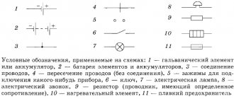
Some examples of basic images:
- diodes are indicated by a triangle intersected by a line;
- a circle with a diameter of 12 mm indicates transistors;
- a rectangle is used to designate a resistor (size 4x10mm);
- coils are depicted by arc lines in the amount of 2 to 4, it all depends on the purpose;
- The contact icon is an open line with a 6 mm segment at one end.
The basic images include the functions of moving and fixed contacts, indicated in the diagrams.
Images of wires, cables and buses
These images consist of lines: straight, dotted, crossed. They connect all the elements in the correct sequence. Let's take a closer look at their types and meaning:
For example, a straight line with a dot at the end indicates where a wire ends, and a line of multiple wires will have tick marks. If necessary, it is allowed to indicate above the lines the types of current, the order of wiring, the voltage value and other marks.
Symbol for wiring on electrical circuits
Designation of wiring in pipes and corrugated hoses
Designation for laying busbars and busbars
Wires that differ in purpose and installation method are shown schematically. All designations will help you choose the material suitable for installation work and allow you to judge the power of the electrical network.
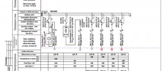
How are single line diagrams depicted?
Single-line diagrams will be needed to assemble electrical panels. They are based on a residual current device (abbreviated RCD), contactors, automation, neutral and ground buses, and other equipment. When working with such a scheme, you need to be especially careful, since some of the symbols are of a similar nature. An example is relay coils, for which only a rectangle is used for graphics. The contactor and switch are designated in the same way; the main thing here is to notice one small element on the stationary contact.
When drawing up a single line diagram, it is important to understand that some symbols are indicated by several icons: for example, the presence of two check marks in a row indicates the number of wires.
Designations of lamps and fixtures
These symbols are especially necessary if the house has complex lighting installations. Unlike other notations, they are quite simple and easy to remember.
For example, a regular circle denotes a lamp with a halogen or incandescent lamp; a narrow and long rectangle indicates a fluorescent lamp. There are special symbols even for lamp sockets.
Designation of lamps on electrical circuits
Understanding these signs is useful for anyone who plans to draw up an energy supply plan for their home.
Graphic images in electrical circuits
An electrical network drawing is a set of graphic elements that together form an inextricable system. In practice, this is a set of devices connected by wires.
Read also: How to make molds for casting
Most of the symbols are graphic. Letters and numbers are used to symbolically designate individual elements, their denominations and distances between objects.
Main base images
Electrical circuits lead to devices and installations that are equipped with contacts that can break or connect these circuits.
The simplest example is an ordinary switch. All contacts are divided into make, break and switch contacts - these are the ones that are displayed in the diagrams.
The listed graphic images are mandatory when drawing up circuit diagrams and are usually understandable even to a novice electrician.
Single Line Diagram Symbolism
Drawings are also used to assemble electrical panels. They are usually a single line diagram indicating RCDs, circuit breakers, contactors and other protective equipment.
Some graphic symbols are similar to each other, so special attention is required when drawing up a diagram. For example, a contactor and a switch are designated the same, the difference is in a small element on the fixed contact.
Relay coils are designated by special symbols - in all images a rectangle is used as a basis.
To remember icons, associations or alphabetic clues are often used. For example, a motor drive is represented by a circle with the letter “M” inside it.
When drawing up a diagram, it should be borne in mind that quantity is also important for designating some symbols.
For example, if you need to indicate a 4-pin terminal block, then you should draw four crossed out circles in a row, and not one. Paired checkmarks when depicting sockets indicate the number of wires.
How are tires and wires depicted?
Linear graphics are used to designate buses, cables and wires - almost all symbols consist of straight lines.
Conductor connections are indicated by dots. If there is no mark at the junction of two lines, then this is a simple intersection.
Wires vary in type, purpose, load, and installation method. All this can also be shown schematically.
Additional characteristics facilitate the selection of materials and installation of the electrical network. In the future, thanks to the characteristics indicated in the diagram, one can judge the potential capabilities of the already installed electrical system.
Sockets and switches on diagrams
The designation of switches is divided into several groups - according to the degree of protection, installation method (hidden or open). There are separate switches for two directions. 2- and 3-gang switches are designated differently.
Some light source control devices do not have symbols - for example, push-button devices and dimmers.
Nowadays, to save energy in large rooms, pass-through switches are often installed, which are controlled from 2 or 3 points. You can also find corresponding icons for them.
Sockets, like switches, are divided into groups according to the degree of protection. Within groups, devices are divided by the number of poles and the presence of protection. To designate blocks, alphanumeric signatures are used, indicating the number and purpose of installations in one block.
When memorizing the designations of various electrical elements on the diagrams, each conventionally depicted device should be correlated with a real product.
For example, popular types of sockets look like this:
In reality, electrical installation devices look like this:
Switches and sockets are one of the most “in demand” elements in circuits for home use, so they should be remembered first. Read more about the designation of such devices in drawings and diagrams in this article.
Designation of light sources
Separate symbols are also provided for different types of lamps and fixtures. Conveniently, there are special icons for LED and fluorescent light bulbs.
Standard images of various types of lamps are often used to draw up installation diagrams.
If you use the same symbols, you will have to include additional clarifications, but with standard symbols you can draw a diagram much faster.
Elements for drawing up electrical circuit diagrams
The basic symbols for circuit diagrams differ little, but in addition to them there are also special symbols for designating all kinds of radio elements: thyristors, resistors, diodes, etc.
There are separate symbols for radio devices, but they are usually not required when designing a home electrical network.
Letter symbols on electrical circuits
All devices are signed in Latin letters and, if necessary, given a serial number.
Most often, single-letter symbols are used. Thus, the letter A belongs to the “Device” group, which includes lasers, amplifiers, electrical machine units and other devices. Group B consists of microphones, pickups, thermoelectric elements and microphones. In other words, these are devices where non-electrical quantities are converted into electrical ones.
For detailed decoding, it is customary to use symbols of two or more letters. The first character will be required to understand, for example, the device group of an electrical appliance, and the second letter will indicate the element included in its composition. For example, the designation BM would indicate a microphone. It seems that everything is simple, the main thing is to remember these symbols.
Let's look at some more examples of double letter codes:
- QF - automatic switch in power circuits (F - belongs to the group of protective devices);
- SF - automatic switch in control circuits;
- the letters KT denote a time relay, and KV a voltage relay;
- active energy meter PI;
- reactive energy meter PK.
Letter designation of sound alarm devices, power supply, photocell, relay, etc.
Letter designation of ammeter, ohmmeter, voltmeter, potentiometer, current transformer, antenna
Letter designation: contact connections, devices with electromagnetic drive, filters
A novice electrician needs to know a large amount of information and read diagrams accurately. The operation of electrical devices and the safety of people depend on this. Sometimes it's not just about desire, but also about training. Without basic knowledge about electricity, it will be difficult to understand even basic symbols and diagrams. It will be useful to build a few circuit diagrams yourself in order to learn how to do this perfectly.
One-letter symbolism of elements
Letter codes corresponding to individual types of elements most widely used in electrical circuits are combined into groups designated by one symbol. Letter designations correspond to GOST 2.710-81. For example, the letter “A” refers to the “Device” group, consisting of lasers, amplifiers, remote control devices and others.
The group denoted by the symbol “B” is deciphered in the same way. It consists of devices that convert non-electrical quantities into electrical ones, which does not include generators and power supplies. This group is complemented by analogue or multi-digit converters, as well as sensors for indications or measurements. The components themselves included in the group are represented by microphones, loudspeakers, sound pickups, ionizing radiation detectors, thermoelectric sensitive elements, etc.
All letter designations corresponding to the most common elements are combined into a special table for ease of use:
| The first letter character required to be reflected in the marking | Group of main types of elements and devices | Elements that make up the group (the most typical examples) |
| A | Devices | Lasers, masers, remote control devices, amplifiers. |
| B | Equipment for converting non-electrical quantities into electrical ones (without generators and power supplies), analogue and multi-charge converters, sensors for indications or measurements | Microphones, loudspeakers, sound pickups, ionizing radiation detectors, sensitive thermoelectric elements. |
| C | Capacitors | Capacitors with different capacities |
| D | Microassemblies, integrated circuits | Digital and analog integrated circuits, memory and delay devices, logic elements. |
| E | Miscellaneous elements | Various types of lighting devices and heating elements. |
| F | Designation of the fuse on the diagram, arresters, protective devices | Fuses, arresters, discrete current and voltage protection elements. |
| G | Power supplies, generators, crystal oscillators | Rechargeable batteries, power supplies on an electrochemical and electrothermal basis. |
| H | Signal and indication devices | Indicators, light and sound signaling devices |
| K | Contactors, relays, starters | Voltage and current relays, time relays, electrothermal relays, magnetic starters, contactors. |
| L | Chokes, inductors | Chokes in fluorescent lighting. |
| M | Engines | DC and AC motors. |
| P | Measuring instruments and equipment | Counters, clocks, indicating, recording and measuring instruments. |
| Q | Switches and disconnectors in power circuits | Power circuit breakers, short circuiters, disconnectors. |
| R | Resistors | Varistors, variable resistors, thermistors, potentiometers. |
| S | Switching devices in signaling, control and measuring circuits | Various types of switches and switches, as well as switches triggered by various factors. |
| T | Transformers, autotransformers | Stabilizers, voltage and current transformers. |
| U | Various types of converters and communication devices | Rectifiers, modulators, demodulators, discriminators, frequency converters, inverters. |
| V | Semiconductor and vacuum devices | Diodes, thyristors, transistors, zener diodes, vacuum tubes. |
| W | Antennas, lines and elements operating at ultrahigh frequencies. | Antennas, waveguides, dipoles. |
| X | Contact connections | Sockets, current collectors, pins, dismountable connections. |
| Y | Mechanical devices with electromagnetic drive | Cartridge brakes, electromagnetic clutches. |
| Z | End devices, limiters, filters | Quartz filters, modeling lines. |
Element base for electrical wiring diagrams
When drawing up or reading a diagram, the designations of wires, terminals, grounding, zero, etc. are also useful. This is what a novice electrician simply needs, or in order to understand what is shown in the drawing and in what sequence its elements are connected.
NumberNameDesignation of electrical elements on the diagrams
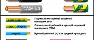
| 1 | Phase conductor |
| 2 | Neutral (zero working) N |
| 3 | Protective conductor (ground) PE |
| 4 | Combined protective and neutral conductors PEN |
| 5 | Electrical communication line, buses |
| 6 | Bus (if it needs to be allocated) |
| 7 | Busbar taps (made by soldering) |
An example of the use of the above graphic images is in the following diagram. Thanks to the letter designations, everything is clear even without graphics, but duplication of information in diagrams has never been superfluous.
An example of a power supply diagram and a graphic representation of the wires on it
Sources https//lightika.com/raznoe/uslovnye-oboznacheniya-v-razlichnyh-elektricheskih-shemah.html https//yato-tools.ru/raznoe-2/uslovnye-graficheskie-oboznacheniya-v-elektricheskix-sxemax-uslovnye- oboznacheniya-v-elektricheskix-sxemax-gost-7624-55.html https//panelektro.ru/ampery/osnovnye-oboznacheniya-v-elektricheskih-shemah.html https//www.RadioElementy.ru/articles/oboznachenie-radiodetalei- na-shemah/ https//ProFazu.ru/elektrooborudovanie/oboznacheniya/uslovnye-oboznacheniya-v-elektricheskih-shemah.html https//eti.su/articles/spravochnik/spravochnik_1632.html https//stroychik.ru/elektrika/uslovnye -oboznacheniya-na-shemah https://www.bazaznaniyst.ru/oboznachenia-v-elektricheskix-chemah/
How helpful was the article?
Click on the star to rate!
Average rating 0 / 5. Total ratings: 0
No ratings yet. Do it first.