Graphic designation of electrical machines
For schematic designation, a special ESKD system was developed, according to which any engine can be displayed on the drawing. It is represented as a circle, next to which a letter designation may be indicated. For example, DG is the main engine, DSh is the machine spindle feed electric motor, DO is the cooling pump, etc. Let's consider which UGOs the system standardizes; their full list is given in GOST 2.722-68
DC motors
DC machines have a symbol depending on the excitation option. The figure shows a DC electric motor with various UGO options.
In addition, there are many devices with additional functions. For example, a reversible electric motor with two windings or with parallel excitation and a vibration speed controller. Below are the UGOs of such devices.
Asynchronous machines
Asynchronous electric motors are depicted in the drawings as a circle, inside which there is a smaller circle representing the rotor.
The illustration shows a graphic designation of an asynchronous electric machine with a squirrel-cage rotor on a single-line diagram. For a three-phase network, the symbolic representation of a phase- and short-circuited motor is performed in a similar way, the only difference being the number of wires and the connection of the rotor circuit.
Moreover, if the electric motor is three-phase, the winding connection diagram is indicated. For example, a star connection is indicated as follows:
Each type of three-phase asynchronous machines has a different appearance in the drawing. Below are options for graphic designations of engines of various designs.
Synchronous machines
Synchronous machines according to GOST are presented in the form shown in the illustration below, and the diagram is easy to read even by a non-specialist.
A salient-pole machine with an armature winding is shown in the diagram as two circles, here wires are connected to both the outer and central ones (to the stator and rotor, respectively).
If the windings are connected by a triangle, then the synchronous electric motor will be depicted in the drawing somewhat differently.
The remaining varieties of UGO types of electric motors in the diagrams are presented with a description in the figure below.
Generators
The designation of three-phase generators, as well as synchronous motors, has the same graphic design. Below are the images that appear on the diagram.
UGO of other types of electrical machines
In addition to common devices, special ones are used, which also have their own designation in the diagram.
Special devices such as selsyn sensors and receivers have, in addition to a graphic designation, also a letter description, which is illustrated in the figure below.
The motor-converter is shown on the diagram in accordance with the UGO. Its outline on the diagram is shown in the illustration.
Here are devices that have a collector unit. It has a UGO in the form of two rectangles on the sides of a circle.
General scheme for marking electric motors
1. Series designation:
AIR, A, 4A, 5A, AD, 7AVER - general industrial electric motors with power adjustment according to GOST 51689-2000
AIS, 6A, IMM, RA, AIS - general industrial electric motors with power binding according to the European standard DIN (CENELEC)
AIM, AIML, VA, AV, VAO2, 1VAO, 3V - explosion-proof electric motors
AIU, VRP, AVR, 3AVR, VR - explosion-proof mining electric motors
A4, DAZO4, AOM, DAV, AO4 - high-voltage electric motors
2. Sign of modification:
M - modernized electric motor (for example: ADM63A2U3)
K-electric motor with a wound rotor (for example: 5 ANK280A6)
X-electric motor with aluminum frame (for example: 5AMX180M2U3)
E- single-phase electric motor 220V (for example: AIRE80S2U3)
N - protected electric motor with self-ventilation (for example: 5AN200M2U3)
F - protected electric motor with forced cooling
C- electric motor with increased slip (for example: AIRS180M4U3)
B- built-in electric motor (for example: ADMV63V2U3)
P - electric motor with increased starting torque (for example: AIRR180S4U3)
P-electric motor for driving a fan in poultry farms (“poultry house”)
3. Dimensions (height of the shaft rotation axis above the mounting surface) mm:
50, 56, 63, 71, 80, 90, 100, 112, 132, 160, 180, 200, 225, 250, 280, 315, 355, 400
4. Installation dimensions or core length:
A, B - core length option
S, M, L - variant of core length and installation dimensions along the length of the bed
X, XK, Y, YK - stator core length option for high-voltage motors
5. Number of poles:
2 (3000 rpm), 4 (1500 rpm), 6 (1000 rpm), 8 (750 rpm), 10 (600 rpm), 12 (500 rpm)
4/2, 6/4, 8/6, 12/4, 12/6, 6/4/2, 8/6/4, etc. — multi-speed electric motors
6. Sign of design modification:
B - electric motor with built-in winding temperature protection sensor
B1 - electric motor with temperature protection sensor for windings and bearing units
B2 - electric motor with winding temperature protection sensor and heater
E - electric motor with built-in electromagnetic brake (for example: AIR80A2EU3)
E2 - electric motor with built-in brake and release handle
P - electric motor with increased accuracy of installation dimensions
Ж - electric motor for driving monoblock pumps (for example: AIR80A2ZHU2)
N - low noise electric motor (for example: 5AN180S4/16NLBUHL4)
L - electric motor for driving elevators (for example: 5AN180S4/16NLBUHL4)
C - electric motor for driving oil pumping units (for example: AIR180S4SNU1)
Tr - electric motor for axial fans in transformer cooling systems
P3 - electric motor for gearmotors
7. Climatic version (GOST 15150-69)
U - for a macroclimatic region with a temperate climate
UHL - for macroclimatic regions with temperate and cold climates
HL - for a macroclimatic region with a cold climate
T - for macroclimatic regions with both dry and humid tropical climates
M - for the macroclimatic region of the region with a moderately cold maritime climate
О - for all macroclimatic regions on land, except for very cold ones (general climatic version)
B - for all macroclimatic regions on land and sea, except very cold (all-climatic version)
8. Placement categories (GOST 15150-69)
1- for outdoor use
2- for use under a canopy, in tents, body trailers
3- for use in rooms without controlled climatic conditions
4- for use in rooms with artificially controlled climatic conditions
5- for use in rooms with high humidity
Electric DC motor
The era of electric motors dates back to the 30s of the 19th century, when Faraday experimentally proved the ability to rotate a conductor through which current passes around a permanent magnet. On this principle, the first direct current electric motor was designed and tested by Thomas Davenport. The inventor installed his device on a working model of a train, thereby proving the functionality of the electric motor.
The practical application of the DPT was found by B. S. Jacobi, installing it on a boat to rotate the blades. The scientist used 320 galvanic cells as a source of current. Despite the bulkiness of the equipment, the boat could sail against the current, transporting 12 passengers on board.
Only at the end of the 19th century did industrial machines begin to be equipped with synchronous electric motors. This was facilitated by the understanding of the principle of converting mechanical energy into electricity by a direct current electric motor. That is, using an electric motor in generator mode, it was possible to obtain electricity, the production of which turned out to be significantly cheaper than the cost of producing galvanic cells. Since then, electric motors have been improved and began to gain strong positions in all spheres of our life.
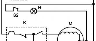
DC motor diagram with symbols
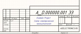
Unified system of design documentation
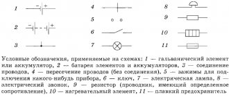
CONDITIONAL GRAPHIC DESIGNATIONS IN SCHEMES
Unified system for design documentation. Graphic identifications in schemes. Electric machinery
MKS 01.080.40 29.160.01
Date of introduction 1971-01-01
APPROVED by the Committee of Standards, Measures and Measuring Instruments under the Council of Ministers of the USSR in December 1967. The introduction period was set from 01/01/71
INSTEAD GOST 7624-62 regarding section 4
EDITION (November 2007) with Amendments No. 1, 2, 3, approved in March 1981, July 1991, March 1994 (IUS 6-81, 10-91, 5-94).
1a. This standard establishes conventional graphic symbols for rotating electrical machines on diagrams, performed manually or automatically, for products from all branches of industry and construction.
(Changed edition, Amendment No. 1, 3).
1. Three methods are established for constructing conventional graphic symbols of electrical machines:
simplified multilinear (Form I);
expanded (form II).
2. In simplified single-line symbols of electrical machines, the stator and rotor windings are depicted as circles. The terminals of the stator and rotor windings are shown in one line indicating the number of terminals on it in accordance with the requirements of GOST 2.721-74.
This standard does not provide examples of simplified single-line machine symbols.
3. In simplified multi-line symbols, the stator and rotor windings are depicted similarly to simplified single-line symbols, showing the terminals of the stator and rotor windings (Fig. 1).
4. In expanded notations, the stator windings are depicted as chains of semicircles, and the rotor windings as a circle (and vice versa).
The relative position of the windings is shown:
a) in alternating current and universal machines - taking into account (Fig. 2) or without taking into account (Fig. 3) phase shift.
b) in DC machines - taking into account (Fig. 4) or without taking into account (Fig. 5) the direction of the magnetic field created by the winding.
5. In the examples of graphic symbols of alternating current machines and universal machines, symbols are given that reflect the phase shift in the winding; in examples of DC machines - without taking into account the direction of the magnetic field.
6. The terminals of the stator and rotor windings in the designations of machines of all types can be depicted from any side.
In examples of constructing conventional graphic symbols of machines, the winding outputs are shown:
a) in AC machines: the terminals of the stator windings are up, the rotor windings are down;
b) in DC machines, the terminals of all windings are shown upward.
Design and description of DPT
Structurally, a DC electric motor is designed on the principle of interaction of magnetic fields.
The simplest DPT consists of the following main components:
The example discussed above is rather a working model of a commutator electric motor. In practice, such devices are not used. The fact is that such a motor has too little power. It operates jerkily, especially when connecting a mechanical load.
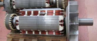
Stator (inductor)
Models of powerful modern DC motors use stators, also known as inductors, in the form of coils wound on cores. When an electrical circuit is closed, magnetic field lines are formed under the influence of the resulting electromagnetic induction.
To power the windings of the DMT inductor, various connection schemes can be used:
The connection diagrams are clearly visible in Figure 2.
Classification of asynchronous electric motors
The operation of any electrical machine is based on the principle of electromagnetic induction.
An electric motor consists of a stator (fixed part) and a rotor (armature in the case of a DC machine) (moving part). The stator contains a winding (one might say an electrical circuit), through which, having created a voltage, an electric current flows (excitation current). This current excites the machine's magnetic field, which in turn sets the moving part (rotor/armature) in motion. More precisely, the magnetic field of the stator induces a current in the rotor winding. The interaction of the magnetic field of the stator and the electric field of the rotor is the reason for the movement of the rotor; more precisely, a torque is created, which is what causes the rotation of the engine rotor. In this way, the electrical energy supplied to the excitation winding is converted into mechanical (kinetic) rotational energy. The resulting mechanical energy can be used to drive mechanisms. DESIGNATION OF ELECTRIC MOTORS
1. series (type) of the electric motor 2. electrical modifications 3. dimensions of the electric motor 4. length of the core and/or length of the frame 5. number of poles 6. design modifications 7. climatic version 8. placement category 9. degree of protection 10. power 11 .speed 12.mounting design
- Series (type) of electric motor:
- Electrical modifications:
- Electric motor dimensions
(height of the rotation axis, equal to the distance from the bottom of the legs to the center of the shaft in millimeters): - Core length
and/or bed length: - Number of motor poles:
- Structural modifications of the electric motor:
- Climatic version of the electric motor (GOST 15150-69):
- Accommodation category:
- Motor protection degree (IP, GOST 17494-87):
- Mounting design of electric motors (GOST 2479-79):
General industrial electric motors: AI - designation of a series of general industrial electric motors, P, S (AIR and AIS) - option for linking power to installation dimensions, i.e. AIR (A, 5A, 4A, AD) - electric motors manufactured according to GOST, AIS (6A, IMM, RA) - electric motors manufactured according to the European standard DIN (CENELEC). Explosion-proof electric motors: VA, AB, AIM, AIMR, 2V, 3V, etc.
M - modernized electric motor: AIRM, 5AM N - protected electric motor with self-ventilation: 5AN F - protected electric motor with forced cooling: 5AF K - electric motor with a wound rotor: 5ANK S - electric motor with increased slip: AIRS, AS, 4AS, 5AS and etc. E - single-phase electric motor 220V: AIRE, 5AEU B - built-in electric motor.
50, 56, 63, 71, 80, 90, 100, 112, 132, 160, 180, 200, 225, 250, 280, 315, 355, 400, 450 and above.
A, B, C - core length (first length, second length, third length) XK, X, YK, Y - length of the stator core of high-voltage motors S, L, M - installation dimensions along the length of the frame.
2, 4, 6, 8, 10, 12, 4/2, 6/4, 8/4, 8/6, 12/4, 12/6, 6/4/2, 8/4/2, 8/ 6/4, 12/8/6/4, etc.
E - electric motor with a built-in electromagnetic brake: AIR 100L6 E U3 E2 - electric motor with a built-in electromagnetic brake and release handle: AIR 100L6 E2 U3 B - with a built-in temperature protection sensor: AIR 180M4 BU3 Zh - electric motor with a special output shaft end for monoblock pumps: AIR 80V2 ZHU2 P - electric motor with increased precision in installation dimensions: AIR 180M4 PU3 R3 - electric motor for geared motors: AIR 100L6 R3 S - electric motor for pumping machines: AIR 180M8 SNBU1 N - low-noise electric motor: 5AF 200 MA4/24 UHL4 L — electric motor for driving elevators: 5AF 200 MA4/24 UHL4.
U - temperate climate T - tropical climate HL - cold climate OM - on ships of the sea and river fleet.
5 - indoors with high humidity 4 - indoors with controlled climatic conditions 3 - indoors 2 - outdoors under a canopy 1 - outdoors.
First digit: protection against solid objects: 0 - no protection 1 - protection against solid objects larger than 50 mm (for example, from accidental contact with hands) 2 - protection against solid objects larger than 12 mm (for example, against accidental contact with fingers) 3 - protection against solid objects larger than 2.5 mm (for example, tools, wires) 4 - protection against solid objects larger than 1 mm (for example, thin wire) 5 - protection against dust (no deposition of hazardous materials). Second digit: protection against liquids: 0 - no protection 1 - protection against vertically falling water (condensation) 2 - protection against water falling at an angle of 15° to the vertical 3 - protection against water falling at an angle of 60° to the vertical 4 - protection from water splashes from all sides 5 - protection from water jets from all sides.
The following designations for the design of electrical machines are established (1st digit): 1 - machines on feet with bearing shields: with an attached gearbox; 2 - machines on feet with bearing shields, with a flange on the bearing shield (or shields); 3 - machines without feet with bearing shields, with a flange on one bearing shield (or shields); with base flange; 4 - machines without feet with bearing shields, with a flange on the frame; 5 - machines without bearing shields; 6 - machines on feet with bearing shields and with riser bearings; 7 — machines on feet with riser bearings (without bearing shields); 8 - machines with a vertical shaft, except for machines of groups IM 1 to IM 4; 9 - machines of special design according to the installation method. Symbol for the method of installation of electrical machines of groups from IM 1 to IM 9 (2nd and 3rd digits): Note: complete tables are available in GOST. The following symbols are established for the versions of the shaft ends
of electric machines (4th digit): 0 - without shaft end; 1 - with one cylindrical shaft end; 2 - with two cylindrical shaft ends; 3 - with one conical shaft end; 4 - with two conical shaft ends; 5 - with one flanged shaft end; 6 - with two flanged shaft ends; 7 - with a flanged shaft end on side D (left) and a cylindrical shaft end on side N (right); 9 - other versions of shaft ends.
Symbols for low-power electrical machines are established by GOST 23264-78
.
The installation dimensions of the designed and modernized ones are in accordance with GOST 18709-73
.
Since the designation of engine types is in most cases not defined by standards, the designations given provide only a general structure.
Related documents:
Asynchronous electric motors for general use; Explosion-proof asynchronous electric motors; Asynchronous crane electric motors; Electric motors with increased slip.
Principle of operation
We remember from school that a buoyant force acts on a live wire located between the poles of a magnet. This happens because a magnetic field is formed around the wire along its entire length. As a result of the interaction of magnetic fields, the resulting “Amperian” force arises:
F=B×I×L, where B means the magnitude of the magnetic induction of the field, I is the current strength, L is the length of the wire.
The “Ampere” vector is always perpendicular to the magnetic flux lines between the poles. The principle of operation is shown schematically in Fig. 6.
Rice. 6. Operating principle of DPT
If, instead of a straight conductor, we take a contour frame and connect it to a current source, then it will rotate 180º and stop in a position in which the resulting force will be equal to 0. Let's try to push the frame. She returns to her original position.
Let's change the polarity of the current and try again: the frame made another half turn. It is logical to assume that it is necessary to change the direction of the current every time the corresponding turns of the windings pass the point of changing the poles of the magnets. It is for this purpose that the collector was created.
Schematically, you can imagine each armature winding as a separate contour frame. If there are several windings, then at each moment of time one of them approaches the stator magnet and is subject to the action of a buoyant force. Thus, continuous rotation of the armature is maintained.
Types of DPT
Existing DC electric motors can be classified according to two main characteristics: by the presence or absence of a brush-commutator assembly in the motor design and by the type of stator magnetic system.
Let's look at the main differences.
By the presence of a brush-collector unit
DC motors for switching windings that use brush-commutator units are called commutator motors. They cover a wide range of electric motor models. There are engines in the design of which up to 8 brush-commutator units are used.
The functions of the rotor can be performed by a permanent magnet, and the current from the electrical network is supplied directly to the stator windings. In this embodiment, there is no need for a collector, and problems associated with switching are solved electronically.
In such brushless motors, one of the disadvantages is eliminated - sparking, which leads to intense wear of the commutator plates and brushes. In addition, they are easier to maintain and retain all the useful characteristics of DPT: ease of control associated with speed control, high efficiency indicators, and others. Brushless motors are called brushless motors.
According to the type of design of the stator magnetic system
In the designs of synchronous motors, there are models with permanent magnets and DFCs with field windings. Electric motors of series that use stators with excitation flow from windings are quite common. They provide stable shaft rotation speed and high rated mechanical power.
Methods for connecting stator windings were discussed above. Let us emphasize once again that the electrical and traction characteristics of DC motors depend on the choice of connection diagram. They are different in series windings and in coils with parallel excitation.
Conventional graphic designation of electric motors in the diagram
In order to draw an electrical circuit, use conventional graphic symbols for all elements. So, in a simplified version, you can depict any element - a resistor, capacitor, electric motor, etc. They are standardized for the main types of elements; in this article we will look at the designations of electric motors in the diagram.
- Graphic designation of electrical machines
- DC motors
- Asynchronous machines
- Synchronous machines
- Generators
- UGO of other types of electrical machines
- Conclusion
Control
It is not difficult to understand that if you change the polarity of the voltage, the direction of rotation of the armature will also change. This makes it easy to control the electric motor by manipulating the polarity of the brushes.
Mechanical characteristics
Let's consider a graph of frequency versus torque on the shaft. We see a straight line with a negative slope. This straight line expresses the mechanical characteristics of a DC motor. To build it, select a certain fixed voltage supplied to power the rotor windings.
Examples of mechanical characteristics of independent excitation DC motors
Regulating characteristic
The same straight line, but running with a positive slope, is a graph of the dependence of the armature rotation speed on the supply voltage. This is the regulating characteristic of a synchronous motor.
The construction of this graph is carried out at a certain moment in the development of DPT.
An example of the regulating characteristics of an engine with anchor control
Linear characteristics make it easier to control DC motors. Since the force F is proportional to the current, by changing its value, for example with a variable resistance, it is possible to regulate the operating parameters of the electric motor.
The rotor speed can be easily adjusted by changing the voltage. In commutator engines, starting rheostats are used to achieve a smooth increase in speed, which is especially important for traction engines. This is also one of the effective methods of braking. Moreover, in braking mode, the synchronous electric motor generates electrical energy that can be returned to the power grid.