History of creation
In the 60s of the 20th century, complex relay circuits were used to control telephone exchanges and industrial equipment. They were not distinguished by increased reliability or maintainability. Engineers from one of the companies, the American General Motors, were given a goal to create new equipment. The tasks for which it was designed looked like this:
- Simplification of debugging, replacement.
- Relatively cheap.
- Flexibility, ease of upgrading.
- Reduced risk of failures.
The invention and creation of microcircuits and control units based on them made it possible to solve the questions asked.
The terminology explaining what a PLC is is included in the international and European quality standards IEC, EN.
What is a controller?
A controller is a control device used in industry, transport, other industries and in everyday life, for automatically controlling equipment according to a given algorithm. Controllers are widely used to control technological processes, maintain the physical parameters of a controlled object at a given level, and similar tasks.
One of the most promising types of controllers today is the electronic programmable logic controller (PLC), the operating algorithms of which are described in software, stored in the internal memory of the controller and executed by the microprocessor built into the PLC. The interaction of the electronic controller with the controlled object occurs through incoming and outgoing electrical signals.
Programmable logic controllers have a relatively easy-to-understand architecture and are widely used in embedded systems, automatic control, protection and control systems. Structurally, this is usually a fairly compact device, consisting of one or more interconnected electronic modules containing connectors for supplying power to the controller and connecting external input and output electrical lines, allowing the controller to interact with the outside world.
PLC structure and device
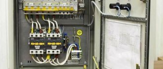
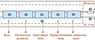
Any Siemens or similar PLC from other manufacturers is focused on performing specific actions. The microcontroller polls information input blocks to make a decision and generate a ready-made command at the output. A simplified diagram of a standard element includes:
- entrance;
- center;
- exit.
The input circuits are formed by a set of sensors (analog or digital), switching devices, and smart systems. The central block contains: a processor that processes commands, a memory module and communication means. Output circuits are responsible for transmitting signals to drive motors, ventilation, and lighting fixtures. It is also possible to connect a smart control device of the Arduino architecture or similar there. It is also necessary to fulfill the condition for connecting the PLC to the power circuits. Without them, the device will not work. An external computer through a unified interface is used for debugging and programming the controller.
PLC operating principle
In essence, a microcontroller is quite close to a relay. Only instead of mechanical contacts and coils, it contains electronic circuits. It will be easy for any engineer familiar with circuits and basic electrical engineering to understand the principle of operation.
The light sensor at the input sends a signal to the data processing unit. Under normal conditions, the processor does not respond. As soon as the sensor detects a drop in lighting, its resistance changes, the central unit activates the power circuits of the electric lamps.
A household PC is used to control the PLC and program it. Several individual microcontrollers form a cascade with complex tasks. Smart home systems and automatic activation of the pump motor for pumping water into a storage tank have long contained similar blocks.
Complex microcontroller devices provide security, protection of the perimeter (apartment), including communication with the police (owner) via a modem, raising an alarm when intruders enter, or the destruction of the door closing mechanism.
The first stage of the device operation consists of a rapid test of the equipment involved. At the same time, the operating environment and control programs are loaded. Everything is the same as on a desktop PC when Windows starts. Step-by-step processing of commands (debugging) is provided, which allows monitoring and adjustment of variables.
For ease of understanding, the operating, step mode of the PLC is divided into typical cycles. They are repeated during the operation of the device. Each cycle, “route map” contains 3 actions:
Scanning, accessing external sensors. Writing values (states) to memory cells.
Analysis of the current program. Making the required adjustments based on the data from the previous step.
Transferring the calculation result to output blocks.
The cycle ends with a quick transition to the first stage of the “lesson”.
What is a management controller?
The word controller itself literally means control. A device called a controller literally means a device designed to control something.
The simplest and most understandable example is a computer controller that controls external devices such as the computer keyboard and mouse.
To make the range of instruments and devices covered, called controllers, clear, I will give a more complex example - ControlLogix controllers. This system, based on one autonomous controller and input/output modules, allows for discrete control of constant processes, control of drives, servos in a wide variety of combinations.
Programmable controllers are used to automatically control the operation of machines, packaging processes, automation of buildings and conveyors, control of building lighting and security systems.
Another example is a smart home controller. This is the basic device for the operation of this system. Not a single smart home system can operate without control controllers. Various sensors are connected to the inputs of the smart home controller (water leaks, gas, smoke, motion sensors, etc.). Servo drives and control relays are connected to the outputs of the device, which can automatically turn off gas, water, regulate and control the house lights.
Types of PLC
All PLCs manufactured by Schneider Electric, Mitsubishi, Beckhoff, Omron, Segnetics or Unitronics are clearly divided into types. The same applies to the classification of Russian products presented by Kontar, Tekon and others. Structurally, devices are usually designated as monoblock and modular.
The first type contains a complete set of input and output circuits, a processor, and an energy source. The second involves assembling a finished PLC from individual parts. According to IEC 61131, the number and composition of modules vary in accordance with the purpose and characteristics of the device supplied to the customer.
A modular microcontroller can control, via an Ethernet connection, a low-performance counterpart that performs specifically designated functions (perimeter condition diagnostics, security of a protected area). The low-power power adapter in this case is a separate module. In general, the functionality of the second type is superior to the first. But in some situations (microcontroller for controlling a Berghof kettle), a monoblock PLC is sufficient.
The main advantage of this design is its compactness. In this case, the fully completed design of the board and controller unit is equipped with a display, an input/output device, and a button panel. A typical example is a “smart” automatic monoblock responsible for voltage stabilization.
An enlarged control unit is assembled from several PLCs mounted on a standard rail. Initially, the configuration of microcontrollers implied the replacement of existing relay, semiconductor circuits. Over time, the tasks have become more complex, but the remaining limited-performance 8 and 16-bit processors are still in demand in industry.
Cam controllers
The picture below is a cross-section of an AC cam controller:
Rolling line contact is used in the controller. Replaceable movable contact 1 can rotate relative to center O2. Center O2 is located on contact lever 2. The contact is connected via a flexible connection 4 to the output terminal.
The necessary pressing and closing of the contacts is created by spring 5, which acts on the contact lever through rod 6. When the contacts open, cam 7 acts on roller 8. In this case, spring 5 is compressed, and contacts 1 and 3 are opened. The moment of switching on and off the contacts will depend on the profile of the cam washer 9, which drives the contact elements. The arc that occurs at the moment of switching does not affect the contacts due to their rolling. Low contact wear allows you to increase the number of starts per hour to 600 at duty cycle = 60%. On both sides of the cam washer 9 there are contact elements Ⅰ and Ⅱ, which allows the axial length of the controller to be sharply reduced. As a rule, several contact elements similar to those considered are located along the axis of the device. The cam controller has a mechanism for fixing the shaft position, the same as in the drum controller. In view of facilitating the extinguishing of arcs on alternating current, only arc-resistant asbestos-cement partitions 10 are installed with cam elements, which prevent overlap between the poles of the apparatus. In such cases, the installation of arc extinguishing devices is not necessary. If the controller turns off the DC circuit, an arc extinguishing device is installed, similar to that used in contactors.
The controller design we considered has the following feature: switching on occurs due to the force of the spring, and switching off occurs due to the protrusion of the cam. Thanks to this design, the contacts can be separated in case of welding. The disadvantage of using such a system is the large torque on the shaft created by the closing springs with a significant number of contact elements.
Other designs of contacts are also possible. In one of them, the contacts open under the action of a spring and close under the action of a cam. In another case, switching on and off can be done using cams. However, such solutions are rarely used.
The figure below shows a diagram for starting an asynchronous electric motor with a wound rotor using a cam controller.
Arabic numerals indicate the positions of the apparatus shaft, and Roman numerals indicate the contacts. When starting “forward”, the contact elements located on the right come into operation. For example, consider position 3. In this position, contacts Ⅰ, Ⅱ, Ⅲ, Ⅳ are closed. With this arrangement of contacts, the stator of the machine is connected to the network, and the first positions of the stages of starting resistors in two phases are output in the rotor. In position 5, all contacts are closed - the motor rotor is completely short-circuited.
PLC Limitations
You should not assume that the presence of a programmable controller can solve all the user’s global problems. PLCs operating on the basis of Codesys and Modbus protocols (for modular solutions) have a limited scope of application. Their choice is determined by the task at hand. An attempt to create universal PLCs can hardly be considered advisable.
Such a move deprives the technological process of flexibility. Creation of the required configuration is carried out by completing a ready-made monocontroller, according to the customer’s project. In exceptional situations, the problem is solved by assembling megadevices from discrete blocks. The latter option is preferable: each element can be equipped with an individual command input panel, touch panel, and data display device.
The role of data exchange channels is played by copper cable buses and fiber optic communications. Options for standardized interfaces RS-232, RS-485 (cable), industrial Profibus or CAN are successfully used. Switching over wireless lines (Wi-Fi) is not prohibited.
Place of PLC in the control system
Modern controllers perform several functions. They can be “leaders” or “slaves”, located in the center of the diagram. Most often they are concentrated in the initial automation chain.
Before the creation of miniature integrated circuits, the operator’s hand literally did not have time to switch modes on the control circuit panel. The use of control units “Segnetix”, “Delta” and the like helped relieve the burden on humans.
It was transferred “to the shoulders” of the machines with monitoring data displayed on the screen, displayed in the form of mnemonic diagrams and changeable parameters. The PLC is tasked with polling sensors and registers and processing incoming information.
Without microcontrollers there would be no DCS, automated control system, or complex automatic control systems for technological processors. Using network traffic, PLCs analyze data, managing to check the status of input ports. The main disadvantage and peculiarity of microcontrollers is the need for firmware, creating a program for operation.
However, it should be perceived in two ways: individually created software allows you to design highly specialized products for specific tasks.
Operating principle of controllers
The controllers are equipped with a large number of inputs and outputs, where all kinds of keys, sensors and other actuators are connected. In general, all these elements are connected to the control object and produce work in real time.
The operation of the controller, in general, is very similar to the operation of ordinary microprocessors. There are two pieces of software for each universal logic controller. One of them is a system part and, in fact, is an operating system. It allows you to manage all controller nodes, perform internal diagnostics and ensure the interconnection of all components. The operating system is located in its own memory located in the central processor and is constantly ready for work.
The second part includes an application program that deals with direct control. It can be configured to perform any necessary actions, after which control returns to the system level.
Basics of PLC programming. Relay and controller
Programmability is, of course, the main advantage of PLC systems. To make the perception of the process extremely clear, the developers invented a visual display of control circuits in the form of relay contact blocks.
In professional language, this method is denoted by the abbreviation LD (logo LAD). In the future, the operation of a PLC is presented as the interaction of individual logical elements. They perform the actions of timers, relay cells, and counters. It is believed that thanks to such unification, everyone can master the principles of programming. Moreover, regardless of the profile profession.
How to make the right choice
When choosing a controller, you should pay attention to its size, level of automation, self-control and control accuracy. The last point is easy to check from reviews.
There are very expensive controllers for large and multifunctional smart home systems. But you can always find an analogue cheaper, and accordingly, with less extensive capabilities.
It is also important to pay attention to functionality. Not all controllers can perform these actions:
- lighting control in the house, in additional buildings and in the garden;
- control over temperature and humidity;
- opening and closing windows and doorways;
- control over the security system (video surveillance cameras, alarms);
- power management, automatic shutdown of sockets;
- turning on the TV and audio system;
- control over the washing machine and dishwasher;
- supervision of children and pets.
PLC programming languages
The creators of microcontrollers ensured the interaction of the devices being developed with several universal programming languages. They are conventionally divided into graphic and text. This allows the compilation of a finished software product from blocks created in different languages.
The deceptive simplicity of programming masks the difficulties that an overconfident engineer is bound to encounter. An inexperienced user can create the simplest commands. To implement complex ones, you will need to acquire special skills.
Remote control and monitoring
Various control interfaces are built into the controllers already at the design stage. Synchronization with automated control systems (SCADA and the like) is provided. The operator interacts with the PLC through an integrated panel, an I/O device, or remotely. To do this, an HMI, a specialized interface for interaction between man and machine, is connected to the unit via an interference-proof channel or cable network.
It is up to the customer to decide which of the available ways to implement the implementation, using the simplest keyboard module or touch panel. Recently, cloud storage and virtual servers have been actively used. Standard, Intranet (local) and Internet (external) connections are not left out either.
The implementation of the web interface is also possible wirelessly, on a Wi-Fi network. The methods described incredibly expand the operator's capabilities. They simplify the control of a working PLC complex.
Principle of operation
With the help of a smart home controller, many familiar processes are automated. To do this, you can leave the data that was installed by default, or configure the system specifically to suit your needs. Thus, it is necessary to plan the implementation of various actions within a specific time frame by establishing a schedule for the operation of devices.
Centralized and decentralized complex
There are two types of control system:
- Centralized. The smart home is controlled by only one controller with suitable functionality. A mini-computer with its own OS is built into the plastic case. It may include a GSM module (for remote access) and a touch screen with a push-button web interface. There are all the connectors necessary to connect to the network.
- Decentralized (regional). More than one controller is used. Each of them has limited functionality and controls the operation of similar devices or devices located in a specific room. Built-in electronic logic blocks do not have their own OS. The simplest action scenarios are executed.
A centralized system is usually more functional than a regional one.
Connection options
You can connect the controller to the smart home network in the following ways:
- Wireless local communication. This type of communication can be based on a radio signal, a Wi-Fi network or Bluetooth. Therefore, the range is limited. Control is possible from any part of the house and the area next to it. But problems will arise if the house has several floors or is lined with material that spoils the signal quality. In these cases, you will need to build in additional radio points or devices that will improve the signal quality.
- Remote wireless communication. Communication is possible only when the smart home controller is connected to global networks and communication expansion systems. For example, you can use GSM, GPRS and mobile Internet. Thus, data on the state of the smart home will be viewed from a phone, computer, laptop and tablet.
- Wired local communication. This method is rarely used anymore, despite its advantages. It fits any controller. Communication takes place using cable or electrical wiring. Next, a network switch is used (a device for connecting different nodes of a computer network).
Control will be carried out using a computer or buttons located on the touch/mechanical control panel. - Wired remote communication. This method is the most expensive because it requires cables laid specifically for the smart home. Communication takes place using special programs installed on the computer. This is convenient only for government agencies and industrial enterprises. For the home, wired remote communication is used very rarely.
We recommend reading: step-by-step instructions on how to make your own solar battery.
Application of controllers
A modern PLC, inexpensive and reliable, is used in PID controllers, Mercury type counters, and industrial devices of the DVP series. The compactness of the blocks allows them to be built into household appliances, mounted in panels and cabinets together with other electrical equipment.
An encoder connected to the controller is used in the automotive industry, reacting to changes in the steering angle. It is convenient to use PLCs when creating CNC complexes and automated systems for launching emergency pumping of wastewater in sewers. Video surveillance integrated into the security post will create a full overview of the surveillance area for the operator.
All required data will be saved on the storage medium (transferred to the network), and in case of danger, an alarm will be generated automatically. A chain of controllers is capable of managing the work of a metalworking workshop or a sewing workshop. In the home version, the PLC will turn on the light without human intervention and pump water from the well into the tank to the required level.
Drum controllers
The figure below shows the contact element of the controller.
Segment holder 2 is fixed on shaft 1 with a movable contact (segment) 3. The segment holder is insulated from the shaft with bakelite paper 4. A fixed contact 5 is placed on an insulated rail 6. Segment 3 runs onto the fixed contact 5 when shaft 1 rotates. In this way, the circuit is closed. Spring 7 provides the necessary contact pressure. There are a large number of contact elements located along the shaft. Segment holders of adjacent elements can be connected to each other, creating the necessary electrical circuit. With different lengths of segments, the sequence of closure of different circuits is achieved. Using an asterisk and a latch, the position of the shaft is fixed.
The drum controller has low contact wear resistance, which is why it has a limited number of starts per hour (240). The drum controller is used in systems with rare switching on/off of electrical circuit elements.
PLC Manufacturers
Companies from Russia, the USA, Germany, and Japan are represented on the market. These are Texas Instruments, Carel, Delta Electronics, Schneider Electric, Mitsubishi, Beckhoff, Omron, Segnetics, Unitronics. Domestic products are represented by the brands “Aries”, “Kontar”, “Tekon”.
The choice of a specific solution depends on the customer’s requirements and operating conditions. And in order to understand how PLC100, PLC110 differs from PLC160, PLC323, you will need qualifications, and possibly consultation with specialists.
What to look for when purchasing
There are a few things you need to know before purchasing a PLC. These are the factors:
Universality of the software environment. Unified languages for all hardware platforms.
Availability of controllers with distributed, integrated input/output.
Implementation of communication between a PLC and a desktop computer.
Specialized equipment. These are microsystems focused on working with a cloud service (alert option via mobile communications, mail).
Open architecture of individual PLCs.
This list creates a direction for both buyers and producers. Which of the listed criteria will be a priority is decided by the customer. With user-friendly software, operation will become more convenient. This is what experienced commissioning engineers say.
What to choose
PLC 110 "Aries" or Simatic s7 from Siemens, Modicon m340, Segnetics trim5 are clearly subordinated to the built-in instructions. They work according to an algorithm developed by the manufacturer. Software from different brands is not always compatible; this is taken into account when upgrading (replacing) or equipping process chains with automation tools.
To some, the terms step7, ms4, opc, pixel mean nothing. Experts will help you understand the catalog and the abundance of information. Deciphering the designation of a microcontroller and choosing a PLC program will be an impossible task for an ignorant person. Distinguishing, evaluating, and comparing the presented solutions are also quite complex to begin with without preparation.
Reviews, reviews, and operating experience of controller owners will help you choose your device. The right microcontroller doesn't have to be expensive. The price is determined by the functions performed and the brand of the device. Description and parameter settings are given in the device passport.
There is also a list of I/O ports and a short guide on how to connect the product. For certain types, a voltage converter may be required; the manufacturer must indicate its characteristics in the instruction manual. A good controller is one that copes with the assigned tasks.
