material provided by SIDOROV Alexander Vladimirovich
coupling
- a device designed to connect the ends of shafts and parts freely sitting on them to each other to transmit torque. Couplings are used to connect two shafts located on the same axis or at an angle to each other. The coupling transmits mechanical energy without changing its magnitude (provided that the shafts rotate uniformly).
Couplings are classified:
- by type of control: controlled - clutch, automatic;
- uncontrolled - constantly operating;
- rigid (blind) couplings: sleeve couplings (according to GOST 24246-96);
- articulated couplings – angular displacement up to 45° (according to GOST 5147-97);
- couplings with a torus-shaped shell (according to GOST 20884-93);
- cam-disk clutches (according to GOST 20720-93);
- overrunning clutches – transmission of rotation in only one direction;
A rigid flange coupling uses a bolted connection of flanges (Figure 1).
Figure 1 – Rigid flange coupling
A sleeve coupling uses a rigid sleeve that coaxially connects two shafts to each other (Figure 2) [].
Figure 2 – Bush coupling
Hydraulic coupling
- a device in which the shafts do not have a rigid mechanical connection, and the transfer of mechanical energy occurs under the action of the flow of working fluid (oil) from the pump wheel to the turbine wheel. The peculiarity of the hydraulic coupling is that it limits the maximum torque, smoothes out pulsations, and eliminates engine overload during startup and acceleration.
Electromagnetic and magnetic coupling
– the shafts also do not have a rigid mechanical connection and, in addition, it allows the transmission of mechanical energy through the sealed wall absolutely without leaks. One application is in centrifugal pumps for pumping hazardous liquids.
What is a coupling
What is a coupling? This is a mechanism for connecting drive shafts or pipelines.
What is a coupling for? The main task:
- mechanical - connect two shafts to transmit rotation;
- connecting - connect two sections of the pipeline to create a single sealed pipe.
Mechanical couplings also perform other auxiliary functions, such as limiting the maximum power on the shaft, preventing reverse rotation, and some others.
The efficiency of a coupling is determined by its design. The highest values of this parameter are found in rigid structures that transmit energy without loss.
Frictional and elastic varieties allow a loss of 2 to 15% of energy.
Coupling with serpentine spring.
Of the couplings with metal elastic elements, the most common is the coupling with a serpentine spring (Fig. 2).
It consists of two coupling halves with specially shaped teeth, in the depressions between which a serpentine-shaped spring is placed, divided into several parts. The teeth and spring are closed from the outside with a casing consisting of two halves connected to each other by bolts (Fig. 2, a) or threads (Fig. 2, b). The casing serves as a reservoir for lubricant and protects the coupling from dust. Elastic couplings with a serpentine spring are of two types: linear and nonlinear. Structurally, both types of couplings differ only in the outlines of the working surfaces of the lateral sides of the teeth. The working surfaces of the teeth of linear couplings are outlined by two straight lines forming an obtuse angle (Fig. 2, c), the apex of which serves as a support for the spring. The distance 2a between the points of contact of the spring with the teeth is constant and does not depend on the load of the spring. The working surfaces of the teeth of nonlinear couplings are outlined by arcs of circles, the centers of which are usually located in the plane of the outer ends of the teeth (Fig. 2, d). As the load increases, the spring, bending, comes into contact with the teeth along an ever-increasing length. In this case, the length 2a of its active part decreases and the spring stiffness increases. Linear couplings are predominantly used as they are the most advanced. In the absence of vibrations, nonlinear couplings are used, since the teeth of these couplings are simpler. The material of the coupling halves is steel 45 or cast steel 45L. The springs are made from spring steel 65G, 60S2, etc. The casing halves are cast from cast iron SCh15, SCh18. Rice. 2
Types of coupling connections
Mechanical couplings have many subtypes. All of them refer to permanent detachable connections.
Hard
For large structures, such as propeller shafts, they serve to permanently connect separately manufactured and transported sections into a single unit in the shipyard. Here, rigid connections are used, flanged or sleeved with a locking element.
A flange coupling is a flange machined or welded onto the end of a shaft. Bolts or studs are passed through the holes in the flange, with which it is attracted to the mating flange on another section of the shaft.
All coupling connections require strict alignment of the mating shafts. When it is violated, bending stresses and radial beats arise, deforming and destroying the connection.
The exception is the cam-disk mechanism. It was developed by John Oldham in the early 19th century specifically for parallel, but not coaxial, shafts.
Elastic
If vibration and dynamic loads occur on the shaft during operation, elastic couplings are used to absorb them. They have an elastic component to absorb energy. In flanged ones, these are polymer bushings placed on bolts or studs. In cams, the elastic element is made in the form of an elastic gear made of dense plastic.
Coupling
Serve for periodic connection and disconnection of the driven shaft from the drive shaft. In them, one part of the coupling is fixed on one shaft, and the second slides along the other shaft, engaging first and leaving it. According to their design, they are distinguished:
- Serrated. The engagement involves teeth or cams.
- Frictional. Engagement is achieved through friction. There are disc and conical couplings. The clamping is carried out by a spring. Such mechanisms can be connected with shafts rotating at different speeds; they are used to operate the clutch in vehicles and manual construction mechanisms with a gasoline drive.
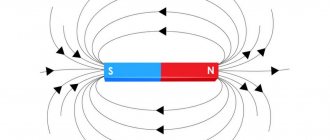
- Magnetic. The shafts are connected by the force of attraction of powerful permanent magnets; such a connection does not require physical contact, so rotation can be transmitted through a membrane or the wall of a non-magnetic vessel at the boundary of two media, for example, gas and liquid. Such drives are used for mixing liquids in the food and pharmaceutical industries.
- Hydrodynamic. The movement is transmitted by the working fluid from the driving impeller to the driven impeller. The impellers rotate in a common working chamber, but do not touch. They dampen vibrations and shocks better than others. Used in automobile transmissions.
- Electromagnetic. They act similarly, but the engagement force is provided by an electromagnet.
Types of couplings are listed in descending order of efficiency.
gebo threadless compression clamp connection
Clamping fittings of the Gebo system have appeared on the market not so long ago, but have already gained well-deserved popularity where it is necessary to connect two steel pipes. They allow you to do without labor-intensive welding or threading operations, which are not always possible due to the characteristics of the installation site. So, for example, if the joint is in a hard-to-reach place, it is impossible to cut a thread in it. Or there are flammable materials at the junction. Another option is to repair gas pipes after a leak. Welding cannot begin until the room is completely ventilated.
The Gebo fitting is a metal body with a clamping device installed at one end. A thread is cut on the body and a nut is screwed onto it. Under the nut there is a clamping ring with a conical cross-section, a clamping ring and a gasket made of elastic material. The fitting is simply put on the end of the steel pipe, the nut is screwed on and the rings compress the gasket. It is pressed tightly against the surface of the pipe, reliably sealing the connection.
Repair couplings
Used for repairing pipelines. There are two main types of such devices used:
- Butt. A piece of pipe is cut out at the location of the fault, and a repair coupling is inserted in its place. It has connections on both sides: threaded, flanged or welded. The mating parts of the connections are installed or formed at the ends of the pipeline.
- Crimping. They are a clamp placed on the damaged section of the pipe. A layer of elastic sealing material is placed under the clamp (or is part of it). The clamp tightens, pressing the caulking material against the damage and sealing it.
Crimpers serve as a means of quick, temporary repair. They should not be used on a permanent basis. They can only be installed on rigid pipes (steel, plastic) and must be replaced with a serviceable section of pipe as soon as possible.
Butt joints are used for permanent repair of rigid pipelines.
For flexible low-pressure hoses (for example, for garden irrigation or a drainage pump), they can also be used on a permanent basis. They are also used for splicing pieces of hose.
Coupling with toroidal shell.
In mechanical engineering, a number of elastic couplings are used, in which elastic rubber elements work in torsion and shear. Such couplings include, for example, couplings with elastic shells. A coupling with a torus-shaped shell (Fig. 1, c; GOST 20884-82) consists of two coupling halves, an elastic shell shaped like a car tire, and two rings that secure the shell to the coupling halves using screws. Advantages of the coupling: the ability to compensate for significant inaccuracies in the installation of the shafts being connected, ease of assembly, disassembly and replacement of the elastic element. Couplings with elastic shells have prospects for widespread use in domestic mechanical engineering.
Compared to couplings with non-metallic elastic elements, couplings with metallic elastic elements are more durable, have smaller dimensions, but are more expensive. They are used mainly for transmitting large moments.
Classification of couplings
According to the method of their functioning, couplings are divided into
- mechanical;
- electrical;
- hydraulic;
- magnetic.
According to the control possibilities, the following are distinguished:
- constant engagement;
- managed.
Controlled couplings allow shafts to be temporarily disconnected with or without stopping rotation. According to the type of drive they are divided into:
- Mechanical. Human muscular strength is used as a drive.
- Pneumatic.
- Hydraulic. They require a hydraulic system on the machine or mechanism.
- Electromagnetic. The most modern, easily integrated into digital control systems.
- Self-governing. Upon reaching a certain condition (rotation speed, torque or spontaneous reverse), we trigger a mechanism that temporarily or permanently disengages the shafts. Serve as safety devices. Due to the complexity of design, manufacturing and maintenance, they are being replaced by automated systems with sensors and electric drives.
According to the elasticity of the coupling, they are distinguished
- rigid, provide constant engagement;
- compensating, capable of working in conditions of incomplete alignment of shafts;
- elastic (compression couplings), compensate for torsional or longitudinal vibrations and shocks transmitted from the energy source;
- coupling, controlled mechanisms for commutating shafts, these include cam-disk and friction clutches.
In difficult cases, combined couplings are used that combine several classification characteristics.
The coupling is elastic with an asterisk.
The elastic coupling with an asterisk (Fig. 1, b; GOST 14084-76) consists of two coupling halves with two or three end cams of trapezoidal cross-section each. The cams fit into the corresponding depressions of the elastic element intermediate between the coupling halves - a sprocket made of rubber. This coupling is compact and reliable in operation. The material of the coupling halves is St3 steel. The dimensions of the coupling are taken according to GOST depending on the design torque Tk calculated by the formula. The rays (teeth) of the sprocket are checked by calculation for crushing. Allowable bearing stress for the sprocket [σcm]=2..10 MPa at n=1750…100 min-1.
Common installation errors
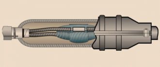
In electrical engineering, so-called heat-shrink sleeves are used, used for electrical and waterproofing of the ends and joints of electrical wires and cables. They are pieces of tubes made of special plastic, which greatly decreases in size when heated and compresses the end or joint of the wire until it is completely sealed.
Common mistakes when installing them are:
- incorrect color designation of phases or contacts
- the presence of air voids after shrinkage;
- overheating of the coupling, leading to its damage or rupture;
- incorrect selection of the initial diameter of the coupling and loss of tightness due to incomplete compression.
Careful adherence to technology and simple care when working allows you to avoid annoying mistakes