For those who deal with electrical wires every day, they know what the colors of the conductor insulation are related to. At the same time, it should be noted that wires are produced that do not have color markings. As a rule, it is more difficult to work with such electrical wires, since you have to use special tools to determine the phase and neutral conductors, as well as grounding.
General purpose of the neutral wire in transformer windings
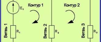
Neutral is the common, zero point connection of the conductor in three-phase transformers or generators. Currently, there are 4 main types of zero point connection:
- Isolated. This type is characterized by the absence of a neutral. The basic connection diagram for the presented network is a triangle. With single-phase ground faults on the operating phases, no changes in energy consumption are felt. A similar type is used in distribution networks of 6-35 kV.
- Resonant grounded. This option involves the use of grounding the zero point of the windings of a transformer or generator through arc suppression coils or reactors (DGC, DGR). The presence of specialized equipment compensates for the increasing current levels, allowing you to avoid more complex, interfacial faults.
- Solidly grounded. The most common type of neutral used in household networks. The winding of transformers on the low side is made with an open star connection, and the zero point is grounded through the ground loop of the transformer or transformer substation. If there is a fault on the line or a single-phase fault occurs, a potential is created relative to the ground, which activates the protection that disconnects the line.
- Effectively grounded. A type of grounded neutral, which is used in high-voltage networks of 110 kV and above. The zero point of power transformers and the fault potential are brought to ground. To increase the efficiency of protection, additional equipment is used: a single-column neutral grounding system (ZON). The position of the switching device is determined by operating instructions. For 6-35 kV distribution networks, grounding through a low-resistance resistor is used.
Colors for 220V and 380V networks
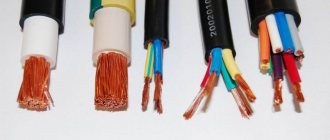
Installation of single- and three-phase electrical networks is facilitated if the wiring is made with multi-color wire. Previously, a flat two-core white wire was used for single-phase residential wiring. During installation and repair, to eliminate errors, it was necessary to ring each core individually.
The production of cable products with colored cores in different colors reduces the labor intensity of the work. To indicate phase and zero in single-phase wiring, it is customary to use the following colors:
- red, brown or black - phase wire;
- other colors (preferably blue) - neutral wire.
The phase markings in a three-phase network are slightly different:
- red (brown) - 1st phase;
- black - 2 phase;
- gray (white) - 3 phase;
- blue (blue) - working zero (neutral)
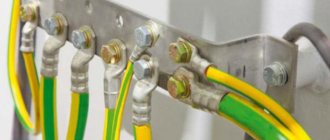
- yellow-green - grounding.
Domestic cable products comply with the standard for core coloring, so a multiphase cable contains differently colored cores, where the phase is white, red and black , the neutral is blue , and the ground is yellow-green conductors.
When servicing networks installed according to modern standards, it is possible to accurately determine the purpose of the wires in the junction boxes. If there is a bundle of multi-colored wires, the brown one will definitely be phase. The neutral wire in distribution boxes has no branches or breaks. The exception is branches to multi-pole switching devices with complete circuit breaking.
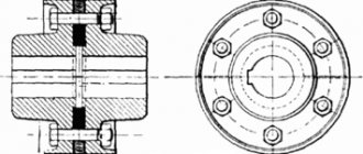
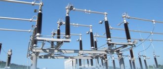
Types of connection of power transformer windings
As noted above, neutral is the connection of the neutral conductor of a three-phase power transformer or generator. To determine the type of grounding, just look at the diagram of the power equipment. For an isolated neutral, the circuit diagram is a triangle.
The remaining options are implemented through grounding the neutral conductor to ground, DGK, and a low-resistance resistor. The latter are mainly used at substations that convert high voltage electrical energy to low voltage for consumer use. The schematic diagram is a star.
Voltage 110 Volts
In some cases, the potential difference between neutral and ground is 110V, or half the network voltage. This is due to the characteristics of the electrical circuit of some household appliances. The electronic equipment of these devices, on the one hand, is sensitive to high-frequency interference, and on the other hand, is itself a source of this interference.
To protect against this phenomenon, two capacitors connected in series are installed in the device parallel to the network cable. The connection of these elements, in turn, is connected to the body of the electrical appliance and the grounding conductor of the power cable.
When the device is plugged into an outlet, a voltage of 110V appears on the body of such a device and the grounding terminal of the plug. If the electrical wiring is made according to a three-wire circuit with a grounding wire that is not connected to the grounding loop or the PE conductor suitable for the building, high voltage will appear on all grounding wires and terminals of the apartment or house.
Isolated neutral in electrical networks
Used in distribution networks 6-35 kV. As for the physical manifestations of an isolated neutral, the voltage increases to linear. The main purpose of this type is associated with the following points:
- The network does not turn off, it continues to work. Consumers on phases without a short circuit use single-phase household appliances until the line is disconnected. There is no voltage imbalance in 0.4 kV networks; in networks 6-35 it increases to linear.
- The implementation of such networks is several times cheaper to maintain, which allows saving significant funds on the distribution of electrical energy.
- High reliability of operation, especially on overhead power lines. A falling branch will not shut down the feeder and will ensure its operation.
The main disadvantages of isolated networks are:
- During a single-phase fault, the network continues to operate, the protections do not work, which sometimes leads to accidents with the population.
- The presence of ferroresonance processes and the emergence of reactive power, which deteriorates the quality of electrical energy.
Resistor and voltage 110 kV and above: how is the zero point made?
Effective grounding is a special type of neutral conductor connected to specialized equipment, which is used in electrical installations above 1 kV. For distribution networks, an option is used with grounding through low-resistance resistors, which ensure that the line is disconnected in the event of a single-phase ground fault without a time delay.
High voltage lines of 110 kV and above also use the presented type of neutral, which ensures fast response of the protection. To increase the sensitivity of the “relay” operation, each power transformer has special ZON equipment. The single-column neutral grounding switch also provides overload protection.
Protective functions of neutral and grounding conductors
To protect against electric shock if the insulation between the equipment housing and live electrical circuit elements is broken, the metal parts of the housing must be grounded. For this purpose, only the protective grounding conductor PE may be used.
Neutral N is also connected to the solidly grounded neutral of the transformer, but the connection to the ground loop using this conductor is called “grounding” and is prohibited for a number of reasons:
- the neutral wire, especially in single-phase networks, is connected through a circuit breaker, which is prohibited for protective grounding according to PUE 1.7.83;
- increased, compared to grounding, the risk of failure of this wire associated with the flow of current through it;
- when the protective grounding is broken or disconnected, there is no voltage in the socket, but the housing will be connected to the phase conductor through the network neutral and switched on electrical appliances.
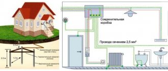
These wires are laid separately from the consumer to the transformer substation, where they are connected to the solidly grounded neutral of the transformer.
Modern PUE standards allow the installation of a combined PEN wire in the area from the transformer to the input electrical panel in an apartment building or a branch from an overhead line to a private house, where this conductor is divided into N (neutral) and PE (earth) wires.
| Important! The separation point must be additionally connected to the grounding loop of the building, after which the connection of wires is not allowed. |
Grounding through low resistance resistors
The use of low-resistance resistors is considered an ideal solution in terms of the safety of people in distribution networks, as well as in maintaining the insulation of cable lines. The implementation of protection involves connecting the zero point to specialized equipment, which has lower ohmic resistance and gives a signal to disconnect the line. The feeder turns off with a minimum time delay, which is one of the advantages. Others include:
- The first is the neutral, which, when “ground” appears, accurately determines the damaged direction and turns off the required line.
- Second: there is no need for additional calculations and compilation of regime maps with limited possibilities for looping distribution networks.
Important disadvantages of this type of grounding:
- It is not effective for high ground fault currents, as problems arise at substations where low-resistance resistors are installed.
- Low efficiency on overhead lines, as well as on long lines. In the first case, the slightest approach of tree branches will cause the feeder to turn off. This is especially true with consumers of 1 special, 1 and 2 categories.
- Unnecessary shutdowns that occur due to incorrect operation of protections (lack of automatic reclosure) involve downtime in consumption and material losses for the energy supply organization.
Solid grounding of power transformers to ground
Everything connected to the 0.4 kV distribution network is a neutral with solid grounding to the ground. The presented type has a special place and role in terms of safety. When a short circuit to ground occurs, protection is triggered, in particular, PN-2 burns out or the machine turns off. In relation to such a network, protection is also being developed for wiring in houses and apartments. A striking example is the operation of an RCD, which provides detection of leakage currents.
The main advantages of this type of neutral are:
- Ideal for distributing electrical energy, ensuring the functionality of household and specialized single-phase/three-phase equipment.
- The protection scheme does not require specialized and expensive equipment. Technical means such as fuses or circuit breakers can easily cope with solid ground faults.
Disadvantages include:
- The protections are insensitive to long-range short circuits. It is necessary to accurately calculate the ohmic resistance of the phase-zero loop and the correct choice of circuit breakers or fuses.
- Triggering does not occur if there is no ground fault. This poses a danger to humans, which is corrected through the use of insulated wires.
Educational program
Let's figure out what zero and phase are, and then move on to grounding.
A phase is a line of direct current supply. Therefore, using zero, the current returns in the opposite direction, namely to the neutral circuit. In addition, it equalizes phase voltages, performing a stabilizing role in phase wiring.
Ground (grounding wire) is not energized at all. It has one function - consumer protection. To put it roughly, the “ground” in the event of a leak will drain the residual current, preventing it from hitting a person.
I would like to think that such a simple explanation clarified the situation somewhat, and now you understand the role of each conductor from the kit: phase, neutral, ground. If you plan to work with wires yourself, then additionally, we recommend studying the color palette that manufacturers use to mark the purpose of the semiconductors inside the cable.
Resonant grounded or compensated neutrals
Resonant-grounded neutrals are used mainly in distribution networks with a voltage of 6-35 kV, where the connection diagram is carried out by cable lines. The zero point is connected through special plunger or adjustable transformers RUOM. Such a system allows you to determine the inductance in the network during a single-phase circuit, which provides compensation for the current level.
A neutral of this type reduces the risk of an accident, the transition of a single-phase fault to an interphase one. The advantages for voltage 6-35 kV are:
- The main advantage is related to the purpose of the equipment. High degree of protection for cable line insulation when properly adjusted.
The disadvantages of a network with this type of neutral are:
- Difficulty setting up. Undercompensation or overcompensation may occur, preventing proper use of the equipment. To align, it is necessary to calculate the current inductance depending on the length of the line and the power of the transformers. If the circuit is changed or power equipment is added, plunger transformers do not always cope with the assigned tasks.
- Incorrectly configured equipment and high wear on cable lines lead to a chain reaction, which involves the failure of several weak sections of the network.
- Increased technical losses that occur during operation, as well as safety problems. Current compensation at the substation is implemented relative to the ground.
- Inability to determine the line where the short circuit occurred. The process of selecting a feeder with ground is carried out through a comparison of harmonic currents, which is not always considered an effective means of obtaining reliable information.
Load voltages and currents in a system with a solidly grounded neutral
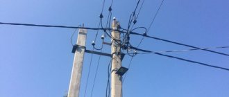
The voltage between the phases of a three-phase system is called linear. and between the phase and the working zero - phase. Rated phase voltages are 220 V, and linear voltages are 380 V. Wires or cables containing all three phases, working and protective zero, pass through the floor panels of an apartment building. In rural areas, they disperse throughout the village using a self-supporting insulated wire (SIP). If the line contains four aluminum wires on insulators, then three phases and PEN are used. The division into N and PE in this case is carried out for each house individually in the input panel.
Each consumer receives one phase, a working and a protective zero, into the apartment. Household consumers are distributed evenly across phases so that the load is the same. But in practice this does not work out: it is impossible to predict how much power each subscriber will consume. Since the load currents in different phases of the transformer are not the same, a phenomenon called “neutral displacement” occurs. Between the “ground” and the neutral conductor, the consumer experiences a potential difference. It increases if the cross-section of the conductor is insufficient or its contact with the neutral terminal of the transformer deteriorates. When the connection with the neutral is stopped, an accident occurs: in the most loaded phases, the voltage tends to zero. In unloaded phases, the voltage becomes close to 380 V, and all equipment fails.
In the event that the PEN conductor gets into such a situation, all neutralized housings of switchboards and electrical appliances become energized. Touching them is life-threatening. Separating the functions of the protective and working conductor allows you to avoid electric shock in such a situation.
Neutral conductor and arc suppression coil, reactor
The resonant-grounded neutral difference is related to the equipment used. As noted above, the zero point can be located on a plunger-type arc suppression coil or on a controlled reactor. The main differences are associated with the following points:
- DGK assumes compensation through a built-in system of plunger transformers. The setting is implemented through calculations of the real network by the relay protection service. When a ground fault occurs, current compensation occurs based on inductance. The process is not regulated or adjusted, which is an unpleasant moment in the case of “ground” appearing at several points on different lines.
- DGR is more modern equipment, which involves the use of automatic systems for determining the network inductance. Among the popular options are RUOM type reactors with SAMUR adjustment. Polling implementation is performed in real time, which ensures operability even with multiple ground faults.
It doesn’t matter whether the neutral is solidly grounded or isolated, the use of each type will find a place in the modern power industry. And knowledge of the features will allow you to understand the physical essence of the issue.