I have never thought about the operating principle of fans used in computer and office equipment. But then one of them suddenly died (Photo 1).
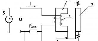
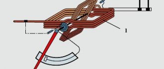
I had to perform an autopsy (Photo 2). And here a microcircuit controlled by a magnetic field was discovered - a Hall sensor. I started looking for information about the operating principle of such fans and found it in Radio magazine, 2001, No. 12, page 33. The article is called “Repairing fans of electronic devices.” My fan had a different microcircuit (Photo 2, 3). This microcircuit has two outputs that are inverse relative to each other, which change their state to the opposite when a magnet approaches and restore their state when the magnet is removed. Since I have a lot of these fans, I found a Hall sensor with three pins in one of them (Photo 4). This chip works a little differently. The state of the sensor output can be changed by changing the direction of the magnetic field, i.e. when the magnet approaches, a high-level voltage (logical one) appears abruptly at output 2 of the microcircuit; when it is removed, this voltage remains; in order to reset the output state to “0,” you need to bring the magnet to the sensor with the other pole. I conducted a small experiment, took a magnet from a TV line linearity adjustment device (Photo 5). The red line in the photo shows the zero plane between the poles of the magnet. The south pole of the magnet is marked with paint. The magnet was secured with nuts on the stud, and the stud was secured in the chuck of the mini drill. I connected the microcircuit accordingly and connected an oscilloscope to its output. When a rotating magnet approached at a speed of 9000 rpm, clear rectangular pulses were observed on the oscilloscope screen.
The advantage of such microcircuits, in my opinion, is that by changing the supply voltage of these microcircuits, their output can be coordinated with any type of hard logic. Based on them, you can create sensors for various devices. You just need to think, there is food for thought. Goodbye. K.V.Yu.
Among the elements of radio electronics, automation, as well as measuring equipment, the Hall sensor, the operating principle of which is based on the effect of the same name, occupies a special place. The meaning of the mentioned effect is that when a conductor is placed in a magnetic field, an electromotive force (EMF) appears, the direction of which will be perpendicular to the field and current. How is this used in a car?
Hall sensor - operating principle and purpose
In modern conditions, there is a constant technological development of Hall sensors. They are distinguished by reliability, accuracy and consistency of data. These devices are widely used in cars and other vehicles. They have increased resistance to aggressive external influences. Hall sensors are an integral part of many devices with the help of which a certain state of equipment is monitored.
In many cases, this device is located in the distributor and is responsible for generating a spark, that is, it is used instead of contacts. This device is often used to monitor load current. With its help, a shutdown occurs when current overloads occur. If the sensor overheats, the temperature protection is triggered. A sudden change in voltage can have serious consequences for the device. Therefore, in the latest models, an internal diode is installed that prevents the voltage from turning back on.
Until now, the Hall effect sensor has not been able to replace conventional mechanical switches. However, in any case, it has a number of significant advantages. The main ones are the absence of contacts, contamination, and mechanical stress. Therefore, you can often find a Hall sensor on a scooter, used as part of the ignition sensor.
Tachometer assembly
So, let's start in order:
Indicator
When making the tachometer, I wanted the indicator to be neatly and beautifully installed in the body of the machine control unit. As a case, I used a frame case from a failed volt/ampere meter. The TM1637 indicator board fit almost perfectly into this case. It just needed to be processed with a file - remove 1 mm from each side. I also replaced the standard pins with the XH2.54 4 pin connector. It turned out almost like a factory product.
Tachometer indicator TM1637
Hall sensor board
To accurately attach the Hall sensor to the spindle, a new printed circuit board had to be made. If anyone is interested in how I make printed circuit boards, read this article . After making the board, I transferred all the parts from KY-003, and also added the XH2.54 3 pin connector. I also cut out an insulating gasket from some kind of plastic 3 mm thick and drilled small holes in it so that the board lay flat on the gasket.
Tachometer board top view
Tachometer board bottom view
Pad
Tachometer printed circuit board on Arduino
1 file(s) 3.76 KB
Download
The board also provides space for an SMD capacitor to eliminate interference from the spindle. But so far I haven’t needed it - the shielded cable does the job.
Hall sensor - connection diagram and “physics” of the process
The classic Hall sensor device in practice is a thin semiconductor sheet material. When a direct current passes through it, a relatively low voltage is formed at the edges of the sheet. If a magnetic field passes at a right angle across the plate, then at the edges of the sheet a voltage increase occurs, which is directly proportional to the magnetic induction. A Hall effect sensor is a type of pulse sensor that produces low voltage electrical impulses. Due to its qualities, this element is widely used in contactless ignition systems .
We looked at the operating principle of the Hall sensor; its diagram is not yet clear to us. It includes a permanent magnet, a semiconductor wafer with a microcircuit, and a steel screen with slots. The steel screen passes a magnetic field through the slots, due to which voltage begins to arise in the semiconductor plate. The screen itself does not allow the magnetic field to pass through, so when the slots and the screen alternate, low voltage pulses are created.
When this sensor is structurally combined with the distributor, a single device is obtained - a distributor, which performs the functions of an ignition distributor-distributor.
DIY Hall sensor repair
Hall sensors have a very simple design and therefore rarely break down. But they cannot be called eternal. Sometimes the sensor may fail, and the “spark” disappears in the ignition system.
You can check the operation of the device yourself. The central contact of the Hall sensor is closed to a reliable ground, after which the incoming current voltage is measured (the values should be within 9-10 V). If voltage is present and other parts are operating normally, then the cause of the “spark” lies in a sensor malfunction.
In the event of a malfunction, the element requires prompt replacement. However, the price of the part in the store will hit your wallet hard. Therefore, you can try to repair the Hall sensor yourself.
The work will be carried out using a Volkswagen car as an example. The foreign car has a standard primitive Hall sensor. The repair process is very simple: you only need to replace the S 441 A logic element.
Before starting repairs, the logic element is checked for functionality. To do this, it is enough to connect an LED and a resistor (1 or 2 kOhm) in series; this structure is attached to the “plus” and “output” contacts. The electric current voltage should be from 3 to 30 V. The serviceability of the S 441 A is checked using a magnet: the LED should work.
You need to drill a small hole in the center of the Hall sensor housing with a drill. A good drill is necessary, since the plastic body of the part is reinforced from the inside with a metal frame.
Using a knife, you need to cut off each wire “flush”, and then use a file to lay grooves from the drilled hole to the remaining wires. The measuring element is installed in the housing window and its operation is checked using a magnet. If the circuit does not work, then first of all you should check the polarity of the installation of the elements.
The probe needs to be unsoldered and the pins routed along the grooves of the housing. Only the wires for the connecting connector of the old sensor should remain in the window. When carrying out work, it is important to observe the connection sequence and markings of the wires (the symbols “+”, “–” or “0” can be found on the distributor connector).
After soldering, use a tester and visual inspection to ensure that the mechanism is working properly. If there are no problems, then you can seal the hole with glue or a special compound. Experts do not recommend using plastic, as high temperatures can deform it. Some craftsmen prefer to use “cold welding” for such work.
The final stage of work is the assembly of the sensor. All actions are carried out sequentially, but in reverse order.
This repair is very simple and does not require special knowledge. It is also suitable for AUDI, Daewoo, Mittsubishi and other foreign cars.
Verification methods
You can use several diagnostic methods for the sensor located on the distributor.
Depending on the available means and capabilities, the motorist can check the current condition of the Hall controller with his own hands, evaluate its performance and make the appropriate decision on replacement.
As soon as you notice one or more of the symptoms presented, you should get checked. You can do it in several ways. I propose to consider them separately.
Wedge with wedge
The simplest and most effective method that does not require you to equip yourself with a tester or multimeter. But you will need a known-good similar Hall sensor.
The essence of diagnosis is outrageously simple. You remove the old controller and install a new one in its place. If after the manipulation the symptoms go away and engine operation returns to normal, then simply leave the new part in place. If you borrowed a DH from a friend or neighbor in the garage, remove the device, say thank you, and go to the auto parts store.
Voltmeter and multimeter
Using a voltmeter or a classic tester, you can easily check the condition of the device.
I think every motorist can use the tester. The task is to measure the voltage at the sensor output.
If the DC is in good condition, the tester will produce values in the range of 0.4-11 V.
A universal multimeter is used in exactly the same way. You just need to select the voltmeter mode on it.
Sensor simulation
Quite an interesting and effective method. But here you will have to do a little work with your own hands.
The principle of imitation is as follows. First, remove the block from the DH, which has 3 plugs. Next, start the ignition on the car, then connect outputs 3 and 6 to each other.
If a spark appears during such manipulation, then most likely the DC has failed.
Without testers
When testers are not available, testing can be done using a slightly different method.
Here you need to carry out step-by-step manipulations:
- the spark plug is connected to the wire terminal from the coil;
- the threaded part of the spark plug is connected to the ground;
- the carriage with the sensor is dismantled;
- connector is connected;
- the ignition is turned on;
- a metal object is held near the sensor;
- When a spark appears on the spark plug, the DH is operational.
Just be extremely careful when doing such manipulations with your own hands.
We repair the Hall sensor ourselves
Despite the simplicity of their design, Hall sensors do not last forever, and even on German-made cars famous for their reliability (this fully applies to products of the famous Volkswagen brand, by the way, here you can go through the entire suspension and not only) quite often there comes a time when, due to failure This element loses the “spark” in the ignition system.
In general, it is quite easy to verify that the Hall sensor is the cause of the malfunction. To do this, first of all, you should close the central contact of the sensor to the nearest reliable ground (the presence of a spark indicates normal operation of the high-voltage part), and then measure the presence of input voltage at the outer contacts of the connector, which should be about 9-10V (presence of voltage and normal operation other devices indicates a failure of the Hall sensor).
In general, the most correct solution to this problem is to install a new sensor, however, given the fairly high cost of a new part (the price of an “original” product can reach $200), it is quite understandable that many car enthusiasts want to try to repair the Hall sensor with their own hands.
As already mentioned above, the design of the Hall sensor is quite primitive and if we talk about products installed on Volkswagen cars of various modifications, then their most unreliable part is the S441A logical element (which, by and large, is a sensor, only without a magnet) and the basis of the repair process become its replacement.
In order to avoid unnecessary work, we first check the functionality of the S441A element (or its equivalent) purchased in a store or at a bazaar. For this purpose, we assemble a kind of probe from an LED and a 1-2K resistor connected in series with it and connect it to the “+” and “output” contacts (it is quite clear that the 3-30V power supply is also connected). If the sensor is working properly, then when you bring a magnet to it, the LED starts to glow.
Determining the malfunction of the Hall sensor
Before we begin repairing the Hall sensor, we need to make sure that the car does not start due to a sensor failure and not for another reason (it may simply turn out that you have not refueled your car and there is not a drop of gasoline in the gas tank). If all other reasons have been eliminated, but the car refuses to start or starts and immediately stalls, then we proceed to diagnosing the Hall sensor:
1. Using a piece of wire with stripped ends, we close the central contact of the sensor to any part of the body that has negative voltage or to the negative terminal of the battery.
The result of the check may be: a) the presence of a spark when the wire touches the negative (then everything is fine with the high-voltage part) b) the absence of a spark indicates problems with the high-voltage part of the engine
2. Using a tester, it is necessary to measure the voltage at the extreme contacts of the Hall sensor; if there is a voltage close to 9.5 Volts on them, then this indicates the serviceability of other engine control systems, and the problem lies precisely in the Hall sensor.
Since we spent our time diagnosing the sensors, and we managed to find a fault in the form of a broken Hall sensor, it would be a sin not to try a proven method to restore its functionality, as a result of which you can buy beer for 200 honestly saved dollars; the approximate cost of restoring the sensor is 10 ..15$.
Magnetic controlled microcircuits | Everything with your own hands
I have never thought about the operating principle of fans used in computer and office equipment. But then one of them suddenly died (Photo 1).
I had to perform an autopsy (Photo 2). And here a microcircuit controlled by a magnetic field was discovered - a Hall sensor. I started looking for information about the operating principle of such fans and found it in Radio magazine, 2001, No. 12, page 33. The article is called “Repairing fans of electronic devices.” My fan had a different microcircuit (Photo 2, 3). This microcircuit has two outputs that are inverse relative to each other, which change their state to the opposite when a magnet approaches and restore their state when the magnet is removed. Since I have a lot of these fans, I found a Hall sensor with three pins in one of them (Photo 4). This chip works a little differently. The state of the sensor output can be changed by changing the direction of the magnetic field, i.e. when the magnet approaches, a high-level voltage (logical one) appears abruptly at output 2 of the microcircuit; when it is removed, this voltage remains; in order to reset the output state to “0,” you need to bring the magnet to the sensor with the other pole. I conducted a small experiment, took a magnet from a TV line linearity adjustment device (Photo 5). The red line in the photo shows the zero plane between the poles of the magnet. The south pole of the magnet is marked with paint. The magnet was secured with nuts on the stud, and the stud was secured in the chuck of the mini drill. I connected the microcircuit accordingly and connected an oscilloscope to its output. When a rotating magnet approached at a speed of 9000 rpm, clear rectangular pulses were observed on the oscilloscope screen.
The advantage of such microcircuits, in my opinion, is that by changing the supply voltage of these microcircuits, their output can be coordinated with any type of hard logic. Based on them, you can create sensors for various devices. You just need to think, there is food for thought. Goodbye. K.V.Yu.
Replacing the hall sensor with initial testing with a resistor
Cars equipped with carburetor internal combustion engines have a useful element called a hall sensor. The main function of this component is to supply control pulses to the commutator, which converts them and directs them to the main winding of the bobbin (coil). Over time, the hall sensor fails, and then its skillful replacement is necessary. The article provides detailed instructions for checking and replacing, as well as a video.
Location, fixation, malfunctions
The sensor or microelectronic regulator is located in a modern distributor. Protected by anther (dust shield). It is fixed on the plate with two screws or rivets, which depends on the type of distributor model.
The microelectronic element of the car distributor is changed, as mentioned above, when it wears out for known reasons. You should know that if the sensor fails, the engine simply stalls or no longer starts.
The following symptoms may also indicate sensor malfunctions:
- at idle mode, the engine operates intermittently and jerkily;
- The car jerks when driving, especially when you switch to high speeds.
Examination
There are several ways to check the sensor. And in general, every experienced motorist knows and applies his own, favorite and for him the most effective method. We will look at the most popular diagnostic options.
- The simplest and at the same time complex/time-consuming method, which does not require special qualifications from the owner (not counting the ability to disassemble the distributor down to small parts). You just need to take a working sensor, for example, borrow from a friend, so as not to buy. And install it instead of the old one. If the internal combustion engine no longer behaves as before - it starts normally and does not jerk at high speeds, the sensor is definitely faulty.
- Take a measuring device, for example, a regular tester or resistor. Use it to measure the current at the output of the microelectronic regulator. A working car sensor should show a voltage in the range of 0.4-11 V. Other values will already indicate a malfunction.
- The third option implies the following. You need to remove the 3-pin connector from the sensor, then turn on the ignition, and connect ends 3 and 6 of the switch. If a spark appears, the sensor does not work.
How to check the Hall sensor
It is recommended to carry out the test using a simple device that every driver can do with his own hands. He will need a resistance of 1 kOhm and a simple LED. A resistance is soldered to its leg, two pieces of any length of flexible wire convenient for operation are soldered to it, and the device is ready. Checking the Hall sensor is preceded by determining the presence of power supply to it:
- the distributor cap is removed;
- the plug box from the distributor is disconnected;
- the tester is connected to terminals 1 and 3, then the ignition is turned on.
If the car's electrical wiring is functioning normally, the tester will show a voltage of 10 volts or higher. After this, we connect the designed device to the same terminals - the LED lights up if the polarity has been chosen correctly. Otherwise, you need to swap the ends of the wires. The subsequent verification scheme is as follows:
- We do not touch the wire connected to the 1st terminal, but we transfer the end from the 3rd to the free 2nd terminal;
- rotate (manually or with a starter) the camshaft.
If you notice that the LED blinks during this process, then the ignition sensor does not need to be replaced. It is also possible to check the Hall sensor with a multimeter. It is connected to the ignition output contact, setting the device to voltmeter mode. The device arrow should move in the range of 0.4-3 Volts (an indicator of the health of the sensor).
How to check the Hall sensor
Malfunctions of the Hall sensor manifest themselves in different ways; even experienced specialists are not able to accurately determine the failure. There are a number of symptoms, but they indicate problems with the sensor indirectly, because These signs happen for different reasons:
- the engine does not start;
- at idle speed fluctuates;
- while driving, when the speed increases, the car jerks;
- The engine stalls for no reason.
If such symptoms occur, it is necessary to also check the Hall sensor. In addition to the method indicated in the article, there are several more. For example, the simplest thing is to ask someone for a working sensor and simply replace it on your car; if the problems go away on their own, then the sensor is faulty.
Material on the topic: what is an electrical circuit.
If you have a multimeter at hand, checking is easier than ever. To do this, you need to set the voltage measurement game mode on the device and test the indicators at the output of the sensor; if it is working properly, the voltage will vary from 0.4 to 11 V. Another common method involves checking in the absence of sparking (if there is power in the ignition system) and consists of in sensor simulation. The block is removed from the distributor and the ignition is turned on. Next, using a piece of wire, contacts 3 and 2 on the block are closed; if a spark appears on the central channel of the ignition coil, it means that the Hall sensor is faulty and requires replacement.
It will be interesting➡ How to make a motion sensor with your own hands
Another way is to check the existence of resistance on the sensor. To do this, you need to build a simple device, which consists of a 1 Kom resistor, a light diode, and flexible wiring. Solder a resistance to the leg of the light diode, and to it two wires of such length that it is convenient for operation (not short). Then remove the distributor cap, disconnect the distributor and the plug box. Then we check whether the electrical circuit is working properly. Therefore, we connect the electronics multimeter to the first and third terminals, then turn on the car’s ignition.
Under good conditions, the measurement on the device’s screen should be within 10-12 V. Then also connect the made mechanism to the same terminals. If you did everything correctly, the light diode will light up. Otherwise, you need to change the wiring places. Next you need to do this: do not touch the wire that is connected to the first terminal, do not touch the tip from the third terminal, transfer it to the free second terminal, turn the camshaft (by hand or with a starter). If the diode blinks when turning the shaft, this indicates that the sensor should not be changed.
Replacing the Hall sensor.