For the convenience and safety of people, motion sensors have been invented that react to the appearance or presence of a person in their area of action. When a person appears in the sensor’s coverage area, the automation is triggered and any electrical equipment connected to it is activated, for example, lighting, a sound warning system, and an alarm system are turned on.
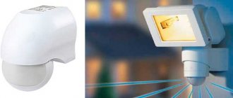
The photo shows a motion sensor, using an installation example of which I will demonstrate how to correctly connect it to electrical wiring to automatically turn on the lamp when entering a room.
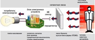
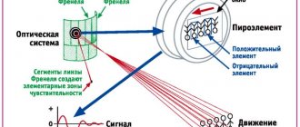
Appearance The motion sensor is a rectangular or round plastic box with a window covered with a matte plastic film, which is a Fresnel lens. Through this window, using infrared waves, the appearance of a person in the control zone is monitored. The material from which the Fresnel lens is made is delicate, and when installing and operating the motion sensor, care must be taken so as not to accidentally damage the lens.
Before installing a motion sensor, you need to choose the one suitable for solving the task based on the size of the room and the conditions under which people and animals stay in it.
Choosing a motion sensor model for your home
Based on the method of detecting the presence of a person in the control zone, motion sensors are either active or passive.
Active ones work like a radar or echo sounder. They emit a signal and analyze its reflection. If the distance that the signal travels from the sensor to the obstacle and back has changed, then it is triggered. Passive sensors simply detect heat emitted by a person. There are also combined ones, which combine active and passive control methods.
Active sensors operate in ultrasonic or high radio frequencies. The ultrasonic range lies within 20,000 Hz; humans cannot hear such a sound, but dogs, cats and other animals hear it and begin to behave restlessly. If there are living creatures in the house, then it is not permissible to use motion sensors operating in the ultrasonic range.
Active motion sensors operating at high radio frequencies do not “notice” obstacles in the form of walls or furniture, and only detect the movement of objects. If installed incorrectly, they can even react to the swaying of trees outside the window or the movement of people in a neighboring apartment, causing false alarms. Moreover, they are the most expensive.
To control the switching on of lighting in an apartment, passive infrared motion sensors that respond to heat emitted by the human body are best suited. Therefore this type is the most common.
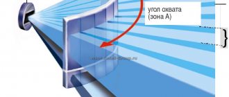
You should also pay attention to the horizontal and vertical detection angles of the motion sensor and the range. Typically, the detection area for ceiling-mounted motion sensors is 360° in the shape of a circle. Motion sensors designed for installation on walls usually have a horizontal detection angle of 180° and a vertical detection angle of about 20°.
In the drawing, blue lines indicate the outline of the room, and the figure formed by red lines is the detection zone of the motion sensor. As you can see, the detection zone does not cover the entire volume of the room, therefore, when choosing an installation location, the detection zone is the determining criterion.
The detection range of motion sensors is usually limited to 12 meters, which is quite enough for home use. If the room is large, has a non-rectangular shape or is multi-story, for example, like an entrance to a house, then in this case several devices are installed to detect the presence of a person throughout the entire area.
By design, motion sensors can be movable or fixed. The movable device allows you to change the detection zone by moving the sensor relative to the base in horizontal and vertical directions.
As you can see, this motion sensor provides the ability to change the position of its head, thanks to which, after installing it on the wall, you can change the control zone within small limits.
What types of motion sensors are there?
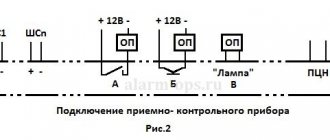
- IR detectors respond to thermal radiation emitted by surrounding objects. If they move, this is caught by special lenses. It is a passive motion sensor, as it does not emit anything into space. Resistant to sound and vibration. It is not recommended to install them in places where light rays or heat sources will be directed at the sensor. The most inexpensive and simple devices are recommended for everyday use in lighting systems. In the diagrams, the OPS is depicted as a black square with a white triangle on its right side, the top of which reaches the center of the figure;
- An ultrasonic detector is an active device, like the next type of sensor. It transmits ultrasonic waves into the environment, which then return to the device, or go to the receiver if it is located separately from the transmitter. By the nature of the changes in these waves, the device judges the movement within its visibility zones. It is not recommended to use sensors of this type in rooms where there are animals, as they hear ultrasound and this causes them anxiety. On security alarm diagrams it looks like a black square, across the entire area of which there is a white triangle, pointing to the left. There is a line from its top to its base;
- Microwave devices emit radio waves. They are more accurate and sensitive than their ultrasonic counterparts. Signals from such a sensor can pass through obstacles, and the level of radiation from them is so low that it will not cause any harm to living beings. Resistant to vibration and heat. The schematic representation of this device is similar to the ultrasonic one, with the only difference being that it is completely white;
- combined detectors require the presence of several types of sensors within one system, which makes the device the most accurate and reduces the number of false alarms to a minimum. The symbol for this sensor looks like a white square with a black triangle on its right side, from the top of which there is a line to the opposite part of the square;
- perimeter systems are located along the perimeter of the territory, covering a certain area, triggered when an intrusion into the coverage area occurs;
- peripheral ones can be installed on the walls of buildings, fences, inspecting areas in their field of view;
- indoor ones are intended for indoor use, have a less durable and resistant body and do not have such a wide temperature range at which they can remain operational;
Room motion sensor
- single-position devices are a receiver and transmitter in one housing;
- two-position - different shells for the translator and the catcher, which implies their placement in different places so that the required area is located exactly between them;
- multi-position systems are equipped with several devices, which makes it possible to monitor a fairly large area using one set of security devices;
- overhead sensors are the simplest, mounted on any flat surface;
- built-in ones are more expensive models; they allow you to disguise them if there is a need to hide them from prying eyes, or you need to maintain the design integrity of the room. They are mounted on the same plane as the work surface, which makes it possible to disguise them if the owner so requires;
- Wired detectors operate from the network and transmit a signal through wires. This results in a more stable transmission signal, which may not be available in some cases when using their wireless counterparts. In the event of a power failure, the device can be protected from shutdown by being connected to a backup generator. This is mainly practiced in large organizations, where it is undesirable to remain without power for a long time (for example, food warehouses with refrigerators), as well as in private homes;
- wireless and stand-alone devices are installed if it is not possible to run a cable to the installation site. In this case, power is supplied from a battery located inside the device. And data transmission is carried out over a wireless network - Wi-Fi or GSM. This communication method is highly dependent on electromagnetic interference, the number of obstacles between the receiver and transmitter, and can also respond to changing weather conditions. But, in general, this method is the fastest and most accurate.
Choosing a location for installing a light motion sensor
Before installing a motion sensor, in order to ensure its reliable operation and eliminate false ones, you need to take a responsible approach to choosing the installation location. It is necessary not only to provide the necessary detection zone, but also to protect the motion sensor from the influence of external factors that cause false alarms or block the operation of the sensor and take into account the need to connect it to the electrical wiring.
It is not recommended to install motion sensors near electric and central heating radiators and pipes supplying hot water, in close proximity to air conditioners, near thermal and electrical appliances that emit electromagnetic interference.
Even if you take into account all the recommendations and understand the technical characteristics, it is theoretically difficult to correctly choose the best location for installation without practice. Therefore, it is advisable to conduct a little research before performing electrical installation work.
Designation of motion sensor terminals
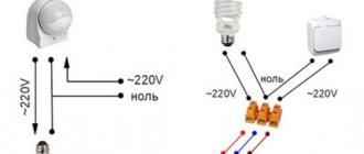
The motion sensor inside has an electronic circuit and in order for it to work, it must be connected to the supply voltage. Typically, motion sensors are designed to be connected directly to a 220 V household power supply, except for radio sensors, which are powered by a battery installed inside. The connection diagram must be on the case, usually next to the terminal block for connection. In this model of motion sensor, the markings are made directly on its body using plastic embossing.
Letter L
, with an arrow next to the terminal block, indicates the connection location of the phase wire,
N
- neutral.
The wire going to the light bulb is connected to the terminal block terminal, marked L
with a dash and an arrow pointing away from the block. You can learn about the color marking of electrical wiring wires and how to determine the phase on the website from the article “How to find the phase.”
In order for the motion sensor to start working, it is enough to apply supply voltage to the terminals of its terminal block L and N. To connect it to the electrical network, you need to take a piece of double wire, install a plug on it on one side, and connect the other end, not forgetting to remove the insulation, to the terminals L and N terminal block. The phasing of the wire connection, in this case, does not matter. Moreover, if you make a mistake and connect the wires incorrectly, then nothing bad will happen, the motion sensor simply will not work. In this case, the blinking motion sensor indicator will not light up.
In the photo, for clarity, a short piece of wire is connected. The length of the wire should ensure that the motion sensor can be connected to the nearest outlet when choosing an installation location. If you do not have a piece of wire of sufficient length, you can use an extension cord.
Typically, motion sensors have an LED that indicates what state they are in. If the sensor is connected to the power supply and is in standby mode, the LED flashes approximately once per second. When triggered, the blinking frequency of the LED increases, which allows you to know, without connecting a load, when choosing an installation location, whether the sensor has triggered or not. It should be taken into account that some types of motion sensors, after connecting to the power supply, become ready for operation after some time, 15-30 seconds.
Connection diagrams
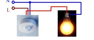
To solve various problems, motion sensors are connected using various schemes. The simplest option is to directly turn on the lighting fixture, as shown in the figure below.
Rice. 6. Motion sensor connection diagram
If you allow the possibility of switching lighting equipment bypassing the motion sensor for personal needs, then it is better to use a circuit with a bypass function:
Rice. 7. Circuit with bypass switch
As you can see, here the key switch allows you to turn on the lighting even without a signal from the sensor. For those cases when the motion sensor should be triggered only in the dark, a circuit with a photo relay is used:
Rice. 8. Circuit with photo relay
If you want the lighting equipment to be turned on by movement in several zones, then use a diagram for connecting one lamp to two or more sensors:
Rice. 9. Scheme with two motion sensors
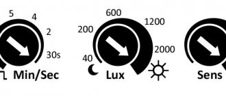
Purpose of the parameter adjustment knobs
There are knobs on the body of the motion sensor for adjusting its parameters. Depending on the model and its purpose, there are from two to four handles. Next to the knobs there is usually a letter designation of the type of adjustment, a picture of the purpose of the adjustment and the direction of rotation of the knob to change the setting. Therefore, before installing a motion sensor, you need to understand what parameter and how each of the handles affects and in what position they should be installed for optimal operation in specific conditions.
Before you start looking for a place to install the motion sensor, it is advisable to adjust its parameters on the table and mark it with a marker to make it easier in real conditions. In low light, the factory markings are difficult to see.
| Name and designation of the motion sensor parameter | |||
| Designation | Parameter name | Function | Note |
| LUX | Illumination | Adjusts the level of light at which the motion sensor is triggered | from 5 to 10000 Lux |
| TIME | Time | Duration of timer activation | from 5 to 420 seconds |
| SENS | Sensitivity | Adjusts range | up to 12m |
| MIC | Microphone | Adjusts the noise level at which the motion sensor is triggered | 30-90 db |
LUX dimmer
allows you to set a light threshold above which the motion sensor will not respond to movement.
Why turn on the lights during daylight hours if you can already see clearly. Initially you need to set it to maximum
.
TIME Timer Time Controller
motion sensor.
This is the time during which the light will remain on after the motion sensor is triggered. Initially set to minimum on time
. It should be noted that if, after the motion sensor is triggered, a person continues to move in the detection zone, the timer is restarted, and the countdown until the motion sensor turns off will begin from the moment the person stops moving. For example, if you set the timer to 10 seconds, and a person moved or waved his hands in the detection zone for 10 minutes, then the light will be on all this time.
SENS sensitivity control
Rarely installed on motion sensors, as it is of practical necessity. It happens, it is needed if you want to not control part of the room, and this can always be done by adjusting the position of the motion sensor during installation. Initially you need to set it to maximum.
MIC sensitivity control
It is present very rarely, since it is not in demand in everyday life and has low noise immunity. The noise of a passing truck or a child's scream in the entrance of a house can trigger a motion sensor. But to perform the security function, if properly adjusted, it can serve as an excellent means of protection, since the detection zone will be practically unlimited. Initially you need to set it to minimum.
Now that the preparatory work has been completed and all the controls are set to the required positions, you can begin to determine the installation location of the motion sensor. To do this, you can temporarily mount the sensor on a stepladder or board, and by placing the motion sensor in the intended installation locations, try to find the best one. As I wrote above, a rapidly blinking LED will indicate that it has been triggered.
It is convenient to connect the motion sensor for lighting to the electrical wiring in two places, in the junction box or directly at the point where the chandelier is connected to the wires coming out of the ceiling or wall. Therefore, before searching for a location to install the motion sensor, you need to determine where it is easier to connect it. It is difficult even for a professional electrician to deal with the wires in the distribution box, especially in houses built a long time ago, and the boxes are often covered with wallpaper or located under plaster. The easiest way to figure out the connection is to a chandelier or wall lamp.
After determining the installation location of the motion sensor, you can begin mounting it on the wall and installing electrical wiring.
Attention! Before connecting the motion sensor to the electrical wiring, to prevent electric shock, it is necessary to de-energize it. To do this, turn off the corresponding circuit breaker in the distribution panel and check the reliability of the shutdown using the phase indicator.
Setting and adjustment for lighting
In addition to proper connection of the sensitive element, carried out according to the diagram attached to it, its preparation for operation is mandatory, which boils down to setting a number of operating parameters. Setting up motion sensors for lighting
Motion Sensor Settings Panel
assumes the correct setting of the following values:
- illumination (labeling “LUX”);
- turn-on delay (indicated as “TIME”);
- setting the sensitivity in the connection diagram of the infrared motion sensor (under the designation “SENS”).
Let's look at each of these parameters in more detail.
Time adjustment "TIME"
Adjustments of motion sensors according to the time parameter are carried out by setting the duration of the period of time that the illuminator will burn after movement is detected in the controlled area. Typically, this parameter for standard lamps varies in the range from 1 to 600 seconds.
The speed of a person’s movement has a significant influence on the setting of this indicator. It generally depends on it whether the sensitive element will work or not.
In the case when a person moves very quickly in a controlled area, it is advisable to shorten the pause before turning off the lighting (why should the light burn in vain?). When setting up such a device in a garage or other utility room, on the contrary, it should be increased.
According to the level of illumination "LUX"
The LUX parameter is intended to correct the moment the sensor is triggered depending on the illumination in a given room. When it decreases to a certain limit, the lamp turns on automatically. The device has a mechanical regulator of the lighting threshold, which can be changed at the user's request.
In low light conditions at a given object, the LUX parameter is set to its maximum value. In rooms with high brightness it will need to be set to minimum.
Trigger sensitivity depending on the size of the moving object "SENS"
Some motion sensor models have the ability to adjust sensitivity to light (SENS). In this case, the moment of operation depends on the set indicator. If this sample is triggered quite often, reacting even to microscopic objects, its sensitivity must be reduced using the built-in regulator.
Additional information: In addition to the regulator, this can be done by simply changing the position of the sensitive element.
In addition, in such models it is possible to adjust:
- The distance at which reliable operation occurs (it should not exceed the maximum value of 10-12 meters).
- The volume of space covered by the sensitive element (this setting prevents it from triggering when birds fly by, for example).
Adjusting the motion sensor according to the volume of the captured space
In most samples working outdoors (when connecting motion sensors to a spotlight, in particular), when switching from winter to summer time, reconfiguring the device is required. This is explained by the fact that when the temperature changes, some important indicators in them get lost.
An example of installing a motion sensor in an apartment
I decided to equip the toilet with an electronically controlled bidet function. For safety and energy savings, you need to turn on the bidet control device only when necessary, that is, when a person visits the toilet. The best option is to connect in parallel with the lamp. When laying wires from the lamp to the installation site of the additional socket, I decided to install a motion sensor at the same time, so that I didn’t have to touch anything with my hands at all.
It didn’t take long to choose a location to install the motion sensor. Since the toilet room is small and windowless with a single entrance door, only one place was suitable, below the lamp.
After dismantling the lamp, the following picture opened. Two stranded ones were connected to two copper single-core wires by twisting with a clamp. The stranded wires, in turn, were connected to the lamp socket using screw terminals mounted in the socket. The wires coming out of the wall were very short and of different lengths.
In this case, it was most expedient to connect the motion sensor and an additional socket using a three-pin terminal block, which easily fit into the base of the lamp. The wires were aligned in length, the insulation was removed from them, the ends were cleaned with sandpaper, inserted into the terminal block and clamped with screws.
Before dismantling the lamp, markings were made to drill holes for dowels to mount the motion sensor on two self-tapping screws.
The plaster on the brick wall was quite loose, and the distance between the centers of the holes had to be maintained to the nearest millimeter. I used a simple jig and a certain sequence of drilling holes in the wall. To make the conductor, a piece of plywood was taken, in which two holes were drilled, 4 and 6 mm. After drilling the first hole in the wall, a dowel was inserted into it and the jig was screwed through a 4 mm hole with a self-tapping screw. A second hole in the wall was drilled through a 6 mm hole in the jig.
With this simple technique, using plywood trim, it was possible to drill holes exactly in the specified places.
All preparatory work has been done, and you can begin installing the electrical wiring and installing the motion sensor. But in order to carry out the work competently, and not just mindlessly connect the wires to each other, it is worth familiarizing yourself with the chandelier connection diagram.
Electrical diagram for connecting the sensor
As can be seen from the diagram, the neutral wire, which is designated by the letter N
, is connected directly to the chandelier light bulb, and the phase one, which is designated
L
, is connected to the second terminal of the chandelier light bulb through a switch.
In practice, you may encounter the fact that the switch opens not the phase wire, but the neutral wire. From a safety point of view, this is incorrect, but opening the neutral wire does not affect the performance of the chandelier. If there are many light bulbs in the chandelier or there is a double switch, then the chandelier connection diagram is more complex. To meaningfully connect a motion sensor, it is enough to consider how to connect it to a chandelier of one light bulb.
From a functional point of view, a motion sensor is an ordinary switch, only it turns off the light not from pressing the switch key with a person’s hand, but from movement in the detection zone. Since the motion sensor has an electronic circuit, for it to work it is necessary to apply supply voltage to this circuit.
Motion sensors are available for installation instead of a switch. But to connect it, you need one more additional wire and, of course, the detection zone with such an installation must correspond to the required one. Three wires sometimes fit to the switch to separately connect two groups of chandelier bulbs. If such use of the chandelier is not necessary and the detection zone is suitable, then you can install a motion sensor instead of the switch without laying additional wires by making connections in the junction box.
Wiring diagram
The simplest case is when the motion sensor is connected to the terminal block of the chandelier. Since my lamp did not have such a block, I had to install it. I made the connection according to the wiring diagram below.
As can be seen in the diagram, the phase wire is connected to the upper contact of the terminal block and from it goes directly to the terminal block terminal, designated by the letter L. The neutral wire is connected to the middle terminal of the terminal block and then goes to the terminal block terminal, designated by the letter N. It also goes to it two wires are connected, going to the light bulb and an additional socket.
Phase wire L is connected to the normally open contacts of the relay, in the same way as to the contacts of an ordinary key switch. Next, from the relay contact, the wire goes to the lower contact of the terminal block and is then connected to the lower contact of the chandelier terminal block. The second terminal of the light bulb and socket are also connected to the same contact. When the motion sensor is triggered, the relay closes the contacts and voltage is supplied to the light bulb and socket.
As a light source, you can connect not only incandescent lamps to the motion sensor, but also energy-saving LED lamps and monochrome and RGB LED strips connected through adapters. You can also connect a radio or any other device.
Before connecting the wires, prepare sections of them long enough for free connection with the terminal blocks. The insulation is removed from the ends of the wires and, according to the diagram, the wires are twisted together. After twisting, tinning with solder is performed using an electric soldering iron. If you do not plan to pass large currents, then it is not necessary to tin the wires.
When the ends of the wires are prepared, they are connected to the terminal block of the chandelier.
All that remains is to screw the base of the chandelier to the wall and screw the shade into it. As you can see, all the wires and the terminal block are hidden under the base of the chandelier and do not protrude anywhere.
I laid the wires to the additional outlet in a cable channel, since I didn’t want to scratch the wall and spread dirt. During the next toilet renovation, I will hide the wiring in the wall.
Now you need to make adjustments, set the timer time, the sensitivity of the motion sensor and the work can be considered complete.
Although the light has now begun to turn on and off automatically, out of habit, when approaching the door, the hand reaches for the switch, and when leaving, everyone constantly turns off the light without even noticing. I had to short-circuit the terminals of the switch on the wall so that it would no longer affect the turning on of the light, since if the light is turned off by the switch and turned on again, the motion sensor is triggered only after the time set by the timer has expired.
LEGEND
1.1. Graphic symbols
1.1.1. Graphic designations of devices, automation equipment and communication lines must correspond to those given in table. 1.
Table 1
| Name | Designation |
| 1. Device installed outside the switchboard (on site): | |
| a) main designation | |
| b) acceptable designation | |
| 2. Device installed on the panel, remote control: | |
| a) main designation | |
| b) acceptable designation | |
| 3. Actuator. General designation | |
| 4. An actuator that, when the power supply or control signal is interrupted: | |
| a) opens the regulatory body | |
| b) closes the regulatory body | |
| c) leaves the regulatory body in the same position | |
| 5. Actuator with additional manual drive Note: The designation can be used with any of the additional signs characterizing the position of the regulatory body when the supply of energy or control signal is interrupted | |
| 6. Communication line. General designation | |
| 7. Crossing communication lines without connecting to each other | |
| 8. Crossing communication lines with interconnection | |
1.1.2. The selection device for all permanently connected devices is depicted as a solid thin line connecting the process pipeline or apparatus with the device (Fig. 1). If it is necessary to indicate the specific location of the sampling device (inside the contour of the technological apparatus), it is indicated by a circle with a diameter of 2 mm (Fig. 2).
| Crap. 1 | Crap. 2 |
1.2. Letter designations
1.2.1. The main letter designations of measured quantities and functional characteristics of devices must correspond to those given in table. 2.
table 2
| Measured quantity | Functional characteristic of the device | ||||
| Designation | Basic designation of the measured quantity | Additional designation specifying the measured value | Information display | Output signal generation | Additional meaning |
| A | + | — | Signaling | — | — |
| IN | + | — | — | — | — |
| WITH | + | Automatic regulation, control | |||
| D | Density | Difference, difference | — | — | — |
| E | Electrical quantity (see clause 2.13) | — | + | — | — |
| F | Consumption | Ratio, fraction, fraction | — | — | — |
| G | Size, position, movement | + | |||
| H | Manual impact | Upper limit of measured value | |||
| I | + | — | Indication | — | — |
| J | + | Automatic switching, running around | |||
| TO | Time, time program | — | — | + | — |
| L | Level | Lower limit of measured value | |||
| M | Humidity | — | — | — | — |
| N | + | — | — | — | — |
| O | + | — | — | — | — |
| P | Pressure, vacuum | — | — | — | — |
| Q | A quantity characterizing quality: composition, concentration, etc. (see clause 2.13) | Integration, summation over time | + | ||
| R | Radioactivity (see paragraph 2.13) | — | Registration | — | — |
| S | Speed, frequency | Enable, disable, switch, block | |||
| T | Temperature | — | — | + | — |
| U | Several heterogeneous measured quantities | ||||
| V | Viscosity | — | + | — | — |
| W | Weight | — | — | — | — |
| X | Deprecated fallback letter | — | — | — | — |
| Y | + | — | — | + | — |
| Z | + | — | — | + | — |
Note. Letter designations, o, are reserved, the sign “-” is not used.
1.2.2. Additional letter designations used to indicate additional functional characteristics of devices, signal converters and computing devices are given in Appendix 1.
1.3. Symbol sizes
1.3.1. The dimensions of the conventional graphic symbols of devices and automation equipment in the diagrams are given in Table. 3.
1.3.2. Conventional graphic symbols on the diagrams are made with a solid thick main line, and the horizontal dividing line inside the graphic symbol and communication line is made with a solid thin line according to GOST 2.303.
1.3.3. The font of letter designations is accepted as 2.5 mm according to GOST 2.304.
Table 3
| Name | Designation |
| Device: | |
| a) main designation | |
| b) acceptable designation | |
| Actuating mechanism | |