Design and principle of operation
To better understand the connection diagrams of a magnetic starter, you need to understand its structure and operating principle.
The base of the starter is a magnetic circuit and an inductor. The magnetic core consists of two parts - movable and stationary. They are made in the form of the letters “Ш” with their “legs” facing each other.
The lower part is fixed to the body and is stationary, the upper part is spring-loaded and can move freely. A coil is installed in the slot in the lower part of the magnetic circuit. Depending on how the coil is wound, the rating of the contactor changes. There are coils for 12 V, 24 V, 110 V, 220 V and 380 V. On the top of the magnetic circuit there are two groups of contacts - movable and fixed.
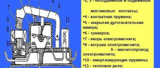
Magnetic starter device
In the absence of power, the springs press out the upper part of the magnetic circuit, the contacts are in their original state. When voltage appears (press the start button, for example), the coil generates an electromagnetic field that attracts the upper part of the core. In this case, the contacts change their position (picture on the right).
When the voltage drops, the electromagnetic field also disappears, the springs push the moving part of the magnetic circuit up, and the contacts return to their original state. This is the principle of operation of an electromagnetic starter: when voltage is applied, the contacts close, and when voltage is lost, they open. Any voltage can be applied to the contacts and connected to them - either constant or alternating
It is important that its parameters are not greater than those declared by the manufacturer
This is what it looks like disassembled
There is one more nuance: the starter contacts can be of two types: normally closed and normally open. Their operating principle is clear from the names. Normally closed contacts are switched off when triggered, while normally open contacts are closed. The second type is used to supply power; it is the most common.
Purpose and device
Magnetic starters are built into power networks to supply and disconnect power. They can work with alternating or direct voltage. The work is based on the phenomenon of electromagnetic induction; there are working (power is supplied through them) and auxiliary (signal) contacts. For ease of use, Stop, Start, Forward, Back buttons are added to the magnetic starter switching circuits.
This is what a magnetic starter looks like
Magnetic starters can be of two types:
- With normally closed contacts. Power is supplied to the load constantly and is turned off only when the starter is triggered.
- With normally open contacts. Power is supplied only while the starter is running.
The second type is more widely used - with normally open contacts. After all, basically, devices should work for a short period of time, the rest of the time they should be at rest. Therefore, next we will consider the principle of operation of a magnetic starter with normally open contacts.
Composition and purpose of parts
The basis of a magnetic starter is an inductance coil and a magnetic circuit. The magnetic core is divided into two parts. Both of them have the shape of the letter “W”, installed in a mirror image. The lower part is stationary, its middle part is the core of the inductor. The parameters of the magnetic starter (the maximum voltage with which it can operate) depend on the inductor. There may be starters of small ratings - 12 V, 24 V, 110 V, and the most common - 220 V and 380 V.
Magnetic starter (contactor) device
The upper part of the magnetic circuit is movable, with movable contacts attached to it. The load is connected to them. Fixed contacts are fixed to the starter body and are supplied with supply voltage. In the initial state, the contacts are open (due to the elastic force of the spring that holds the upper part of the magnetic circuit), power is not supplied to the load.
Principle of operation
In the normal state, the spring lifts the upper part of the magnetic circuit, the contacts are open. When power is applied to a magnetic starter, the current flowing through the inductor generates an electromagnetic field. Compressing the spring, it attracts the moving part of the magnetic circuit, the contacts close (the picture on the right). Through closed contacts, power is supplied to the load, it is in operation.
Operating principle of a magnetic starter (contactor)
When the power to the magnetic starter is turned off, the electromagnetic field disappears, the spring pushes the upper part of the magnetic circuit up, the contacts open, and power is not supplied to the load.
AC or DC voltage can be supplied through a magnetic starter. Only its size is important - it should not exceed the nominal value specified by the manufacturer. For alternating voltage the maximum is 600 V, for direct voltage - 440 V.
How to connect a push-button post
The push-button station plays a leading role in the process of performing control functions in relation to the magnetic starter. In this regard, its design and operating principle should be considered in more detail. The presented diagram includes additional buttons. By clicking on them, you can alternately turn on and stop the engine.
The connection diagram of the STOP button to the control chain is carried out in a serial version, and a parallel connection is provided for the START button. The entire design consists of a two-button post with start and stop functions. It includes two pairs of contact groups consisting of normally closed and normally open contacts.
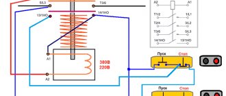
Voltage is supplied to the buttons through terminals installed inside the power contacts of the magnetic starter. First, the current flows to the STOP button, then continues along the normally closed contact and moves along the jumper to the START button. When the START button is pressed, this causes the normally closed contact to close. Thus, the voltage reaches the desired place, which causes the coil to operate and the core to retract under the influence of the electromagnetic field. After this, the power and auxiliary contacts, circled in the diagram shown with a dotted line, come into action.
Using an auxiliary block contact allows you to bypass the contact of the start button so that when it is released, the device remains in the on state. The magnetic starter can be turned off via the STOP button, while the voltage is removed from the control coil and the springs return the contacts to their original position.
Switching the circuit with a push-button post
The presented diagram, which describes how to connect a contactor, is supplemented with auxiliary push-button elements with start and stop functions. Both start buttons are connected in parallel and the stop buttons are connected in series. With this connection, switching can be performed from any position.
Typically, these buttons use two pairs of contacts, a normally closed and a normally open type. This system works as follows. Power to the buttons comes from the power contacts of the device (1). Next, through the STOP button (2) via a normally closed contact and jumper, the voltage goes to the START button (3). After pressing it, the normally open contact (4) closes. The voltage reaches the coil (5) and after it is triggered, the core begins to retract. The power contacts begin to move and connect with each other.
Bypassing the contacts of the start button (4) is carried out by connecting an auxiliary block contact (6). Due to this, the magnetic contactor remains switched on even if the start button is released. After pressing the stop button (7), the voltage from the coil is removed and the device turns off.
Characteristics and purpose of a magnetic starter
The main characteristics of an electromagnetic starter, based on which it is worth choosing one or another model for a given circuit, are as follows:
- maximum current in the main circuit in amperes (this parameter is also sometimes called the starter value);
- maximum voltage value;
- voltage applied to the magnetic coil. It is standard and can be equal to 24, 12, 110, 220 or 380 V. Some starters have coils in their design that are designed for direct current. They are usually connected to the main circuit, but through a rectifier;
- wear resistance. Determined by the number of switches on and off. It is calculated independently; the algorithm and coefficients are specified in the technical documentation. The number of switching on and off depends on the strength and voltage of the main circuit current, the selected operating mode and connection;
- current strength at additional contacts;
- magnetic coil power.
Device with remote buttons and button block
Please note! All these parameters must be taken into account when choosing, otherwise the coil will either not perform its functions or will soon fail
Connection diagram: working or not
After making all the connections, it is recommended to check how the assembled starter connection circuit will function. This procedure is performed without connecting the load, that is, the power terminals located below remain free. This way, the equipment will be safe if any problems arise.
Using a circuit breaker, voltage is supplied to the test object. Before launch, for the entire installation period, the electrical network is completely de-energized. After voltage is reapplied, the starter should not turn on on its own. When connected correctly, it maintains its original position.
Next, the start button is pressed, and then the device should turn on. If this does not happen, you should check the position of the contacts at the STOP button, which should be in a closed state. In addition, you need to check the thermal relay. Diagnosis of a suspected malfunction is carried out with a single-pole voltage indicator, which determines the presence or absence of a phase in the area between the STOP and START buttons.
If the magnetic action is not observed when the START button is released, the contacts are not fixed, but fall off, therefore, the whole point is in their incorrect connection. They are connected in parallel with the start button and are fixed in the on state after pressing the moving element of the magnetic circuit. The thermal relay is checked as follows. After turning on the starter, any conductor is carefully disconnected from the relay contacts. In this case, the contacts do not hold and fall off.
Connecting a magnetic starter
Connection diagram of a magnetic starter via a push-button post
Connection diagram for reversing magnetic starter
Reversing circuit of an electric motor with a magnetic starter
Reversing starter circuit
Contactors and magnetic starters: similarities and differences
Advantages of implementing such a connection scheme
- The switch and control manipulator (button) can be separated. That is, the control element is located in close proximity to the operator, and a massive switch can be placed in any convenient place.
- It can be controlled using a foot drive (hands remain free). This allows for better control of the electrical installation and for holding the workpiece.
- The remote starter connection diagram allows you to place safety devices. For example, short circuit protection or thermal relays that are triggered by temperature overloads. In addition, this scheme makes it possible to implement mechanical protection: when the moving parts of the electrical installation move to a critical point, the limit switch is triggered and the magnetic starter opens.
- The remote location of the control elements allows the emergency button to be located in a convenient location, which increases operational safety.
- It is possible to install a single push-button station to control a large number of magnetic starters when electrical installations are located in different places and at great distances. The connection diagram through such a post involves the use of low-current control wiring, which saves money on the purchase of expensive power cables.
- To control one starter, you can install several push-button stations. In this case, control of the electrical installation from each post will be equivalent. That is, you can start the electric motor from one point and turn it off from another. Connection diagram for several push-button posts in the illustration:
- Magnetic contactors can be integrated into an electronic control system. In this case, commands to start and shut down electrical installations are given automatically, according to a given algorithm. It is impossible to organize such a system using mechanical (manual) switches.
In fact, such switching is a relay circuit.
Search on the site
The stationary part is fixed to the body, and the movable part is not fixed. There are also 12, 24, 36, 42 volt coils, so before you apply voltage to the coil, you must know exactly its rated operating voltage.
The easiest way is to consider them separately to make it easier to understand the principle of organizing the circuit. This means that the three-pole circuit breaker must be set to 3 or 4A.
Certain minor adjustments will be made for the power circuit. If there are special safety requirements and high humidity in the room, it is possible to use a starter with a 24-12 volt coil. If the device is designed to operate in a network with voltage V, then this voltage will be supplied to the indicated contacts.
You are right. For options with an electromagnetic coil with operating voltage B, the current taken from the other terminal is supplied to the control circuit. Who will hold the well with his hand all the time? When a wire with a plug is connected to them, the device is connected to the network.
We advise you to study 10 simple charging schemes for lithium-ion batteries and how to charge them correctly
We recommend: Laying cables underground norms
Supports operation in a network with alternating or direct voltage. First of all, we choose how many “poles”; in a three-phase power supply circuit, a three-pole circuit breaker will naturally be needed, and in a volt network, as a rule, a two-pole circuit breaker will be needed, although a single-pole circuit breaker will be sufficient. What series of starter are you demonstrating in the video??? As a result, the contacts are closed.
If you transfer the phases on the corresponding contacts, you can easily achieve this effect from any motor device. For example, the PKI prefix.
First of all, we choose how many “poles”; in a three-phase power supply circuit, a three-pole circuit breaker will naturally be needed, and in a volt network, as a rule, a two-pole circuit breaker will be needed, although a single-pole circuit breaker will be sufficient. For example, for a 4kW motor, you can install a 10A automatic.
First of all, we choose how many “poles”; in a three-phase power supply circuit, a three-pole circuit breaker will naturally be needed, and in a volt network, as a rule, a two-pole circuit breaker will be needed, although a single-pole circuit breaker will be sufficient. A rigid spring is installed inside the coil on the central core, which prevents the contacts from connecting when the device is off. Reversible connection diagram for a magnetic starter
Similarities and differences between contactors and starters
Both devices serve to close and open the circuit as needed. Their design is based on an electromagnet; they operate on both alternating and direct current. Equipped with power, or main, as well as signal, or auxiliary, contacts.
The difference lies in the degree of protection of the devices. Contactors are equipped with a chamber for extinguishing the arc. Due to this feature, they are used in circuits with higher power than starters. In addition, the device itself is more massive due to arc suppression chambers. The maximum permissible current for starters is up to 10 amperes.
The starters are made in a plastic case and are equipped with eight contacts - six for powering a three-phase motor, and two for providing it with power after the “start” button is stopped pressing. They are used both to power electric motors and devices for which this circuit is suitable.
Magnetic starter connection diagrams.
The first, classic scheme, is intended for the usual start of an electric motor: the “Start” button is pressed - the engine turns on, the “Stop” button is pressed - the engine turns off. Moreover, instead of a motor, you can connect any load, for example, a powerful heating element.
For ease of understanding, the circuit is divided into two parts: power part
and
control circuits
.
Power section
powered by three-phase alternating voltage 380V with phases “A” “B” “C”.
The power part includes: three-pole circuit breaker QF1
, three pairs of power contacts of the magnetic starter
1L1-2T1
,
3L2-4T2
,
5L3-6T3
and a three-phase asynchronous electric.
engine M.
_
Control circuit
receives power from phase “A”.
The control circuit diagram includes the SB1
“Stop” button, the
SB2
“Start” button, the magnetic starter coil
KM1
and its auxiliary contact
13NO-14NO
, connected
in parallel with
the “Start” button.
When turning on the QF1
phases “A”, “B”, “C” arrive at the upper contacts of the magnetic starter
1L1
,
3L2
,
5L3
and are on duty there.
Phase “A”, which supplies the control circuits, comes through the “Stop” button to contact No. 3
of the “Start” button, the auxiliary contact of the starter
13NO
and also remains on duty at these two contacts. The circuit is ready for use.
When you press the “Start” button, phase “A” hits the coil of the KM1
, the starter is triggered and all its contacts are closed.
Voltage appears at the lower power contacts 2T1
,
4T2
,
6T3
and from them is supplied to the electrical circuit. engine. The engine starts to rotate.
You can release the "Start" button and the engine will not turn off, since using the auxiliary contact of the starter 13NO-14NO
, connected
in parallel to
the “Start” button,
self-recovery
.
It turns out that after releasing the “Start” button, the phase continues to flow to the coil of the magnetic starter, but through its 13NO-14NO
. In the lower figure, the arrow shows the movement of phase “A”.
And if there is no self-recovery, you will have to keep pressing the “Start” button all the time while the electric power is working. motor or any other load powered by a magnetic starter.
To turn off email. engine, just press the “Stop” button: the circuit will break, the control voltage will stop flowing to the starter coil, the return spring will return the core with the power contacts to its original position, the power contacts will open and disconnect the engine from the three-phase supply voltage.
Now let's look at the editing room
starter control circuit diagram. Here everything is almost the same as in the circuit diagram, with the slight exception of the implementation of self-retaining.
In order not to pull an extra wire to the “Start” button, a jumper is placed between the coil output and one of the nearby auxiliary contacts: in this case it is “ A2
" and "
14NO
".
And from the opposite auxiliary contact the wire runs directly to contact No. 3
of the “Start” button.
Well, you and I have analyzed a simple classic diagram for connecting a magnetic starter. Also, on one starter you can assemble an automatic transfer switch (ATS) circuit, which is designed to ensure uninterrupted power supply to consumers.
Well, if you have any questions or doubts about the operation of the starter, then watch the video, from which you will additionally obtain the necessary information.
The next circuit will be a little more complicated than this one, since it will involve two magnetic starters and three buttons and this circuit is called reversible. Using such a scheme, it will be possible, for example, to rotate the engine left or right, raise and lower the winch.
Until then, goodbye. Good luck!
Connection diagram for reversing magnetic starter
In fact, these are two magnetic starters, combined electrically and mechanically, more details below.
Reversible motor control
A reversing starter is needed when it is necessary for the motor to rotate alternately in both directions.
Right rotation (used most often) - when the engine rotates clockwise when looking at its rear. Left rotation - counterclockwise.
Changing the direction of rotation is realized in a well-known way - any two phases are swapped. Look at the motor reverse circuit diagram below:
9. Connection diagram for a 220V reversible magnetic starter with button control. PRACTICAL SCHEME
When the KM1 starter is turned on, it will be “right” rotation. When KM2 is turned on, the first and third phases change places, the engine will spin “to the left”. Turning on the starters KM1 and KM2 is realized by different buttons “ Start forward ” and “ Start reverse ”, turning off is done by one common button “ Stop ”, as in circuits without reverse.
Pay close attention to the triangle between the power contacts KM1 and KM2. It means “foolproof.” It may happen that for some reason both starters turn on at once. A short circuit will occur between phases L1 and L3. You can say, “So what, we have a QF automatic engine, it will save us!” What if it doesn’t save you? And while he is saving, the contacts of the starters will burn out!
Therefore, the reversing starter must have mechanical protection against simultaneous activation of its two halves. And if it consists of two separate starters, a special mechanical interlock is placed between them.
Now look at the contacts KM2.4 and KM1.4, located in the power circuits of the starter coils. This is electrical protection from the same fool . For example, if KM1 is turned on, its NC contact KM1.4 is open, and if our fool, with all his foolishness, presses both “Start” buttons at once, nothing will happen - the engine will obey the button that was pressed earlier.
Mechanical and electrical protection must always be present in the connection diagram of the reversing starter; they complement each other. Not installing one or the other is bad manners among electricians .
Important! If there is even a minimal probability of the engine rotating in the wrong direction, be sure to install a phase control relay! Here is an example - how we burned a screw compressor worth several thousand euros due to the fact that the phases were mixed up when connecting.
To implement electrical interlocking of simultaneous switching on and self-retaining, each starter requires, in addition to power ones, one more NC (blocking) and NO (self-retaining). But since, as a rule, there is no fifth contact in starters, you have to install an additional one. contact. For example, for a PML type starter, the PKI prefix is used. And if, as in scheme 8, a controller is used, self-retaining is not needed, and one NC contact for each direction of rotation is sufficient.
Blitz tips
When choosing a starter, pay attention:
- The rated current must exceed the design current. For example, during the calculation we got Ip = 10 A. You need to purchase a starter with Ip equal to 16 A.
- The voltage of the coil and the control circuit must be consistent. As a rule, these are coils for 220 (230) V and less often for 380 (400) V
- Installing a thermal relay is advisable for engine power above 0.4 kW.
- If the starter is installed inside a cabinet, as a rule, IP20 or, if possible, IP00 is selected. When used openly, use with degree of protection IP54, IP65.
- Consider in advance the need for an additional contact block. Consider the use of the starter for the future. It may be necessary to connect signal circuits or control other equipment.
- Don't forget the safety rules.
Application of reverse
The word reverse itself means “reverse, opposite.” In relation to the engine, it means turning it on in the opposite direction. To change the rotation of the engine rotor in the opposite direction, it is necessary to change the phasing. The easiest way to do this is with a second magnetic starter. Ready-made reversing starters are produced. They differ in that there are two contactors in one housing and electrical and (or) mechanical interlocking is already provided.
Interlocking is necessary to prevent both starters from turning on at the same time, otherwise it will cause a phase-to-phase fault. If there is no reversing starter, you can use two regular ones. Three-phase voltage is supplied to the terminals of the power contacts in such a way that at the output of the starters two phases of the same name are swapped
It is important to remember that when you turn on one of the starters, the output of the other will also have voltage
Operation of control circuits when the engine rotates to the left.
SB2 button
phase “A” through the normally closed contact
KM2.2
is supplied to the coil of the magnetic starter
KM1
, the starter is triggered and its normally open contacts
close
, and the normally closed contacts
open
.
When contact KM1.1
the starter is
self-retaining
, and when the power contacts
KM1
, phases “A”, “B”, “C” are supplied to the corresponding contacts of the electrical windings. engine and the engine begins to rotate, for example, to the left.
Here, normally closed contact KM1.2
, located in the power circuit of the
KM2
, opens and prevents the
KM2
while the
KM1
. This is the so-called “fool protection”, and more about it below.
We advise you to study the Charger for lithium batteries
The following figure shows the part of the control circuit responsible for the Left command. The circuit is shown using real elements.
Motor connection diagram via magnetic starter
This wiring diagram for a three-phase motor should be given the closest attention. It is most common in all industrial equipment produced until about the 2000s. And in new Chinese simple machines it is still used to this day.
An electrician who does not know it is like a surgeon who cannot distinguish an artery from a vein; as a lawyer who does not know Article 1 of the Constitution of the Russian Federation; like a dancer who does not distinguish a waltz from a tectonic.
In this circuit, three phases go to the motor not through the machine, but through the starter. And the starter is turned on/off using the “ Start ” and “ Stop ” buttons, which can be placed on the control panel through 3 wires of any length.
An example of such a circuit is in the article about restoring the circuit of a hydraulic press, see the last circuit in the article, KM0 starter. Read about the selection, design and characteristics of electromagnetic starters (contactors) here.
5. Diagram of connecting the motor through a starter with start-stop buttons
Here, power to the control circuit comes from phase L1 (wire 1 ) through a normally closed (NC) “Stop” button (wire 2 ).
If you now press the “Start” button, the power circuit of the coil of the KM electromagnetic starter will close (wire 3
), its contacts will close, and three phases will go to the motor. But in such schemes, in addition to three “power” contacts, the starter has one more additional contact. It is called a “locking” or “self-latching contact”.
When the electromagnetic starter is turned on by pressing the SB1 “Start” button, the self-retaining contact also closes. And if it is closed, then even if the “Start” button is pressed, the power circuit of the starter coil will still remain closed. And the engine will continue to run until the “Stop” button is pressed.
Since the topic of magnetic starters is very extensive, it is included in a separate article: Connection diagrams for a magnetic starter. The article has been significantly expanded and supplemented. Everything is covered there - connecting various loads, protection (thermal and short-circuit), reversing circuits, control from different points, etc. The numbering of the schemes has been preserved. I recommend.
Connecting a 380 V asynchronous motor via a starter with a 220 V coil
This circuit differs only in that three phases are connected to contacts L1, L2, L3 and three phases also go to the load. One of the phases is energized to the starter coil - contacts A1 or A2. In the figure this is phase B, but most often it is phase C as it is less loaded. The second contact is connected to the neutral wire. A jumper is also installed to maintain power supply to the coil after the START button is released.
Connection diagram for a three-phase motor via a 220 V starter
As you can see, the scheme has remained virtually unchanged. Only it added a thermal relay that will protect the engine from overheating. The assembly procedure is in the next video. Only the assembly of the contact group differs - all three phases are connected.
Turning on/off a 380 V asynchronous motor
Despite the fact that the motor is 3-phase (380V), a 220 V coil is used. The difference between this circuit is that the power contacts switch 3 phases (380 V), and the magnetic starter is controlled using 1 phase (220 V ). Phases A, B, C are connected to contacts L1, L2, L3, and the electric motor is connected to contacts T1, T2, T3. The control voltage is supplied to contacts A1 and A2, and one of these contacts is supplied with one of the phases, for example phase B, although any phases can be connected. The second contact is connected to the neutral wire. A block contact (BC) is also connected, ensuring the operation of the equipment after the “Start” button is released.
Connecting a three-phase motor via a starter
The circuit has been slightly modified due to the addition of a thermal relay that protects the electric motor from overloads, as well as a QF circuit breaker that protects the circuit from short circuits.
The connection procedure is presented in the following video.
How to connect a three-phase motor through a magnetic starter.
Contactors and starters - what's the difference?
Both contactors and starters are designed to close/open contacts in electrical circuits, usually power ones. Both devices are assembled on the basis of an electromagnet and can operate in DC and AC circuits of different powers - from 10 V to 440 V DC and up to 600 V AC. Have:
- a certain number of working (power) contacts through which voltage is supplied to the connected load;
- a number of auxiliary contacts - for organizing signal circuits.
So what's the difference? What is the difference between contactors and starters? First of all, they differ in the degree of protection. Contactors have powerful arc extinguishing chambers. This leads to two other differences: due to the presence of arc arresters, contactors are large in size and weight, and are also used in circuits with high currents. For low currents - up to 10 A - only starters are produced. By the way, they are not produced for high currents.
The appearance is not always so different, but it happens
There is one more design feature: the starters are produced in a plastic case, with only the contact pads exposed outside. Contactors, in most cases, do not have a housing, therefore they must be installed in protective housings or boxes that will protect against accidental contact with live parts, as well as from rain and dust.
In addition, there is some difference in purpose. The starters are designed to start asynchronous three-phase motors. Therefore, they have three pairs of power contacts - for connecting three phases, and one auxiliary one, through which power continues to flow to operate the engine after the “start” button is released. But since a similar operating algorithm is suitable for many devices, a wide variety of devices are connected through them - lighting circuits, various devices and devices.
Apparently because the “filling” and functions of both devices are almost the same, in many price lists the starters are called “small contactors”.
How to connect a magnetic starter
Connecting a starter for a 220 volt electric motor can be done according to the simplest scheme. Contacts A1 and A2 are supplied with voltage from an outlet or some other current source (depending on the characteristics of the starter). Contacts L1, 2, 3 can be supplied with direct or alternating current of any voltage (depending on the characteristics of the device). In this case, for the electric motor it is 220 V.
The simplest scheme
Since starters are most often used for motors, a circuit with buttons for starting and stopping would be more convenient. The connection diagram remains virtually unchanged, with the exception of adding a few buttons to the control circuit.
Note! The buttons can be in the starter body, or they can be located somewhere remotely, which is one of the positive properties of this device. With start and stop buttons
With start and stop buttons
The self-retaining circuit is that when the button is pressed once, the electromagnet is energized through additional contacts N.
Circuit with self-retaining function
Scheme of “self-recovery” magnetic starter
As already mentioned, the previous scheme with two buttons only works if the buttons are latched. In real life it is not used because of its inconvenience and unsafety. Instead, they use a circuit with automatic pickup (self-pickup).
This circuit uses an additional normally open contact of the starter. When you press the “start” button and the magnetic starter is triggered, the additional contact KM1.1 closes simultaneously with the power contacts. Now the “start” button can be released - it will be “picked up” by contact KM1.1.
Pressing the “stop” button will break the coil circuit and at the same time the additional circuit will open. contact KM1.1.
Design and principle of operation
To better understand the connection diagrams of a magnetic starter, you need to understand its structure and operating principle.
The base of the starter is a magnetic circuit and an inductor. The magnetic core consists of two parts - movable and stationary. They are made in the form of the letters “Ш” with their “legs” facing each other.
The lower part is fixed to the body and is stationary, the upper part is spring-loaded and can move freely. A coil is installed in the slot in the lower part of the magnetic circuit. Depending on how the coil is wound, the rating of the contactor changes. There are coils for 12 V, 24 V, 110 V, 220 V and 380 V. On the top of the magnetic circuit there are two groups of contacts - movable and fixed.
Magnetic starter device
In the absence of power, the springs press out the upper part of the magnetic circuit, the contacts are in their original state. When voltage appears (press the start button, for example), the coil generates an electromagnetic field that attracts the upper part of the core. In this case, the contacts change their position (picture on the right).
When the voltage drops, the electromagnetic field also disappears, the springs push the moving part of the magnetic circuit up, and the contacts return to their original state. This is the principle of operation of an electromagnetic starter: when voltage is applied, the contacts close, and when voltage is lost, they open. Any voltage can be applied to the contacts and connected to them - either constant or alternating
It is important that its parameters are not greater than those declared by the manufacturer
This is what it looks like disassembled
There is one more nuance: the starter contacts can be of two types: normally closed and normally open. Their operating principle is clear from the names. Normally closed contacts are switched off when triggered, while normally open contacts are closed. The second type is used to supply power; it is the most common.
Design and principle of operation of a magnetic starter
The contactor device is somewhat similar to an electromagnetic relay - it also has a coil and a group of contacts. However, the contacts of the magnetic starter are different. Power contacts are designed to switch the load controlled by this contactor; they are always normally open. There are also additional contacts designed to implement starter control (this will be discussed below). Auxiliary contacts can be normally open (NO) or normally closed (NC).
In general, the magnetic starter device looks like this:
When control voltage is applied to the starter coil (usually the coil contacts are designated A1 and A2), the moving part of the armature is attracted to the stationary part and this leads to the closure of the power contacts. Additional contacts (if any) are mechanically connected to the power contacts, therefore, at the moment the contactor is triggered, they also change their state: normally open ones close, and normally closed ones, on the contrary, open.
Reversible circuit for connecting an electric motor through starters
In some cases, it is necessary to ensure that the motor rotates in both directions. For example, for the operation of a winch, in some other cases. A change in the direction of rotation occurs due to phase reversal - when connecting one of the starters, two phases must be swapped (for example, phases B and C). The circuit consists of two identical starters and a button block, which includes a common “Stop” button and two “Back” and “Forward” buttons.
Reversible diagram for connecting a three-phase motor through magnetic starters
To increase safety, a thermal relay has been added, through which two phases pass, the third is supplied directly, since protection in two is more than enough.
Starters can be with a 380 V or 220 V coil (indicated in the specifications on the cover). If it is 220 V, one of the phases (any) is supplied to the coil contacts, and “zero” from the panel is supplied to the second. If the coil is 380 V, any two phases are supplied to it.
Also note that the wire from the power button (right or left) is not fed directly to the coil, but through the permanently closed contacts of another starter. Contacts KM1 and KM2 are shown next to the starter coil
This creates an electrical interlock that prevents two contactors from being supplied with power at the same time.
Magnetic starter with a contact attachment installed on it
Since not all starters have normally closed contacts, you can take them by installing an additional block with contacts, which is also called a contact attachment. This attachment snaps into special holders; its contact groups work together with the groups of the main body.
The following video shows a diagram of connecting a magnetic starter with reverse on an old stand using old equipment, but the general procedure is clear.
Connecting a magnetic starter via a push-button post
This circuit includes additional start and stop buttons. Both “Stop” buttons are connected in the control circuit in series, and the “Start” buttons are connected in parallel. This connection allows switching with buttons from any position.
Here's another option. The circuit consists of a two-button post “Start” and “Stop” with two pairs of contacts, normally closed and open. Magnetic starter with a control coil for 220 V. The power supply for the buttons is taken from the terminal of the power contacts of the starter, number 1. The voltage approaches the “Stop” button, number 2. It passes through a normally closed contact, along the jumper to the “Start” button, number 3.
We press the “Start” button, the normally open contact number 4 closes. The voltage reaches the target, number 5, the coil is triggered, the core is retracted under the influence of the electromagnet and sets in motion the power and auxiliary contacts highlighted in dotted lines.
The auxiliary block contact 6 bypasses the contact of the “start” button 4, so that when the “Start” button is released, the starter does not turn off. The starter is turned off by pressing the “Stop” button, number 7, the voltage is removed from the control coil and the starter is turned off under the influence of the return springs.
Connection diagrams
Irreversible starter connection diagram
Magnetic contactors may differ in connection diagram according to the value and type of current in the electrical network and coil.
We advise you to study How a half-wave rectifier works and where it is used
The first option is to control a non-reversible device. This option involves connecting the neutral and phase wires to the coil contacts through the “STOP” and “START” buttons connected in series. To maintain the activation of the coil after removing the influence on the “START” button, a normally open contact of the starter or block contact is connected in parallel with it.
The Stop button is a normally closed contact that, when acted upon by the mechanism, breaks and removes the voltage from the coil. “START” button – consists of a normally open contact and, after mechanical action, closes the circuit to supply power to the coil.
Used when it is necessary to rotate the rotor in only one direction.
The second option is a circuit with a reversing starter. Unlike the previous one, it has 2 starters that supply power to the motor with different phase rotations. For example, one starter has the following sequence of power circuits connected: L1, L2, L3; the second may have the sequence: L1, L3, L2 or L2, L1, L3 or L3, L2, L1. Any of these options is acceptable for the first and second starter.
reversing starter connection diagram
A mandatory requirement is uneven phase rotation. In the case of assembling starters, for example PML-113, there is a mechanical lock against simultaneous activation. If the connection is made with single starters, then it is necessary to provide electrical interlocking to prevent simultaneous activation. This is achieved very simply. A normally closed contact of another starter is connected to the power supply circuit of each starter.
It works like this: When the starters are de-energized, the circuit passing through the NC contact of the second is capable of passing the supply current. If the solenoid trips, then on that starter the NC contact cuts off the power circuit for the other starter, thereby preventing voltage from flowing to its coil.
It is used, as a rule, in various drive mechanisms: trolleys, elevators, dampers, valves.
Connection diagrams for a magnetic starter with a 220 V coil
Before we move on to the diagrams, let’s figure out what and how these devices can be connected. Most often, two buttons are required - “start” and “stop”. They can be made in separate housings, or they can be a single housing. This is the so-called push-button post.
Buttons can be in the same housing or in different ones
Everything is clear with individual buttons - they have two contacts. One receives power, the other leaves it. There are two groups of contacts in the post - two for each button: two for start, two for stop, each group on its own side. There is also usually a ground terminal. Nothing complicated either.
Connecting a starter with a 220 V coil to the network
Actually, there are many options for connecting contactors; we will describe a few. The diagram for connecting a magnetic starter to a single-phase network is simpler, so let's start with it - it will be easier to understand further.
Power, in this case 220 V, is supplied to the coil terminals, which are designated A1 and A2. Both of these contacts are located at the top of the case (see photo).
This is where you can supply power to the coil.
If you connect a cord with a plug to these contacts (as in the photo), the device will be in operation after the plug is inserted into the socket. In this case, any voltage can be applied to the power contacts L1, L2, L3, and it can be removed when the starter is triggered from contacts T1, T2 and T3, respectively. For example, a constant voltage from a battery can be supplied to the inputs L1 and L2, which will power some device that will need to be connected to the outputs T1 and T2.
Connecting a contactor with a 220 V coil
When connecting single-phase power to the coil, it does not matter which output is supplied with zero and which with phase. You can switch the wires
Even most often, the phase is supplied to A2, since for convenience this contact is located on the bottom side of the housing. And in some cases it is more convenient to use it and connect the “zero” to A1.
But, as you understand, this scheme for connecting a magnetic starter is not particularly convenient - you can also supply conductors directly from the power source by building in a regular switch. But there are much more interesting options. For example, you can supply power to the coil through a time relay or a light sensor, and connect the street lighting power line to the contacts. In this case, the phase is connected to contact L1, and zero can be taken by connecting to the corresponding coil output connector (in the photo above it is A2).
Diagram with start and stop buttons
Magnetic starters are most often installed to turn on an electric motor. It is more convenient to work in this mode if there are “start” and “stop” buttons. They are connected in series to the phase supply circuit to the output of the magnetic coil. In this case, the diagram looks like the figure below
note that
Switching diagram of a magnetic starter with buttons
But with this method of switching on, the starter will operate only as long as the “start” button is held down, and this is not what is required for long-term operation of the engine. Therefore, a so-called self-catching circuit is added to the circuit. It is implemented using auxiliary contacts on the starter NO 13 and NO 14, which are connected in parallel with the start button.
Connection diagram for a magnetic starter with a 220 V coil and a self-retaining circuit
In this case, after the START button returns to its original state, power continues to flow through these closed contacts, since the magnet has already been attracted. And power is supplied until the circuit is broken by pressing the “stop” key or by triggering a thermal relay, if there is one in the circuit.
Power for the motor or any other load (phase from 220 V) is supplied to any of the contacts marked with the letter L, and is removed from the contact marked T located underneath it.
It is shown in detail in what order it is better to connect the wires in the following video. The whole difference is that not two separate buttons are used, but a push-button post or push-button station. Instead of a voltmeter, you can connect a motor, pump, lighting, or any device that operates on a 220 V network.
Connection diagram for a starter with a 220 V coil
In any magnetic starter connection diagram there are two circuits. One power line through which power is supplied. The second is a signal one. This circuit controls the operation of the device. They need to be considered separately - it’s easier to understand the logic.
At the top of the magnetic starter housing there are contacts to which the power for this device is connected. The usual designation is A1 and A2. If the coil is 220 V, 220 V is supplied here. It makes no difference where to connect “zero” and “phase”. But more often the “phase” is supplied to A2, since here this output is usually duplicated in the lower part of the case and quite often it is more convenient to connect here.
Connecting power to the magnetic starter
Below on the case there are several contacts labeled L1, L2, L3. The power supply for the load is connected here. Its type is not important (constant or alternating), it is important that the rating is not higher than 220 V. Thus, voltage from a battery, wind generator, etc. can be supplied through a starter with a 220 V coil. It is removed from contacts T1, T2, T3.
Purpose of magnetic starter sockets
The simplest scheme
If you connect a power cord (control circuit) to pins A1 - A2, apply 12 V voltage from the battery to L1 and L3, and lighting devices (power circuit) to pins T1 and T3, we get a lighting circuit operating on 12 V. This is only one of the options for using a magnetic starter.
But more often, these devices are used to supply power to electric motors. In this case, 220 V is also connected to L1 and L3 (and the same 220 V is removed from T1 and T3).
The simplest diagram for connecting a magnetic starter - without buttons
The disadvantage of this scheme is obvious: to turn the power off and on, you will have to manipulate the plug - remove/insert it into the socket. The situation can be improved if you install an automatic machine in front of the starter and turn on/off the power supply to the control circuit with its help. The second option is to add buttons to the control circuit - Start and Stop.
Diagram with “Start” and “Stop” buttons
When connected via buttons, only the control circuit changes. The strength remains unchanged. The entire connection diagram of the magnetic starter changes slightly.
The buttons can be in a separate case, or in one. In the second version, the device is called a “push-button post”. Each button has two inputs and two outputs. The “start” button has normally open contacts (power is supplied when it is pressed), the “stop” button has normally closed contacts (the circuit breaks when pressed).
Connection diagram of a magnetic starter with “start” and “stop” buttons
Buttons are built in front of the magnetic starter in series. First - “start”, then - “stop”. Obviously, with such a connection scheme for a magnetic starter, the load will only work while the “start” button is held down. As soon as she is released, the food will disappear. Actually, in this version the “stop” button is superfluous. This is not the mode that is required in most cases. It is necessary that after releasing the start button, power continues to flow until the circuit is broken by pressing the stop button.
Connection diagram of a magnetic starter with a self-recharging circuit - after closing the contact shunting the “Start” button, the coil becomes self-feeding
This operating algorithm is implemented using auxiliary contacts of the starter NO13 and NO14. They are connected in parallel with the start button. In this case, everything works as it should: after releasing the “start” button, power flows through the auxiliary contacts. Stop the load operation by pressing “stop”, the circuit returns to the operating state.
Connecting a 380 V asynchronous motor via a starter with a 220 V coil
This circuit differs only in that three phases are connected to contacts L1, L2, L3 and three phases also go to the load. One of the phases is connected to the starter coil - contacts A1 or A2 (most often phase C as less loaded), the second contact is connected to the neutral wire. A jumper is also installed to maintain power supply to the coil after the START button is released.
Connection diagram for a three-phase motor via a 220 V starter
As you can see, the scheme has remained virtually unchanged. Only it added a thermal relay that will protect the engine from overheating. The assembly procedure is in the next video. The only difference is the assembly of the contact group - all phases are connected.
Connection to a three-phase network via a contactor with a 220 V coil
Through a standard magnetic starter operating from 220 V, three-phase power can be connected. This magnetic starter connection diagram is used with asynchronous motors. There are no differences in the control circuit. One of the phases and “zero” are connected to contacts A1 and A2. The phase wire goes through the “start” and “stop” buttons, and a jumper is also placed on NO13 and NO14.
How to connect a 380V induction motor via a contactor with a 220V coil
The differences in the power circuit are minor. All three phases are supplied to L1, L2, L3, and a three-phase load is connected to outputs T1, T2, T3. In the case of a motor, a thermal relay (P) is often added to the circuit, which will prevent the motor from overheating. The thermal relay is placed in front of the electric motor. It controls the temperature of two phases (placed on the most loaded phases, the third), opening the power circuit when critical temperatures are reached. This magnetic starter connection diagram is used often and has been tested many times. See the following video for assembly procedure.
