Source:
|
The phrase two-color LED indicates that such a chip glows in two colors. This type of light source has 2 multi-colored crystals and 2 or 3 leads. The design is similar to RGB, but the operating principle is different - one crystal lights up if the current flows in one direction, the second - when the polarity changes. This feature is used in indicators and alarm systems of various electrical equipment.
Characteristics of two-color diodes with two and three outputs
A two-color diode contains 2 crystals connected in counter-parallel. The case has standard DIP and SMD sizes with two or three pins. In the first option, each terminal serves as the anode of one crystal and the cathode of another. Such a source emits 2 or 3 colors. The third is obtained by simultaneous glow of both crystals.
Possible color combinations:
- Red and blue;
- red and green;
- red and yellow or yellow-green;
- blue and yellow;
- green and yellow.
The voltage drop depends on the color of the crystal:
- red 1.6 V;
- green 1.8 V;
- blue 3.5 V;
- yellow 1.7 V.
Important! A two-color LED can always be replaced with two chips of different colors connected according to the appropriate circuit.
If a two-color LED has 2 pins, the crystals are connected back-to-back. In a design with a common anode or cathode, 2 LEDs of different colors are installed.
In chips with two pins, the common contact is most often located in the middle of the package, but there are exceptions. You can determine the polarity using an ohmmeter.
The colors of the crystals are selected in accordance with the rules of ergonomics. Green color most often indicates normal operation of the equipment, red indicates an emergency situation. The color yellow is used to identify standby mode. Blue crystals are used to highlight surfaces of dark shades.
How to properly connect a two-color LED?
LEDs are electronic components of different sizes and colors that are enclosed in a transparent housing. The epoxy resin lenses are the LED body, the crystals are the light source, the long lead is the anode, and the short lead is the cathode. It is impossible to immediately determine what kind of glow the lamps will have. The lamps begin to glow when the current flows in the forward direction. The intensity of the glow is proportional to the electric current.
Each light-emitting diode, according to all the laws of physics, must produce only one color. It depends on the material from which the semiconductor is made. No changes occur during operation. How then is a two-color LED created? What about multicolor?
Description of two-color LEDs
A two-color LED is two separate light emitters combined on one chip and made from different semiconductor alloys. This LED produces at least two colors. Since its body is made of special light-diffusing plastic, two light emitters working simultaneously create a third color.
Taking into account the peculiarities of human perception of color mixtures, the following combinations are most often used in a 2-color LED:
- red – yellow-green;
- red – blue or green
- Red Yellow;
- yellow green;
- yellow – yellow-green.
Also, the 2-color LED can be divided into several types:
- bi-color LED with two terminals, having a back-to-back connection;
- a two-color LED with three terminals, which are two separate emitters with a common cathode or a two-color LED with a common anode.
One LED housing can contain different lamps: red-yellow, red-green, blue-yellow and others. A tri-color LED combines red, green and blue lamps in one housing.
The most common three-pin LED is with two LEDs of a green and a red lamp in one housing. Such LEDs are more in demand because their use provides a wider range of colors, which makes it possible to produce inexpensive lamps whose lamps are capable of changing light over a wide spectrum. Using a pulse modulator, by changing the glow intensity of each semiconductor, it is possible to change the tone of illumination for each diode. To prevent possible overload, a separate resistor is provided for each LED.
Scope of application of two-color LEDs
A 2-color LED is an integrated assembly with two light-emitting crystals on one substrate. Despite the rather limited emission spectrum, 2-color LEDs are widely used in:
- instrument making, as a two-color 5mm LED used as an indicator;
- advertising business to attract consumer attention;
- decorating rooms using the play of light;
- modern signaling equipment, such as a two-color LED flasher, traffic lights;
- car tuning;
These devices are widely used in alarm, indication and visual design systems. 2-color LED lighting is actively used in the creation of electronic displays and signs. In addition, a two-color LED is used as a rotation indicator for a DC motor, showing which direction it is rotating.
| Depending on production or decorative needs, an engineer or designer can use a specific set of 2-color light-emitting diodes to solve the problems they face. |
LED for 2 colors – these are two ordinary LEDs in one housing. It has two legs and each is simultaneously the cathode of an LED of one color and the anode of a different color. Therefore, the color of the lamps will depend on the direction in which the current flows through the two-color diode.
This LED requires only one resistor. Two-color LEDs are less popular than three-color LEDs.
An example of a 2-color LED is charging for a mobile device and a battery, when the indicator light glows red during charging, and after charging the battery the light changes to green.
In cars, LED lamps are used where 2 colors are required in the headlight, when one lamp simultaneously serves as a marker and a turn signal. The dimensions will be red, and the turn signals will be yellow.
How to connect a two-color LED?
Connecting LEDs to a circuit requires connecting a ballast resistor, which is built into modern LEDs. By limiting the current in the circuit, connecting the LED is possible with a network voltage of 220V.
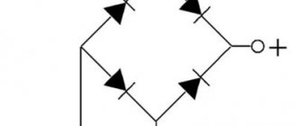
Standard LED switching circuit
The glow of the LED changes by 2 colors depending on which direction the current flows through the lamp. The device diagram is quite clear. It contains a resistor and two diodes connected opposite each other, which are connected in parallel. When current flows in the forward direction, one diode becomes locked and does not light up. When the current moves in the opposite direction, everything changes exactly the opposite.
After determining the LED current and voltage, you can calculate the resistance parameters that limit the current in the circuit. In the simplest circuit for switching on a two-color LED, a resistor limits the current. After calculating the resistance, its power is calculated. If you choose a low-power resistor, then there is a chance that it will soon fail. When connecting LEDs in series, one resistor connected to the circuit will suffice.
LEDs with different rated currents cannot be connected in series. To connect correctly, you need to understand that when connected in parallel, the current is summed, and when connected in series, the voltage is summed. Parallel and serial connection is possible only with identical LEDs using one resistor.
And if different LEDs are connected, then for reliability it is better to calculate each LED its own passive element of the electrical circuit.
Source: https://led-svetodiody.ru/info/dvuhcvetnyy-svetodiod
Operating principle of two-color LEDs
The operating principle of elements with two terminals is simple. The color of the glow changes simultaneously with the change in the polarity of the connection. This means that the color depends entirely on which path the current takes. When a plus is applied to one of the terminals, one crystal begins to glow, the second is locked. After changing the polarity, the locked one begins to glow, the luminous one is locked.
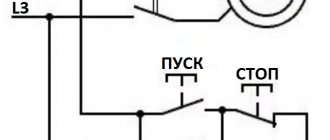
This circuit is used in indicators operating on alternating voltage. Two-color diodes are connected in parallel and counter, the current is limited by one resistor. Such elements are often mounted in push-button switches, with the help of which the color of the glow changes.
Since the color of the LEDs is unsaturated and dim, when mixed, a shade is formed that is difficult for humans to determine. Another feature is the change in shade when looking at the light source from different angles.
Standard LED switching circuit
The glow of the LED changes by 2 colors depending on which direction the current flows through the lamp. The device diagram is quite clear. It contains a resistor and two diodes connected opposite each other, which are connected in parallel. When current flows in the forward direction, one diode becomes locked and does not light up. When the current moves in the opposite direction, everything changes exactly the opposite.
After determining the LED current and voltage, you can calculate the resistance parameters that limit the current in the circuit. In the simplest circuit for switching on a two-color LED, a resistor limits the current. After calculating the resistance, its power is calculated. If you choose a low-power resistor, then there is a chance that it will soon fail. When connecting LEDs in series, one resistor connected to the circuit will suffice. LEDs with different rated currents cannot be connected in series. To connect correctly, you need to understand that when connected in parallel, the current is summed, and when connected in series, the voltage is summed. Parallel and serial connection is possible only with identical LEDs using one resistor. And if different LEDs are connected, then for reliability it is better to calculate each LED its own passive element of the electrical circuit.
Scope of application
The peculiarities of the emission spectrum do not prevent dual-illumination LEDs from finding a field of application.
LED indicators based on two-color diodes are used:
- in advertising;
- in signaling systems (traffic lights, flashing lights, signs, electronic displays);
- in electric motors (to determine the direction of rotation);
- when decorating premises;
- in phones, tablets, cameras;
- in charging various batteries;
- for car tuning.
Attention! A two-color lamp with an H7 socket is installed in the headlights of cars with low beam (white) and high beam (yellow), with a PY21W or P21W socket - in turn signals (red) and side markers (yellow).
In everyday life, you can make a garland from two-color LEDs. One color lights up during the positive half-cycle, the second - during the negative half-cycle.
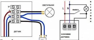
Connection diagrams for two-color LEDs
To make an electrical appliance with your own hands, you need to know how to connect a two-light LED. The simplest (but not entirely correct) option is to connect power to the legs through a resistor and determine the on/off cycles.
To add a resistor to the circuit, you need to calculate its resistance and power values.
Since 2015, GOST 29433-2014 has defined new power supply voltage parameters:
- nominal 230 V;
- minimum 207 V, under load 198 V;
- maximum 253 V.
The resistance of the resistor must be of such a value that the current necessary for the normal functioning of the two-color LED can flow through it, but the element does not overheat. Therefore, the rated current value of 20 mA for calculations is replaced by another value - 7 mA = 0.007 A, which allows the diode to glow normally.
Resistance:
You need to buy a 33 kOhm element.
Resistor power:
You need to buy a 2 W element.
To check, the current at maximum voltage is calculated:
Power:
This means that a 2 W resistor will not overheat even at the maximum network voltage.
Attention! If a two-color LED has 2 pins, it is connected using one resistor. If there are three terminals, 2 resistors are required, the resistance is calculated separately for each (the current is different for crystals with different colors).
On timer 555
The 555 timer is an integrated device that generates pulses at certain intervals. Models are available in plastic and metal DIP and SMD housings for 4.5 – 16 V. The main area of application in everyday life is the control of three-color strips and lamps. Timer 555 turns on the colors one by one. The standard supply voltage is 5 V, you can convert it to 12 V by changing the resistance of the resistors.
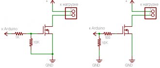
control circuit for two-color LEDs up to 1A
Control circuit for two-color LEDs on the controller
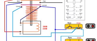
The control circuit for two-color LEDs is based on a TA7291P chip with two OUT outputs and two IN inputs. We connect two diodes or one two-color diode with a power of at least 1A to the output. If the logic at the inputs is the same, then the output potentials are equal, and accordingly the LED does not light up.
At different logical levels at the inputs, the microcircuit operates as follows. If one of the inputs, for example, IN1, has a low logical level, then the output OUT1 is connected to the common wire. The cathode of LED HL2 is also connected to the common wire through resistor R2. The voltage at the OUT2 output (if there is a logical one at the IN2 input) in this case depends on the voltage at the V_ref input, which allows you to adjust the brightness of the HL2 LED.
In this case, the voltage V_ref is obtained from PWM pulses from the microcontroller using the integrating chain R1C1, which regulates the brightness of the LED connected to the output. The microcontroller also controls the inputs IN1 and IN2, which allows you to obtain a wide variety of shades of light and LED control algorithms. The resistance of resistor R2 is calculated based on the maximum permissible current of the LEDs.
Main conclusions
Radio amateurs use two-color LEDs in various homemade lighting devices:
- “Electronic heart” with a 555 timer and a generator for decorating rooms during various celebrations;
- railway crossing models;
- brightness regulators for LED products;
- blinking regulators;
- “Roulette” (rotating circle) based on timer 555;
- 3 D cubes based on 4020 chip;
- turn signals for motorcycles mounted on a helmet;
- linear lamps for illuminating plants.
At home, any device should be designed so that one basic color is constantly illuminated. Most often it is green, indicating that it is connected to power. Another option is to install each diode in a separate place and enter a mode that includes a total glow.
If you make lamps from two-color diodes, you need to know that independent installation can lead to an unexpected spectrum of light. If the light source burns out, the entire system will have to be rebuilt.