If in the asynchronous machines discussed above the rotor had a rotation frequency different from the rotation frequency of the stator magnetic field, then in synchronous machines these frequencies are equal to each other. Synchronous machines can operate either as generators or as motors. Depending on the type of drive, synchronous generators received their names. Turbogenerator
, for example, is a generator driven by a steam turbine, a hydrogenerator rotates a water wheel, and a diesel generator is mechanically connected to an internal combustion engine. Synchronous motors are widely used to drive powerful compressors, pumps, and fans. Synchronous micromotors are used to drive tape mechanisms of recording devices, tape recorders, etc.
6.1. DESIGN AND PRINCIPLE OF OPERATION OF A SYNCHRONOUS GENERATOR
The stator of a synchronous machine is no different in design from the stator of an asynchronous motor. Three-phase, two-phase or single-phase windings are placed in the stator slots. A noticeable difference is the rotor, which is fundamentally a permanent magnet or electromagnet. This imposes special requirements on the geometric shape of the rotor. Any magnet has poles, the number of which can be two or more. In Fig. 6.1.1 shows two designs of generators, with a low-speed and a high-speed rotor.
As a rule, turbogenerators are high-speed. The number of pairs of magnetic poles is equal to one. In order for such a generator to produce electric current at a standard frequency f = 50 Hz, it must be rotated at a frequency
In hydroelectric power plants, the rotation of the rotor depends on the movement of the water flow. But even with slow rotation, such a generator must produce an electric current of standard frequency f = 50 Hz. Therefore, for each hydroelectric power station, its own generator is designed for a certain number of magnetic poles on the rotor. As an example, we give the parameters of a synchronous generator operating at the Dnieper hydroelectric station. The water flow rotates the generator rotor with a frequency of n = 33.3 rpm. Having set the frequency f = 50 Hz, we determine the number of pole pairs on the rotor:
The operating principle of a synchronous generator is based on the phenomenon of electromagnetic induction. A rotor with magnetic poles creates a rotating magnetic field, which, crossing the stator winding, induces an EMF in it. When connected to a load generator, the generator will be the source of alternating current.
Main structural elements
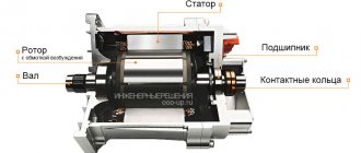
The main parts of a synchronous generator: stationary - the stator, rotating - the rotor, which is an electromagnet, and two main windings.
- One stator winding (“excitation winding”) is powered from a direct current source, the function of which is performed by an electronic voltage regulator. The regulator is used in self-excited generators. The principle of self-excitation is based on the fact that the initial excitation is carried out using the residual magnetism of the SG magnetic circuit. In this case, the alternating current energy comes from the stator winding of the SG. A complex of a step-down transformer and a semiconductor rectifier-converter transforms it into direct current energy.
- The current flowing in the stator field winding induces an emf on the generator armature field winding. The exciter stator, as a structural element, may be absent, and then its functions are performed by permanent magnets.
- The rotor winding in which the EMF is induced is called the armature field winding, or exciter armature.
- The alternating voltage arising on the armature winding of the exciter is rectified in a block of rotating diodes, which are also called the phrase “diode bridge”, and turns the power winding of the rotor into a rotating electromagnet, which induces an EMF in the power winding of the SG stator.
- Power windings and field windings are mounted in the slots of the armature and rotor.
- Based on the type of output voltage, generators are divided into single-phase and three-phase. Three-phase synchronous generators are mainly used in industry, while single-phase ones are used in everyday life.
The stator design includes a housing, inside of which there is a core, or a package assembled from sheets of electrical steel of a special shape. The quality of the electric current is influenced by such factors as: the integrity of the sheets in the package (they can be solid or composite), the quality and material of the winding. Copper enamel wire is used for winding, and in cheap devices it is possible to replace copper with aluminum.
Rotors are manufactured salient-pole or non-salient-pole.
- Salient pole rotors are designed for synchronous generators operating with internal combustion engines at low speeds of 1500 and 3000 rpm.
- Non-salient pole rotors are in demand in high-speed (more than 3000 rpm) high-power alternating electric current mechanisms. They are usually placed on the same shaft as steam turbines. Such SGs are called “turbogenerators”.
6.2. EMF OF A SYNCHRONOUS GENERATOR
As shown above, the magnitude of the EMF induced in the stator winding is quantitatively related to the number of turns of the winding and the rate of change of the magnetic flux:
Moving on to the actual values, the EMF expression can be written as:
where n is the rotation frequency of the generator rotor, Ф is the magnetic flux, c is a constant coefficient. When a load is connected, the voltage at the generator terminals changes to varying degrees. Thus, increasing the active load does not have a noticeable effect on the voltage. At the same time, inductive and capacitive loads affect the output voltage of the generator. In the first case, an increase in load demagnetizes the generator and reduces the voltage; in the second, it is biased and the voltage increases. This phenomenon is called anchor reaction. To ensure stability of the generator output voltage, it is necessary to regulate the magnetic flux. If it weakens, the car must be magnetized
, when increasing -
demagnetize
. This is done by regulating the current supplied to the excitation winding of the generator rotor.
Technical characteristics of the DC generator
To evaluate the function of synchronous generators, the same characteristics are used as those used in direct current generators. Only some conditions differ and are supplemented.
READ MORE: The best computer chairs rating of chairs for working with a computer at home Top manufacturers
The main characteristics of a synchronous generator are:
- Idling is the dependence of the EMF of the device on the excitation currents, and at the same time is an indicator of the magnetization of the magnetic circuits of the machine.
- An external characteristic is the dependence of the device voltage on the load currents. The voltage of the unit changes differently depending on the increase in load for its different types. The reasons that cause such changes are the following:
- Voltage drop across the inductive and active resistance of the device windings. It increases as the load of the device, that is, its current, increases.
- Change in the emf of the unit. Occurs depending on the reaction of the stator. With active loads, a decrease in voltage will be caused by a voltage drop in all windings, because the stator reaction entails an increase in the emf of the generator. For active-capacitive types of load, the magnetization effect causes an increase in the current voltage value compared to the nominal value.
- The regulating characteristics of a synchronous generator are the dependence of the excitation currents on the load currents. During the operation of synchronous units, it is necessary to maintain a constant voltage at their terminals, regardless of the nature and magnitude of the loads. This is easy to achieve if you regulate the EMF of the generator. This can be done by changing the excitation currents automatically depending on changes in the loads, that is, with an active-capacitive load, you need to reduce the excitation current to maintain a constant voltage, and with an active-inductive and active load, you need to increase it.
The power of a synchronous generator is determined by the following values:
- Appropriate voltage in the electrical network.
- Its EMF.
- Angle of measurement.
The operation of the generator is characterized by dependencies between the main quantities, which are called its characteristics. The main characteristics include:
- dependencies between values when idling;
- characteristics of external parameters;
- adjusting values.
We partially disclosed some adjustment characteristics and idle speed dependencies in the “Classification” section. Let us dwell briefly on the external characteristics that correspond to the operation of the generator in nominal mode. The external characteristic is very important, since it shows the dependence of voltage on load, and is taken at a stable armature speed.
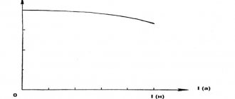
The external characteristic of a direct current generator with independent excitation is as follows: this is a curve of voltage versus load (see Fig. 5). As can be seen in the graph, a voltage drop is observed, but it does not greatly depend on the load current (while maintaining the speed of the engine rotating the armature).
READ MORE: Drip irrigation implementation from simple to complex with your own hands - at the dacha and in the greenhouse from bottles to the system
Rice. 5. External characteristics of the GPT
In generators with parallel excitation, the dependence of voltage on load is more pronounced (see Fig. 6). This is due to a drop in the excitation current in the windings. The higher the load current, the faster the voltage at the generator terminals will drop. In particular, with a gradual drop in resistance to the short-circuit level, the voltage will drop to zero. But a sudden short circuit in the circuit causes a backlash from the generator and can be fatal for an electric machine of this type.
Rice. 6. Characteristics of GST with parallel excitation
An increase in load current with series excitation leads to an increase in EMF. (see top curve in Fig. 7). However, the voltage (lower curve) lags behind the emf because some of the energy is wasted in electrical losses from the eddy currents present.
Rice. 7. External characteristics of a generator with series excitation
Please note that when it reaches its maximum, the voltage begins to drop sharply with increasing load, although the EMF curve continues to tend upward. This behavior is a disadvantage that limits the use of this type of alternator.
In generators with mixed excitation, counter-connections of both coils are provided - serial and parallel. The resulting magnetizing force with consonant switching is equal to the vector sum of the magnetizing forces of these windings, and with counter switching - the difference of these forces.
During the process of smoothly increasing the load from idle to the nominal level, the voltage at the terminals will be almost constant (curve 2 in Fig. 8). An increase in voltage is observed if the number of conductors in the series winding exceeds the number of turns corresponding to the nominal armature excitation (curve 1).
The change in voltage for the case with a smaller number of turns in a series winding is depicted by curve 3. The counter-connection of windings is illustrated by curve 4.
Rice. 8. External characteristics of GST with mixed excitation
Generators with counter-connection are used when it is necessary to limit short-circuit currents, for example, when connecting welding machines.
In normally excited mixed-type devices, the excitation current is constant and almost independent of the load.
Anchor reaction
When an external load is connected to the generator, the currents in its winding form their own magnetic field. Magnetic resistance of the stator and rotor fields appears. The resulting field is stronger at those points where the armature approaches the poles of the magnet, and weaker where it runs away from them. In other words, the armature reacts to the magnetic saturation of the steel in the coil cores. The intensity of the armature reaction depends on the saturation in the magnetic circuits. The result of this reaction is the sparking of the brushes on the commutator plates.
The armature reaction can be reduced by using compensating additional magnetic poles or by shifting the brushes from the center line of the geometric neutral.
The average value of the electromotive force is proportional to the magnetic flux, the number of active conductors in the windings and the frequency of rotation of the armature. By increasing or decreasing these parameters, you can control the magnitude of the EMF, and therefore the voltage. The easiest way is to achieve the desired result by adjusting the armature rotation speed.
Power
A distinction is made between the total and useful power of the generator. At constant EMF, the total power is proportional to the current: P = EIa. The useful power supplied to the circuit is P1 = UI.
An important characteristic of an alternator is its efficiency - the ratio of useful power to total power. Let us denote this quantity by the symbol ηe. Then: ηe=P1/P.
At idle speed ηe = 0. The maximum efficiency value is at rated loads. The efficiency of powerful generators approaches 90%.
6.3. SYNCHRONOUS MOTOR
6.3.1. DESIGN AND OPERATING PRINCIPLE
The design of a synchronous motor is the same as that of a synchronous generator. When current is supplied to the three-phase stator winding, a rotating magnetic field appears in it. Its rotation frequency is determined by the formula:
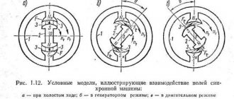
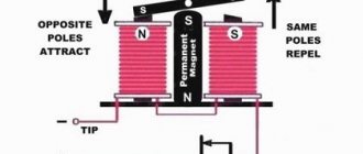
where f is the frequency of the supply network current, p is the number of pole pairs on the stator. The rotor, which is often an electromagnet, will strictly follow the rotating magnetic field, i.e. its rotation speed n2 = n1. Let's consider the principle of operation of a synchronous motor using the following conditional model (Fig. 6.3.1.). Let the stator magnetic field be modeled by a system of rotating magnetic poles N - S.
The motor rotor is also a system of electromagnets S - N, which are “engaged” with the poles on the stator. If there is no load on the motor, then the axes of the stator poles will coincide with the axes of the rotor poles ( = 0). If a mechanical load is connected to the rotor, then the axes of the stator and rotor poles may diverge by a certain angle. However, the “magnetic coupling” of the rotor to the stator will continue, and the rotor speed will be equal to the synchronous frequency of the stator (n2 = n1). At higher values, the rotor may come out of the “clutch” and the engine will stop. The main advantage of a synchronous motor over an asynchronous one is the provision of synchronous rotor speed under significant load fluctuations.
6.3.2. SYNCHRONOUS MOTOR STARTING SYSTEM
As we showed above, synchronous rotation of the rotor is ensured by the “magnetic coupling” of the rotor poles with the rotating magnetic field of the stator. At the first moment of starting the engine, the rotating magnetic field of the stator appears almost instantly. The rotor, having a significant inertial mass, will not be able to immediately come into synchronous rotation. It must be “accelerated” to subsynchronous speed by some additional device. For a long time, the role of an accelerating motor was played by an ordinary asynchronous motor, mechanically connected to a synchronous one. The rotor of a synchronous motor is driven to subsynchronous speed. Next, the engine itself is pulled into synchronism. Typically, the power of the starting motor is 5-15% of the power of a synchronous motor. This allows the synchronous motor to be started only at idle or with a low load on the shaft. The use of a starting motor with a power sufficient to start a synchronous motor under load makes such an installation cumbersome and expensive. Recently, the so-called asynchronous starting system
synchronous motors. For this purpose, rods are hammered into the pole pieces, reminiscent of the short-circuited winding of an asynchronous motor (Fig. 6.3.2.1).
During the initial start-up period, a synchronous motor operates as an asynchronous one, and subsequently as a synchronous one. For safety reasons, the excitation winding is short-circuited in the initial starting period, and in the final period it is connected to a direct current source.
Principle of operation
The stator and rotor are the main components of a synchronous generator (SG).
Operating principle of a synchronous generator
As shown in the figure, a synchronous generator most often produces power when the rotor rotates along with a magnetic field whose lines intersect the stator winding, which is stationary. The field is created from an additional exciter (additional generator, battery, etc.).
The process can occur in reverse - a rotating conductor is in a stationary magnetic field. Here the problem of current collection through the collector unit arises. For low-power alternating current generators, this circuit is quite suitable. It is usually used in mobile installations.
EMF is generated in the SG:
e = 2πBlwDn, where
B – magnetic induction;
l is the length of the stator groove;
w – number of turns in the stator winding;
D – internal diameter of the stator.
The main power industry is built on a voltage of 15-40 kV. Transferring energy through the SG collector is difficult. In addition, the moving winding is subject to shock loads and rotation at variable speeds, which creates insulation problems. Because of this, the armature windings are made motionless, since the main energy passes through them. The exciter power does not exceed 5% of the total power of the SG. This allows current to pass through the moving unit.
In AC machines of low power (several kilowatts), the rotor is made with permanent magnets (neodymium, etc.). It does not require the installation of moving contacts, but then difficulties arise with regulating the output voltage.
6.4. JET SYNCHRONOUS MOTOR
In laboratory practice, in everyday life and in low-power mechanisms, so-called synchronous reluctance motors
. They differ from ordinary classic cars only in the design of the rotor. The rotor here is not a magnet or an electromagnet, although its shape resembles a pole system. The operating principle of a synchronous reluctance motor is different from that discussed above. Here, the operation of the motor is based on the free orientation of the rotor in such a way as to provide the stator magnetic flux with better magnetic conductivity (Fig. 6.4.1).
Indeed, if at some point in time the maximum magnetic flux is in phase A - X, then the rotor will take a position along the flux FA. After 1/3 of the period, the flow in the B-U phase will be maximum. Then the rotor will turn along the PV flow. After another 1/3 of the period, the rotor will be oriented along the flow. FS. So the rotor will rotate continuously and synchronously with the rotating magnetic field of the stator. In school practice, sometimes, in the absence of special synchronous motors, the need for synchronous transmission arises. This problem can be solved using a conventional asynchronous motor by giving the rotor the following geometric shape (Fig. 6.4.2).
6.5. STEPPER MOTOR
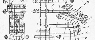
This type of motor is a direct current machine, although its operating principle is similar to a synchronous reluctance motor. As can be seen from Fig. 6.5.1, the motor stator has six pairs of projecting poles.
Every two coils located on opposite poles of the stator form a control winding connected to the DC network. The rotor is two-pole. If you connect coils of poles 1 - 1′ to a DC source, then the rotor will be located along these poles. If you use the coils of poles 2 - 2′, and de-energize the coils of poles 1 - 1′, then the rotor will turn and take a position along poles 2 - 2′. The same rotation of the rotor will occur if coils of poles 3 - 3′ are connected to the network. So, in steps, the rotor will “follow” its control winding. The advantage of stepper motors is that they have absolutely no “self-propulsion”. They rotate and are strictly fixed in steps proportional to the number of poles on the stator. This quality makes it indispensable in particularly precise mechanisms (for clock drives, nuclear fuel supply mechanisms in reactors, in CNC machines, etc.). Stepper motors are controlled using various electronic devices (Schmidt triggers, etc.).
Digital library
General technical disciplines / General energy / 2.1. Designs of synchronous generators
Virtually all industrial electrical energy in the country is generated using thermal power
(TPP),
hydraulic
(HPP) and
nuclear
(NPP)
power plants
.
In different countries, the share of electricity produced at different types of power plants is not the same. In Russia, thermal power plants currently provide approximately 69-70%, nuclear and hydraulic power plants each provide 15% of the total amount of electricity. The cost per unit of electricity generated at stations of these three types can vary dramatically. The capital costs of their construction, operating costs, level of automation, degree of reliability, dependence on the season and the characteristics of their climatic and geographical location and many other circumstances vary. There is only one thing that unites them. They are required to generate current at a standard frequency of 50 cycles per second, or 50 Hz, the required voltage level for the network to which electrical machines
operating in the mode of alternating current generators installed at each station are connected.
Absolute equality of voltage frequencies of hundreds of simultaneously operating generators can be ensured only by electrical machines of a special type - synchronous
generators operating simultaneously in the rhythm of a single time with strictly defined rotation speeds of their moving parts, called
rotors
.
It should be noted that all electric machines have the property of reversibility. Any electric generator
can operate as
an engine
, i.e. convert electrical energy into mechanical energy. Each power plant is equipped with a large number of electric motors that satisfy the station’s own needs.
Synchronous generators
(SG), designed to convert the mechanical energy of a steam, gas or hydraulic turbine that rotates the SG rotor into electrical energy, have a stationary part called
a stator
.
The moving part of the generator (rotor) can be made with a concentrated winding. In this case, the rotor and the generator itself are called salient pole. If the rotor winding is distributed, the rotor and generator are called non-salient pole.
In Fig. 2.1 schematically shows the cross section of a synchronous salient pole
machines with four poles on the rotor
2
of alternating polarity
N-SNS
.
A concentrated field winding 4
placed on the rotor is flown around by a direct current that excites
the magnetic field
of the rotor. The rotor is driven into rotation by a source of mechanical energy. Most often it is steam, gas or hydraulic
a turbine that produces mechanical torque. The turbine rotation speed can vary - from tens to hundreds and even thousands of revolutions per minute. Lower rotation speeds apply to hydraulic turbines, while higher speeds apply to other types of turbines.
Direct current to the rotating field winding 4
fed through slip rings
5
.
When the rotor rotates, the magnetic field of the field winding moves relative to the stationary stator winding 3
, placed in the grooves of the stator core
1
, which causes (induces)
electromotive force
(EMF) in the winding.
EMF frequency ( f
1) equal to the product of the rotor speed (
n2
) in revolutions per second by the number of rotor pole pairs (
p
):
f
1 =
p
n2
.
For our example (see Fig. 3.1) p
= 2, i.e.
number of poles 2 p
= 4.
Synchronous generators rotated by steam and gas turbines are called turbogenerators, and those rotated by hydraulic turbines are called hydrogenerators.
Most of the country's turbogenerators have a number of pole pairs equal to one. So, for the network 50Hz
n
2 =
f
1 /
p
= 50 s-1 or
n
2 = 60
f
1 /
p
= 3000 rpm.
For countries where the voltage frequency is 60Hz (USA, Japan, etc.), the frequency
rotor rotation is 3600 rpm. For generators with more than one number of pole pairs, the rotor speed will be the quotient of 3000 (or 3600) divided by the number of pole pairs, rpm:
1500, 1000, 750, 600, etc. (for 50Hz)
or
1800, 1200, 900, 720, etc. (for 60Hz).
Appearance of a salient pole rotor
(2
p
= 12) and its cross section are shown in Fig. 2.2.
Non-salient pole rotor
, in which the excitation winding is not concentrated, but distributed over the slots, is shown in Fig. 2.3.
Such rotors are used in turbogenerators, and the number of pole pairs is one, less often two. A salient pole synchronous machine driven by a hydraulic turbine, i.e. a hydraulic generator (Fig. 2.4), most often has a vertically oriented shaft and is “suspended” on a thrust bearing, which absorbs not only the masses of the generator and hydraulic turbine, but also the axial pressure of water on the blades of the hydraulic turbine.
A turbogenerator, rotated by a steam or gas turbine, has a horizontally located shaft (Fig. 2.5), supported by two plain bearings.
The mass of an electric machine increases with decreasing frequency of its rotation. Hydrogen generators have a rotation speed that is approximately 6-60 times lower than turbogenerators. This difference is due to the difference in the types of steam, gas and hydraulic turbines used in these machines, and also depends on the nature of the water sources used for hydroelectric power plants (water flow, slope of water flow, terrain, taking into account the economic feasibility of the exploited area). Due to the lower rotation speeds of hydraulic units, the total masses of hydraulic generators reach 1.5-2 thousand tons and are several times higher than the masses of turbogenerators of similar power. This makes it impossible to use a horizontal shaft arrangement with simpler plain bearings.
The diameters of the rotors of turbogenerators rotating at a speed of 50 s-1 do not exceed 1.1-1.25 m with a rotor length of up to 8 m. The rotors of hydrogenerators reach a diameter of 15–20 m and a length of up to 5 m.
6.6. COLLECTOR AC MOTOR
Brushless asynchronous and synchronous motors, although they have many positive qualities, have significant disadvantages. They do not allow for sufficiently smooth and economical rotation control. This gap is partially filled by AC motors. Commutator motors are single-phase and three-phase. The rotor of a single-phase commutator motor is made in the form of a cylinder with phase windings, the stator is salient-pole. Since the winding of the stator poles, connected to the alternating current network, creates a pulsating magnetic field, all elements of the magnetic circuit of the machine are assembled from separate sheets of electrical steel. Torque in a single-phase commutator motor is created by the interaction of currents in the rotor winding with the magnetic flux of the poles. In Fig. 6.6.1 - shows a diagram of connecting a commutator motor to the network.
Commutator motors can operate on either AC or DC power. This circumstance served to give them the name of universal commutator motors. Commutator motors are widely used to drive sewing machines, vacuum cleaners, etc.
AC appliance
A synchronous alternating current generator is an electric machine that converts mechanical rotational energy into electrical energy of alternating currents. Powerful generators of such currents are installed:
- hydrogenerator turbogenerator – at power plants;
- AC devices of relatively low power - in autonomous power supply systems (gas turbine power plant, diesel power plant) and in frequency converters (motor-generator).
Currently, many types of such devices are produced, but they all have a common structure of the main elements:
- armature (stator) – stationary;
- rotor rotating around an axis.
In large industrial generators, an electromagnet, which is a rotor, rotates. At the same time, the windings with induced EMF, placed in the stator slots, remain motionless.
In devices such as a low-power synchronous generator, the magnetic field is created by a rotating permanent magnet.