New power generators
> Generators > New energy generators
New energy generators - what is it about? Currently, it is still profitable to obtain energy from oil, gas and coal. Using hydroelectric power is labor-intensive and costly, and nuclear power is dangerous. Natural fuel reserves will soon come to an end; it is imperative to look for new sources of alternative and free energy. The CE designation refers to independent energy from the environment. The picture below shows Nikola Tesla's famous free energy generator in action.
Nikola Tesla Free Energy Generator
For the development of any civilization, a continuous increase in replenishable free energy is necessary; its new sources are constantly being sought. To do this, it is necessary to create self-powered generators that use the following phenomena:
static electricity; features of the action of the magnetic field created by permanent magnets (blocking generators); heat extraction by mechanical heating; use of earth and space resources; heat pumps; CE of water, wind and the earth's magnetic field; creation of biogas plants; obtaining hydrogen fuel from water; CE of the sun.
What previously seemed like science fiction is now finding industrial application, although the principle of obtaining free energy is costly. New factory-made devices have high prices and not all generators live up to expectations. Therefore, it is advisable to reduce some of the costs by making the installations yourself.
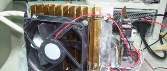
Peltier elements
Initially, the elements found application in military and space technology, which required a not very powerful device that was also subject to vibrations and shaking. Now new devices are widely used in everyday life, most often for cooling electronic equipment and in the manufacture of small portable refrigerators. Refrigerators with modules can be made with your own hands, but they are also available for sale.
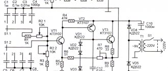
The Peltier effect occurs when a constant voltage is applied to different surfaces of a semiconductor wafer: one side heats up and the other cools. The process is reversible: when a temperature difference is maintained between the sides of the plate, an electric current flows between them and the device acts as a generator. The diagram of its structure is shown in the figure below.
Thermoelectric generator (Peltier element)
This makes it possible to use a Peltier element as an electricity generator. Powerful installations here will be too expensive, but as independent chargers when assembled with your own hands for mobile phones, they are just right.
The advantage of a thermoelectric generator is the absence of moving parts, which usually wear out and require maintenance. The disadvantage is low productivity, since while one side is working, the other side has to dissipate energy into the external environment.
Evaporation pumps
The operating principle of a heat pump is based on collecting and increasing heat potential through a reverse Carnot cycle. The system is filled with freon and consists of the following parts:
- external and internal circuits with coolant;
- compressor;
- evaporator;
- capacitor.
Thermal energy is taken from the environment. It is conditionally free, since the temperature of water, air and soil is always different
Its constant renewal is important. The operating principle of a heat generator can be simulated by installing a heat exchanger inside a regular refrigerator through which warm water is pumped
The generator will work to cool it, and the heat will be released in the radiator on the rear wall of the refrigerator. Using this method, a heat pump works to heat a house, taking heat from the environment and transferring it indoors. Sources of free thermal energy can be technical or ground water, a reservoir, outside air, or soil.
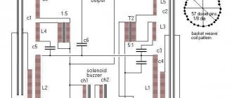
The figure below schematically shows a home heating installation using a heat pump.
Heat pump operation diagram
The heat input comes from the external circuit (blue), through which the coolant circulates with the selection of heat (free energy) from the surrounding space, for example, from a reservoir. In the evaporator, the coolant transfers heat (4-70C) to the refrigerant circulating through the heat pump, the boiling point of which is only +100C.
The refrigerant boils and turns into a gaseous state. The coolant, having given up some of the heat, is used for heating, and the gaseous refrigerant is supplied to the compressor, where it is compressed and its temperature rises significantly.
How we made the largest Tesla coil in Russia
Historical reference
The 19th century was a sort of Wild West era in the experimental physics of electromagnetism. Robert Van de Graaff, Lord Kelvin, Nikola Tesla and many other scientists, researchers and engineers discovered more and more new phenomena, and then scaled the installations that produced them to colossal sizes. Some of their creations still function today, such as the six-meter-tall giant Van de Graaff generator at the Boston Science Museum, while others, like the well-known Wardenclyffe Tower, were never born.
With the passage of time and the development of science and technology, the attention of scientists switched to other directions, but individual enthusiasts continued to collect, study and improve classical developments in the field of high voltages, electrostatics, plasma physics - some due to an undying belief in the theory of the ether and free energy, some - out of curiosity, or to solve highly specialized applied problems, someone simply because it gave him pleasure.
Recently, since about the end of the 90s, this branch of engineering problems has been experiencing a renaissance associated with the show business and entertainment industry's interest in the attention-grabbing discharges of Tesla coils, which has intensified in the last decade with the invention of DRSSTC, which currently represents the most a technically advanced type of Tesla coil, using power transistors instead of a classic spark gap, which allows you to quickly - over several periods of oscillation - change the frequency of the discharge (BPS) and, as a result, play music directly with the help of appearing lightning. One example is the well-known production model OneTesla, which, despite all the ill-conceived design proposed by the authors, is quite functional with a certain amount of hands. At the moment, Tesla transformers and related devices (Jacob ladders, Marx and Cockcroft-Walton generators, plasma columns, Van de Graaff generators, etc.) of various sizes and entertainment are used on an ongoing basis in a number of show projects organized around them in USA (Arc Attack), Russia (TeslaFX), Great Britain (Lords of Lightning), China (alas, not taught hieroglyphs) and other countries, periodically shine in show business (special effects in Harry Potter, The Sorcerer's Apprentice, Metallica concerts, etc. ), and are also present as an exhibit in every self-respecting science museum.
Size matters
In short, at one point a group of amateur engineers, long and firmly steeped in collective Tesla construction, decided that they were already bored playing in the sandbox, making small indoor (and even medium-sized outdoor) coils, and decided to do something special. At that time, we already had (as it seemed to us) enough experience in developing Tesla coils of various topologies, and the existing mathematical model allowed scaling the standard design several times. In fact, the only clearly noticeable restrictions were the dimensions of the available space, the power of the outlet, and finances (although, what can we say, in the end it all comes down to finances). Having estimated the budget, man-hours and other boring details, it was decided to limit the installation dimensions to about three meters in height, with an estimated power of about 30-40 kW. For those knowledgeable: Final technical specifications
- Technology: DRSSTC
- Total height: 3.3 meters
- Total weight: ~130 kg
- Power: 3ph 380 V
- Resonance frequency: ~50 kHz
- Dimensions of the secondary winding: 310x1800 mm, wire 1.06 mm
- Power section topology: full bridge, transistors CM600DU-24NFH
- Peak power consumption: ~35 kW
- Peak loop power: ~2 MW
- Peak loop current: 3800 A
- Primary circuit capacitance: 1.2 µF
- Inverter electrolyte capacity: 18000 uF, 900 volts
- Maximum recorded shock length: 6 meters
The technology, of course, was chosen by DRSSTC, since with the right approach and the absence of errors, its cost (as well as weight and dimensions) turns out to be significantly lower than that of other options (spark gap or radio tube) with the same final parameters. And, of course, you can play music on it.
Modular principle
When initially designing a sufficiently large Tesla coil, the project can be divided into several modules (primary winding, secondary winding, toroid, housing, power inverter, driver, control panel, auxiliary electrical equipment, etc.), each of which is designed and manufactured separately, after which they come together, are sequentially adjusted and debugged in the process, and eventually explode and begin to emit lightning. Usually, most Tesla transformers are assembled by enthusiasts alone from start to finish, but we, firstly, already had a more or less well-coordinated team with a distribution of functions (project manager, designer, developer (aka tester), and several people on hand - installer, mechanic, etc.), and, secondly, the task itself was quite ambitious, and I wanted to do it without extra costs, but at the same time more or less high quality, as far as possible for a prototype and unique design. Therefore, everyone could do their own thing, communicating in parallel to synchronize the modules with each other, and I, being this same project manager, can talk about each of the modules separately, and also show what happened in the end.
Preparation and material processing
After discussion, comprehension and various verbiage on the topic, the general concept was approved by a collective decision and I drew a primitive sketch in 3ds max. The sketch was needed to understand the scale of the task, to understand the basic relative proportions of the modules, as a starting point for the design and to raise the morale of the team. Based on the sketch, the designer assembled the project in Creo Elements (then Pro/Engineer), already observing specific dimensions, methods of connecting parts to each other, and other nuances. Based on the results of this project, drawings were created: housing parts, primary winding base, toroid, box for automation and electrical, as well as a block of primary circuit capacitors (MMC).
As construction materials, we used 18 mm thick fiberglass, processed by waterjet cutting (due to its high structural and thermal stability, other processing methods turned out to be unprofitable), thick plywood for the body and aluminum-plastic composite for the automation unit (for shielding from the powerful power generated by the coil electromagnetic interference front, which has a detrimental effect on its own control circuits), as well as polycarbonate in a number of places. The plywood and plastic were processed on a CNC router, which was owned by a neighbor in the factory, where our team dealt with all this obscenity. Creo Elements allows you to immediately create ready-made control programs for CNC, which helped a lot in the process - we simply, in fact, rented a machine and did what we needed when we needed it.
Primary and secondary
The secondary winding was wound on a classic frame - a large orange PVC sewer pipe (seriously, this is the best available option for Tesla coils of any size in terms of price, availability and suitability for the task). Enameled wire (diameter 1.06 mm) wound turn by turn in one layer, then coated with epoxy resin, turned the pipe into a huge inductor, eagerly awaiting its moment of glory - a secondary version of the giant Tesla coil. The final dimensions of the pipe were 310x1800 mm.
We wound the primary winding - also a classic - with a copper tube for air conditioners, 22 mm (7/8 inch) in diameter. The coils neatly fell into grooves cut out in fiberglass by a stream of water with an abrasive under pressure of thousands of atmospheres, and now two modules, the primary and the secondary - the skeleton of any Tesla coil - were connected to each other. The project gradually took shape and color.
Toroid
With the toroid, a necessary element of any powerful Tesla coil, however, things turned out to be more complicated. Initially, it was also planned to follow the proven path and use aluminum corrugation for ventilation. In practice, it turned out that this is an extremely one-time solution - the corrugation instantly wrinkles from any careless movements, and given the planned dimensions, it will have to be replaced every time the device is transported.
Therefore, after some research on the issue, I stole the idea and came across one interesting option on the Internet, and the designer modeled it taking into account our scale and issued a project for assembly. The fact is that the main requirement for the Tesla coil toroid is its “smoothness” from the point of view of electromagnetic fields, since any sharp points or irregularities represent points of formation of a corona discharge, which causes air breakdown before maximum power is achieved, and, in addition, , take over part of the useful length of the lightning. But there is one nuance here, related to the fact that the field lines seem to encircle the toroid with equipotential zones, as a result of which it can be assembled from component parts, which, when put together in the correct way, form a field smooth enough when the Tesla coil operates to prevent the appearance of discharge where it is not necessary.
In general, the result turned out to be very unusual in appearance, relatively simple to manufacture, reliable in operation and surprisingly effective in comparison with other known versions of this important part of the Tesla coil. The diameter of the aluminum pipe is 50 mm, and the total size of the entire resulting thing, reminiscent of a UFO, is about two meters in diameter. The spacer circles for the tubes were cut out of plywood using the same CNC router, and I welded the central frame from angle steel.
At this point, in principle, the construction part was completed.
Power section
In a power inverter for large Tesla coils, IGBT modules are often used - these are black (or white) bricks with two or three (sometimes up to 10) power terminals and several control pins, routinely used in power inverters - powerful charging units, transformer substations, frequency converters for motors, electric vehicles, etc. Due to the large size of the crystal, these modules are able to withstand significant short-term overload of operating current (up to 10 times the nominal), which is extremely beneficial in a Tesla coil pulse inverter using DRSSTC technology, since the operating cycle (the time during which oscillations occur in the circuits and current flows through the transistors, heating their crystals), it is usually about 5-10%. But, on the other hand, the vast majority of these IGBT modules are designed for operating frequencies of the order of a few, less often tens of kilohertz (however, recently the situation has been improving and modern modules can operate up to 100 kHz). Using them at higher frequencies often leads to problems with shutter control, overheating and explosions (where would there be explosions).
The cost of one module, even used, can be relatively high (from a few to hundreds of thousands of rubles), so we decided to play it safe and supply two CM600DU-24NFH modules (600 amperes continuous current, 1200 volts, two transistors) with a pulse current reserve in a half-bridge connection) according to the “full bridge” scheme (as is known, a full bridge is made from two half-bridges - K.O.), or simply “bridge”. Placed on a radiator corresponding to their dimensions through a couple of teaspoons of KPT-8 thermal paste, they were connected by copper busbars and equipped with the necessary body kit - power electrolytic and film capacitors.
There's a lot of clever empirical know-how in coming up with an actual way to connect these parts together, designed to reduce the risks and maximize the reliability of such designs, but the margins of this post are too narrow for me to talk about them, if you know what I mean. There was no guarantee that the resulting thing wouldn't explode the first time you tried to turn it on, but at the time it seemed like an acceptable risk.
Automation and electrics
The control electrics did not contain anything particularly interesting. It was necessary to ensure smooth charging of the electrolytes (so that they would not knock out the circuit breakers in the panel when the unit was turned on) - an automatic starter (essentially a large power relay) and several power resistors handled this.
A 150-amp diode bridge rectified the network (by the way, the entire structure was created, of course, for three-phase power supply, which was associated with a lot of different interesting discoveries - before we had not done anything for three phases, especially of such power), fans blew through the diode bridge and at the same time, the radiator of the power section, and the lights on the front panel represented a traffic light, kindly informing when it is possible to touch parts of the coil with your hands, when it is better not to, and when it is advisable to be at the maximum possible distance from it so as not to catch a discharge on the top of the head.
Driver
The control driver is a separate topic, and perhaps someday I will be able to talk about it in more detail. Its main purpose is to supply a control signal to the gates of transistors at the right moments, turning them on and off in such a way as to maintain and enhance the oscillations occurring in the primary circuit, while modulating them with the frequency supplied to it at the input from the control panel (this is exactly what is necessary for reproducing melodies on Tesla coils). Well, there are also a lot of different functions that optimize this process and process all exceptions (such as exceeding the maximum allowed current for transistors - OCD, overheating protection, and so on), a phase detector, the so-called. a predictor that ensures switching of transistors at zero current, and other things absolutely necessary for the operation of the Tesla coil inverter. Its actual circuit design (as well as the board layout, photographs of the board, information about the components used and the fact of the existence of this board) is the intellectual property of the developer, and therefore I will not be able to share it, but even if I could, I am afraid that I will not have enough understanding and professionalism to clearly talk about it. The Tesla coil is very easy to describe using finger analogies, but a mathematical model that is correct from the point of view of electronics development is extremely complex and contains a lot of non-obvious subtleties (the same as with the power part), so most Tesla builders simply use a set of empirical rules and ready-made solutions when building your own coils, which in our case was not applicable. There are a lot of articles on the network about the principles of operation of DRSSTC, as well as open (and closed, but available for purchase) driver projects, for example from the Chinese colleague Loneoceans - those interested can read more there.
MIDI remote
The control panel (also known as an interrapter) was a simple MIDI synthesizer with a few primitive settings that accepted MIDI files (or data from knobs) as input and output a control signal to the driver via an optical cable. With him, in principle, everything was simple and clear, because we decided not to waste time developing something that could be bought, and we just did that - we bought a ready-made one. It, of course, turned out to be a buggy semi-finished product, but it saved hundreds of man-hours in researching the midi protocol, making the board, debugging the microcontroller and catching the inevitable bugs. The main thing is that at that time he coped with his task perfectly. The remote control was purchased from an American fellow Tesla manufacturer, and at that time it was the only remote control on sale with SD card support, that is, capable of playing music without an external MIDI device or laptop. This was critical, since there were natural fears that interference from the operation of such a large coil would permanently freeze all electronics within a certain radius from it, and the freezing of some midi keyboard, the developers of which in a nightmare could not have foreseen such a level of parasitic signals, if this the keyboard controls the very Tesla coil, which interferes with it, fraught with uncontrolled positive feedback and, as a result... that's right, explosions. We didn't want explosions.
Since the remote control was sold in the form of a soldered and wired board with a scattering of remote parts, we had to develop a case for it that would contain the board itself, power supply, four encoders, four buttons, a display and numerous connectors (four optotransmitters, MIDI input, USB input, slot for SD card). Along the way, a lot of various kinds of shortcomings of the author were discovered, in particular, the absence of any kind of power control (powered by Krona? Lithium-ion? no, I didn’t hear), which had to be corrected and completed so that it could be used for its intended purpose. The resulting chimera, despite a number of disgusting glitches under some unfortunate conditions, successfully copes with its main task to this day. Somehow I couldn’t find a photo of it, but you can see it in one of the frames below, in the “initial check” paragraph - a black box next to the power cable on the right side of the picture. There is also a still from the video from the author of the circuit and firmware - here it is.
Capacitor battery
As a resonant capacitor, we chose power film capacitors from one of the domestic manufacturers, specially developed (according to the manufacturer’s catalog) for pulsed operating modes. Five pieces with a total capacity of about 1.2 microfarads, and a maximum voltage of 20 kilovolts, connected by a copper busbar with brass screws. By the way, a significant amount of brass fasteners was used for the entire project - due to the huge currents in kiloamperes, combined with a powerful magnetic field from the primary winding, both galvanized steel and stainless steel fasteners instantly heat up red hot, which can ultimately lead to unplanned special effects (yes -yes, explosions). Therefore, in the busbar of the capacitors, and in general in all power connections in the primary circuit, only copper and brass had to be used. The very first tests showed the naivety of trying to put something ferromagnetic and/or that does not pass electric current well enough.
Initial check
The next step was setting up the driver. To do this, it is enough to assemble the primary circuit into one whole (capacitor bank, primary and bridge), connect the driver to the bridge transistors and smoothly start applying voltage, monitoring the signal shapes in different parts of the circuit on an oscilloscope. If everything is done correctly, then self-generation occurs in the primary circuit at the design frequency (in our case, about 50 kHz). In this case, a secondary is not needed, and no discharges occur, but the collected data is enough to set up the predictor, OCD and notice errors in installation or selected parameters of parts. This part turned out to be simple and easy (by the way, in this mode, the primary winding can easily work as an induction cooker for cooking - there are precedents for frying fried eggs in a frying pan standing on top of the primary), and we went with the almost born brainchild to one large and half-abandoned workshop factory to finally test our creation in vivo.
The test turned out to be quick, bright and a little predictable: having produced several four-meter discharges, the Tesla coil said “I’m tired of you, I’m leaving” and stopped working with a loud bang somewhere inside the case. A subsequent study of this phenomenon showed that in the process of selecting the optimal frequency, we made a mistake by one turn of the primary winding, and the mismatch that arose when switching transistors was enough for them, as they say in professional Tesla-building argot, to rape, that is, to become completely unusable due to the transition the silicon they contain into a gaseous state (as in the joke that transistors operate on magic smoke - when it comes out, they stop working). A spare set of transistors remained in the laboratory, and for the rest of the allotted time we sluggishly quarreled with each other and launched other Tesla coils we had taken with us as part of a rehearsal for the GEEK PICNIC festival (which coincided with the release of the project).
What was all this for?
Well, then there was a little work on the mistakes, hectic preparations, arrival on Elagin Island, where the aforementioned GEEK PICNIC traditionally takes place in St. Petersburg, night tests before the festival day of our coil, already with a new tubular toroid and to the fullest (forgive the intentional tautology). The next day there was hour X (during which for about fifteen minutes we jumped in a crowd around the masterpiece that did not want to start, until we discovered a jamb in the editing - the current transformer was connected in the wrong phasing), Vivaldi, the Imperial March and Mario on lightning, filming it all quadcopters with cameras, half a thousand spectators looking at what was happening, some with admiration, some with surprise, some with indifference and incomprehension, some through the screens of their smartphones and tablets, several encore launches in daylight, where the discharge was barely noticeable (but it was perfectly audible ) and - after the end of the festival, but before the closing of the park - a few minutes of operation of the largest musical Tesla coil in Russia in the summer twilight, which still sometimes appears before my eyes.
Holding the remote control for such a thing in your hands and looking at almost real six-meter lightning, cutting through the air in threatening tentacles, appearing and changing with the movement of your fingers - this is still one of my most powerful memories in nine years of working on Tesla coils and high voltage special effects. But, alas, nothing lasts forever, and indignant at what was happening (they say, people don’t want to leave while you’re having fun here), the park security guard demanded that you close up the bench and roll out, which is what you had to do.
Unfortunately, since then we have never been able to fire this Tesla coil again. We have reworked the design of the power section, upgraded the driver, and have made significant progress in understanding the principles of operation of this whole thing, but the lack of a site suitable for conducting such experiments, alas, is still a difficult and expensive obstacle. The coil lies in the form of component parts at my house and is waiting in the wings. Someday I'll turn it on again. Or maybe not hers, but a new one, two or three times more. Who knows.
Launch video:
Newfag disclaimer
This is my first post on Giktimes. In case of positive criticism, I plan to talk about a number of other interesting projects on related topics in the future. If you notice in the text or design a violation of any public or unspoken rules or recommendations of the Giktimes community, please point them out to me for correction and consideration in the future.
Free energy generator: diagrams, instructions, description
Description of the electrical circuit diagram with an example
The ideas of Nikola Tesla are still alive, and many people are trying, using these ideas, to make our world a little better. Bedini's invention, called the Bedini generator, is based on Tesla's principles and John's own developments in the field of electromagnetism. This is not the first such generator; back in the year, Jim Watson showed a similar mechanism at a conference, but, as often happens with real inventors in the field of alternative energy, after that he disappeared, along with his family and all the drawings. Bedini's project was more fortunate. Bedini SchoolGirl - this name is connected with one interesting point.
Let's try to figure out what it is, by whom, for whom and why it was invented?
Adams generator
Bipolar transistors full description
Such a device can rightfully be called working, but sellers significantly exaggerate its capabilities. At one time, a patent was even received for its production in 1967, but that’s where its story should have ended. However, scammers decided to take advantage of the ignorance of many people and sell the so-called dummy for serious money.
Watch this video, they show how the device works. I would like to note that even for the show it was not possible to show its effectiveness; we only heard incomprehensible promises that many people believed.
Now let’s see why you shouldn’t buy such an Adams fuel-free generator. The maximum efficiency of its work in laboratory conditions was only 15%. This figure is not enough to even provide the minimum amount of electricity to a small room. In real conditions, the efficiency was only 3-7%. In general, the idea is not bad, even the Adams generator circuit turned out to be quite well thought out, but not yet working.
Adams oscillator circuit
Generator circuit
Controller z 5r: instructions, connection diagram
The minimum power from any device can be obtained in several ways:
- Atmospheric condensate as a source. It can be used to create a transgenerator.
- Ferrimagnetic alloys.
- Warm water.
- Through magnets. They require minimal conditions.
But you need to learn how to control this phenomenon in order for the effect to be maximum.
Free energy diagram
Magnetic generator
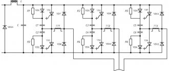
The application of a magnetic field to an electric coil is the main effect that can be achieved by using such a device. The list of main components is as follows:
- Support coil to regulate electricity.
- Feed coil.
- Locking coil.
- Starting coil, also necessary for fuel-free appliances.
The circuit includes a control transistor along with a capacitor, diodes, a limiting resistor and a load.
Creating an alternating magnetic flux is the issue in which device owners have the most questions. It is recommended to mount two circuits that have permanent magnets. Then the lines of force are organized in the opposite direction.
Self-powered
It is necessary to create a circuit that supplies the main flow of electricity to the working device. After this, the generators switch to self-oscillating mode. They no longer need external power.
This device was called “kachera”. But the correct name is blocking generator. It creates a powerful electrical impulse.
In total, there are three main groups of blocking generators:
- On field-effect transistors whose gate is insulated.
- With a base in the form of bipolar transistors.
- With vacuum tubes, such designs are also common.
Energy from the ether
Tesla Generators
The design involves the use of a transformer, like high-voltage analogues. The principle of operation is approximately the same as that of conventional products. At the output of this device, so-called excess energy is formed. They significantly exceed what was spent when launching the device. The main thing is to choose the right method for manufacturing a transformer and configure the device to work.
A brilliant seer and a guest from the future
The most famous and most mysterious enthusiast of the idea was the Serbian Nikola Tesla. The free energy generator is just one of the inventions of the brilliant scientist, the owner of almost a thousand patents. He was born in the mid-19th century in what is now Croatia. He, like some other atypical people, has two biographies.
great scientist
It is believed that the Serbian scientist not only laid the foundation for modern electrical engineering, but also made a major contribution to the continuation of the industrial revolution - its so-called second stage. Tesla gained fame in various fields of science. He is responsible for alternating current devices, a synchronous generator, an asynchronous motor and many other inventions. The official data from his biography are widely known:
- Since 1884, Nikola Tesla lived in the USA. In a short time of collaboration with Edison, he was able to improve many of his direct current devices on a dare. Later, the scientists parted ways, and the famous “War of Currents” broke out.
- In 1887, the Serb created the Tesla Electric Company.
- He studied high-frequency magnetic fields. Some of his developments are still used in medicine and electrotherapy. It is significant that the scientist first tested the effect of alternating currents on himself.
- He developed field theory and methods for transmitting electricity using multiphase alternating current. They are now the backbone of the global energy system. For example, light enters homes and businesses.
- Even before Marconi, he described the principles of radio communication. Later he improved the transmission of radio frequencies over long distances.
- Invented devices for detecting submarines and suppressing sound.
- At his instigation, outdoor advertising based on luminous tubes appeared on city streets.
- Made the first electric motor. Conducted successful tests of an electric vehicle. Invented an electric submarine.
- Worked on the study and use of x-rays.
- He predicted the appearance of weapons such as the atomic bomb, and thought through ways to study the nucleus.
- He was the first to build a device that could be controlled remotely.
- He repeatedly voiced ideas that were later used in the development of robotics.
You might be interested in The concept of grounding and ground loop
The scientist's ideas were ahead of their time. The practical use of some of his inventions is still prohibited, although they are officially patented. Modern scientists cannot repeat a number of Serbian experiments.
Mysterious wizard
Many of the scientist’s inventions went with him. Successful experiments with the ether have not yet been explained, although the principle of operation of the Tesla generator is known. Free energy from the ether was not his goal in itself. The scientist sought to understand the world. Revolutionaries in this field are always surrounded by secrets . To understand the riddle of the great Serb, it will be interesting to know:
- The future engineer and inventor could become a priest. He received not only a technical, but also a philosophical education.
- In his youth, he was fond of playing cards until he lost completely and had to pay off his debts to his relatives.
- In the USA, after a quarrel with Edison, he was a tramp, an auxiliary worker, hired out as a day laborer, and dug ditches.
- Never married. Didn't get close to anyone. Preferred to work alone.
- Penetrated the secret of ball lightning and knew how to create them artificially.
- He was superstitious and had the gift of foresight. Several times, using this ability, he saved people from possible troubles and even death.
- He had incredible performance. I slept 2 hours a day.
- He began to build a secluded laboratory on the then deserted Long Island. Officially, a tower for a radio station was supposed to appear in this place. Unofficially, it was here that ideas for using atmospheric electricity could be worked out in practice. There was allegedly not enough money to complete the project. The base was subsequently destroyed.
- The tower on Long Island is associated with rumors of the development of death rays, a directed combat emitter and an ultrasonic gun. Later, the Serb's ideas could be used to create a laser.
- During the First World War, Tesla not only raised funds to help Serbia, but also thought about creating an absolute weapon capable of destroying enemy armies at once. It is unknown how far he went along this path.
- Some researchers associate the mystery of the Tunguska meteorite with the scientist. He was really interested shortly before the fall of the celestial body in the remote and most uninhabited territories of Siberia.
- Events similar to the Tunguska events were also observed in the Indian Ocean. The Serb was accused of “shaking” the airwaves here.
You may be interested in this: Connecting a pass-through light switch according to the diagram
Tesla died in 1943. His body was found in the hotel only 2 days later. According to one version, all documents found in the room were confiscated and classified by US intelligence services. According to another, most of the genius’s papers were stolen by German or Russian intelligence.
What are they?
There are quite a lot of generator models on the market; they differ in type of design and principle of operation. By analyzing this information, you can choose the most effective and suitable option for your home. In general, generators can be divided into three main types:
- pendulum;
- magnetic;
- mercury.
The Vega generator runs on magnets and was invented by two scientists - Adams and Bedini. The magnetic rotor has the same pole orientation; rotation creates a synchronous magnetic field. The EMF stator has several windings and is supported by short magnetic pulses.
“Vega” is a working abbreviation for vertical Adams generator; it is suitable for private houses and small buildings; even for a motor boat you can assemble an engine based on this design. Short-term pulses generate the required voltage level, stimulating battery recharging during operation. Depending on the power of the selected components, the scope of use of this generator can expand.
Tesla is a famous physicist, the design of his generator is the simplest. It includes the following components.
- A capacitor to successfully accumulate and store electrical charge.
- Grounding for contact with ground.
- Receiver. Only conductive materials are used for it; the base must be dielectric. Isolation at the final stage is mandatory.
The receiver receives electricity; due to the presence of a capacitor in the design, the charge accumulates on the plates. With its help, you can connect any device to the generator and charge it.
Rossi uses cold fusion for a fuel-free generator. Although the design does not contain turbines, fuel replacement is carried out through a series of chemical reactions of nickel and hydrogen. Thermal energy is released in the chamber as the reaction proceeds.
The use of a catalyst and a small electric battery is mandatory. All costs, according to laboratory studies, are recouped more than 5 times. This model is most suitable for generating energy in residential areas. But sometimes experts argue whether it can be called completely fuel-free, since the design provides for the use of nickel and hydrogen - active chemical reagents.
For the Hendershot generator you will need:
- resonant electric coils from 2 to 4 pieces;
- metal core;
- several transformers generating direct current;
- several capacitors;
- set of magnets.
When assembling, be sure to observe the spatial orientation of the coils. The correct north-south direction will reliably generate a magnetic field in the winding. Using a Tesla coil, two or more capacitors, a battery and an inverter, a more powerful design can be made.
Khmelevsky's generator is actively used by geologists on expeditions where there is no constant source of electricity. The design includes a transformer with several windings, resistors, capacitors and a thyristor. The windings used are strictly split. The counter generation of energy by a transformer always has a positive value, which guarantees a high-quality result using resonance and voltage frequency while maintaining the amplitude for operation.
A fuel-free generator based on the interaction of a magnetic field between rollers and a metal core was invented by John Serla. The rollers move an equal distance during operation and rotate around the core; coils are installed along the diameter to generate energy. The work is started using supplying electromagnetic pulses. The alternating magnetic field gradually increases the speed of the rollers; the higher the level of rotation, the more electricity is generated. Upon reaching a certain level, you can even achieve anti-gravity: the device is slightly raised above the table surface.
The Schauberger device is a mechanical model; energy is generated by rotating a turbine and moving water or other liquid through pipes. A simple and effective law, thanks to which mechanical energy is easily converted through the through movement of liquid from bottom to top. This is possible due to cavities in the liquid and a state that is very close to vacuum.
alternative energy
Supporters of traditional physics and energy deny the possibility of creating a workable generator, using existing concepts, laws and definitions. A lot of evidence is given that such devices cannot exist in practice, since they contradict the law of conservation of energy.
Proponents of the “conspiracy theory” are convinced that calculations of the generator exist, as well as its working prototypes, but they are not presented to science and the general public, since they are not profitable for modern energy companies and can cause an economic crisis.
Enthusiasts have repeatedly attempted to create a generator; they have built many prototypes, but for some reason reports on the work regularly disappear or disappear. It has been noted that network resources dedicated to alternative energy are periodically closed.
This may indicate that the design is actually functional, and it is possible to create a generator with your own hands even at home.
Features of generator development
Tesla's practical experiments show that electricity can be generated using a generator, two coils and one additional coil without a primary coil, two windings. If you move a working and empty coil side by side at a distance of half a meter, and then simply move it away, the corona will die out. In this case, the current that is energized will not change its value depending on the position in space of the one that is not charging from the network. The explanation for the emergence and maintenance of such energy in an empty secondary winding is easily explained.
When electrical engineering developed, stations were built using alternating current. These buildings were low-power, covering one network of enterprises that were equipped with different equipment. Despite this, situations arose in which generators ran idle due to voltage surges. The steam forced the turbines to rotate, the engines worked faster, the load on the current decreased, and as a result, the automation cut off the pressure supply. As a result, the load disappeared, enterprises stopped functioning due to the surge in current, and they had to be turned off. During the development process, the situation was stabilized by connecting a parallel network.
Developed by Parker Kinetic Designs Corporation
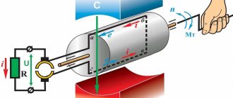
Similar even larger devices are designed and manufactured by Parker Kinetic Designs (formerly OIME Research & Development) of Austin. They produced devices for a variety of purposes, from powering railroad guns to linear motors (for space launches) and various weapon designs. 10 MJ industrial designs have been introduced for a variety of roles including electric welding.
These devices consisted of a conductive flywheel, one of which rotated in a magnetic field with one electrical contact near the axis and the other near the periphery. They have been used to generate very high currents at low voltages in areas such as welding, electrolysis, and rail gun research. In pulsed energy applications, rotor angular momentum is used to store energy over a long period and then release it in a short time.
Unlike other types of unipolar commutator generators, the output voltage never changes polarity. Charge separation is the result of the Lorentz force acting on free charges in the disk. The motion is azimuthal and the field is axial, so the electromotive force is radial.
Electrical contacts are usually made through a "brush" or slip ring, which results in large losses at the low voltages generated. Some of these losses can be reduced by using mercury or another easily liquefied metal or alloy (gallium, NaK) as a "brush" to provide virtually continuous electrical contact.
Application
In everyday life and in production, such generators are widely used in various fields and areas, but they are most in demand to perform the following functions:
- Used as motors for wind farms, this is one of the most popular functions. Many people make their own asynchronous generators to use them for these purposes.
- Operation as a hydroelectric power station with small output.
- Providing power and electricity to a city apartment, private country house or individual household equipment.
- Performing the basic functions of a welding generator.
- Uninterrupted supply of alternating current to individual consumers.
Free energy generator: diagram and description
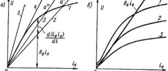
The essence is that humanity is surrounded by air, water, vibrations. So, there are two windings in the coil: primary and secondary, which are subject to vibrations, which in the process are crossed by etheric vortices in the direction of the cross section. The result induces voltage, essentially air ionization occurs. It appears at the tip of the winding, producing discharges.
An oscillogram of current fluctuations compares the curves. The inductive coupling is strong due to the transformer iron, which causes dense interweaving and oscillations between the windings. When extracted, the situation will change. The pulse will die out, but the power will expand, passing the zero point, and will break off when it reaches the maximum voltage, although the connection is weak and there is no current in the primary winding. Tesla argued that such vibrations continue thanks to the ether. The existing environment is designed to produce electricity. In practice, the working circuit of a free energy generator consists of a coil and windings. Moreover, the simplest way to obtain current looks like this (photo below):
Tesla transformer design
An apparatus for producing currents of high frequency and high potential was patented by Tesla in 1896. The device looks incredibly simple and consists of:
- a primary coil made of wire with a cross-section of at least 6 mm², about 5-7 turns;
- a secondary coil wound on a dielectric is a wire with a diameter of up to 0.3 mm, 700-1000 turns;
- arrester;
- capacitor;
- spark glow emitter.
The main difference between the Tesla transformer and all other devices is that it does not use ferroalloys as a core, and the power of the device, regardless of the power of the power source, is limited only by the electrical strength of air. The essence and principle of operation of the device is to create an oscillatory circuit, which can be implemented by several methods:
- Frequency oscillation generator built on the basis of a spark gap.
- Tube oscillation generator.
- On transistors.
- Double resonance generators are the most powerful devices.
We will assemble a device for obtaining ether energy in the simplest way - using semiconductor transistors. To do this, we will need to stock up on a simple set of materials and tools:
- copper wire with a thickness of 0.40-0.45 mm;
- A 9-centimeter plastic pipe, about half a meter long;
- 11 cm plastic pipe, 3-5 cm long;
- thick, millimeter copper wire with good insulation, 7-10 turns;
- transistor D13007;
- radiator for transistor;
- 50 kOhm variable;
- constant resistor 0.25 W and 75 Ohm.
Circuit and design of the Tesla generator
The essence of the operation of a generator device lies in the external processes that surround a person - the influence of wind, water and vibrations. The design of a simple electric current generator includes a coil in which two windings are located. The secondary element operates under vibration conditions, causing the etheric vortices to cross towards the cross section in the process. As a result, voltage is generated in the system, which leads to air ionization. This occurs at the tip of the winding, which contributes to the formation of discharges.
An oscillogram of electrical fluctuations compares the curves. The use of transformer metal in the design provides increased inductive coupling. This contributes to the appearance of a dense weave, as well as vibrations between the winding elements.
A simple drawing of a Tesla electric generator
As a result of extraction, the situation changes in the opposite direction. The signal in the system attenuates, but the operating power parameter that can be received increases beyond the zero point. After this, when the power reaches its maximum, it will break despite the weak connection and the absence of current in the primary winding. According to Tesla, these vibrations can be obtained from the ether. In such an environment, electricity generation is possible.
Fuel-free devices operate on power generated directly by the equipment. To start the devices you will need one impulse from the battery. But this invention of Tesla has not yet found application in everyday life.
The functioning of a fuel-free electric generator depends on its design features.
The design includes:
- Two metal plates. One element rises up, and the second is mounted into the ground.
- Capacitor device. Two electrical circuits are connected to this component, which go from ground and from above.
A constant discharge is applied to the metal plate, resulting in the release of special particles. The Earth's surface itself is a reservoir of minus particles, so one of the plates must be installed in the ground. The installation operates under conditions of increased charge, which leads to the flow of current into the capacitor device. The latter is powered by this current.
The “Simply About Complex” channel talked about and clearly demonstrated the principle of operation of the Tesla generator.
Characteristics of the Tesla generator
A decade after receiving the alternating current patent, Tesla created a self-powered free energy generator circuit. The fuel-free model consumes the power of the installation itself. To start it, a single impulse from the battery is required. However, this invention is still not used on the farm. The operation of the device directly depends on the design that includes the components:
- Two special iron plates, one rises up and the other is installed in the ground.
- Two wires are connected to the capacitor, coming from ground and from above.
A constant electric charge is transferred to the metal plate due to the fact that the sources emit radiant particles of microscopic size. The earth is a reservoir of negative particles, so the device terminal is connected to it. The charge is high, so the capacitor is constantly supplied with current, and thanks to this it is powered.
Neutral wire method
Voltage is supplied to a residential building using two conductors: one of them is phase, the second is zero. If the house is equipped with a high-quality grounding circuit, during periods of intense electricity consumption, part of the current flows through the grounding into the ground. By connecting a 12 V light bulb to the neutral wire and ground, you will make it glow, since the voltage between the zero and ground contacts can reach 15 V. And this current is not recorded by the electric meter.
The circuit, assembled according to the principle of zero - energy consumer - earth, is quite working. If desired, a transformer can be used to equalize voltage fluctuations. The disadvantage is the instability of the appearance of electricity between zero and ground - this requires the house to consume a lot of electricity.
Despite the fact that such a system uses the earth to operate, it cannot be classified as a source of earthly electricity. How to extract energy using the electromagnetic potential of the planet remains open.
Sources
- https://texnotoys.ru/elektronika/svobodnaya-energiya-svoimi-rukami.html
- https://FB.ru/article/220152/generator-svobodnoy-energii-svoimi-rukami-shema
- https://www.syl.ru/article/190368/new_generator-svobodnoy-energii-s-samozapitkoy-svoimi-rukami-shema-generatora-svobodnoy-energii
- https://generatorexperts.ru/alternativnye-istochniki/adamsa-vega.html
- https://FB.ru/article/339048/generator-svobodnoy-energii-shema-prakticheskaya-opisanie
- https://rusenergetics.ru/oborudovanie/generator-tesla
- https://amperof.ru/elektropribory/generator-s-samozapitkoj.html
- https://birukov.biz/index.php?cat_id=67
- https://rusenergetics.ru/ustroistvo/generatory-na-magnitax
- https://StroyVopros.net/elektrika/domashnyaya-elektrotehnika/akkumulyatoryi-bloki-pitaniya-i-batarei/bestoplivnyiy-generator.html
- https://hockey-samara.ru/elektronika/svobodnaya-energiya-svoimi-rukami.html
What do fuel-free generator manufacturers promise?
On the Internet you can find various sites that offer to buy BTG, and for quite a lot of money (on average - 12 thousand rubles). Moreover, each seller explains the principle of operation of the mechanism in his own way.
Some say that a fuel-free generator operates on some kind of “earth energy”, for others the source is ether, and others talk about static energy, which does not obey the known laws of physics, but is quite real.
IMPORTANT! The theory of the ether was relevant until the beginning of the twentieth century, until in 1910 Einstein refuted it in his scientific article “The Principle of Relativity and Its Consequences in Modern Physics.” In fact, BTG is a beautiful invention, and similar devices do not exist in nature
In fact, BTG is a beautiful invention, and similar devices do not exist in nature.
However, for those who are new to physics, the explanations about the ether and “earth energy” are quite enough to buy an expensive but useless generator.
Is it possible to make a fuel-free generator with your own hands?
If you are still in doubt, try assembling such a generator yourself. There are many different schemes on the Internet for collecting BTG at home. Among them, there were two fairly simple methods: wet (or oil) and dry.
Oil method of collecting BTG
You will need:
- AC transformer – necessary to create constant current signals;
- Charger – ensures uninterrupted operation of the assembled device;
- Battery (or regular battery) – helps accumulate and conserve energy;
- Power amplifier – will increase the current supply;
What is a lithium ion battery - device and types
The transformer must be connected first to the battery and then to the power amplifier. Now a charger is connected to this design, and the portable BTG is ready!
Dry method
You will need:
- Transformer;
- Generator prototype;
- Undamped conductors;
- Dynatron;
- Welding.
Connect the transformer to the generator prototype using undamped conductors. Use welding for this. A dynatron is needed to control the operation of the finished device. Such a generator should work for about 3 years.
The success and effectiveness of these designs largely depends on your luck. You will also need it to find all the necessary elements specified in the instructions. But you probably already guessed that all this is unlikely to work.
Adams generator
In 1967, a patent was received for the production of this generator. The BTG turned out to be working, but the power it produced was so small that it would hardly be possible to provide energy to even a small room with its help.
But scammers don't care. Therefore, on the Internet you can find sites selling the Adams generator. But why spend money on a device that won’t help you save money?
"generator n. Tesla"
"GENERAL CONCEPT"
FANTASIES ON THE THEME “FREE ENERGY”
Engines consuming hydrocarbon raw materials (gas, gasoline, fuel oil, etc.) will be expelled from industry.
Trains and forklifts will use free energy.
Aviators will be able to fly around the globe without landing for refueling.
The maximum speed of ocean-going ships will be increased from 23 to more than 100 knots, by saving space and tonnage currently used for giant boilers and coal bunkers.
Manila will be closer to Kyiv than Moscow is now. Traveling from London to Boston will take 30 hours. Asian fruits will reach New York fresher than California fruits now.
Aluminum, cheaper and more accessible due to free electricity, will replace wood and steel in the production of ships, buildings, cars and furniture. The world will be rewarded by preserving forests and the giant fires will end.
The cost of driving force in transportation, travel and communications will be reduced to a minimum.
The modern agricultural system will be significantly changed. Each farmer will have the amount of energy he needs. It will be possible to reach underground streams, and water will be available always and in all regions. Millions of arid and desert hectares will be transformed into productive fields.
Nitrogen for fertilizers will be extracted electrically from the air.
The length of the working day will be reduced, and the level of industry and production will be increased.
Imagine a car, without gasoline or other fuel, without batteries or a generator, joining heavy traffic on the streets of Kyiv, Moscow or another city.
Imagine, at an altitude of 300, 1500, 3500 kilometers above the earth, an airplane is hovering. Without a single drop of gasoline or oil on board, without batteries, without a generator, without even an engine, it tilts, descends, and flies away.
Imagine in your small cottage or apartment, or large house, the light bulbs are burning evenly. Imagine your wife in the kitchen, she is preparing dinner. Imagine watching her turn the dial on the oven and set the potatoes to bake. And at the same time, you know that the power wires going to the cottage, apartment, or house are cut off at the meter.
Imagine: at the end of each month you do not receive bills for electricity and gas.
Imagine that a car, an airplane, light bulbs and an oven move, burn and heat up under the influence of electricity from a small square wooden box measuring 35 centimeters in size and weighing less than forty kilograms.
Is it useless to imagine all this? Are you a skeptic, and remember how in the past the whole country was worried about sensational statements about a method of producing fuel from ash and gasoline from water, and nothing came of it? You have the right to be a skeptic.
But in the early 30s of the last century there was such a Harry E. Perrigo, living in the house 3000 on Michigan Avenue, Kansas City, he lived by inventing and improving his little car. The operating principles of which are similar to the structures designed by N. Tesla.