The 12 Volt voltage is used to power a large number of electrical appliances: receivers and radios, amplifiers, laptops, screwdrivers, LED strips, etc. They often run on batteries or power supplies, but when one or the other fails, the user is faced with the question: “How to get 12 Volts AC”? We will talk about this further, providing an overview of the most rational methods.
Some definitions and theory
Let's start by figuring out what definitions we will have to face.
Alternating current flows in the electrical network. Its value varies according to a sinusoidal law, it is also called “sinusoidal voltage” or simply “sinusoid”. This voltage (current) changes smoothly from zero to the amplitude value, then back to zero and again to the amplitude value, but with the opposite sign. In one period of a sinusoid there are two half-waves - “forward” and “reverse” or “upper” and “lower”.
According to the encyclopedic definition, direct current is the directed movement of charged particles whose speed and direction do not change.
This is a type of unidirectional current.
But in practice, the current is often not constant, but changes during the operation of the consumer (load), and there is also pulsation at the output of rectifiers, and galvanic elements have drawdowns under load. It turns out that “direct current” itself, as stated in the “definition,” is not used everywhere. When people say "DC power supply" they often mean constant voltage.
A few more concepts need to be highlighted here:
1. Unidirectional current - flows in one direction and can be arbitrary in magnitude.
2. Rectified voltage (or current) is constant in sign, but can vary in magnitude. If filters are not used, the alternating voltage that was rectified pulsates at twice the frequency. So at the output of the mains voltage rectifier the ripple frequency will be 50×2=100 Hz.
3. Stabilized voltage (or current) - constant in sign and magnitude.
In English-language technology and literature, alternating current is designated as AC (alternative current), and direct current is referred to as DC (direct current).
Alternating current and its properties
Alternating current cyclically changes direction and strength, characterized by the following parameters:
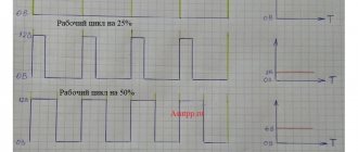
- frequency . The number of cycles (periods) per second. For example, the frequency of the current in the network is 50 Hz;
- amplitude . Maximum deviation of voltage and current from zero. Thus, the mains voltage changes from -311 V to 311 V 50 times per second;
- actual value . This is the voltage or strength of an equivalent direct current, that is, one that causes the same heat generation in the conductor as a given alternating current. The effective value is used to simplify calculations: working with constantly changing values is extremely inconvenient. For example, if you write in the formula the actual value of the alternating mains voltage, varying from -311 V to 311 V according to a sinusoidal law, you will get an equation with trigonometric functions or complex numbers. It is much easier to operate with a constant effective value of 220 V;
- form . The mains current produced by mechanical generators has a sinusoidal shape. At the inverter output it can be acute-angled, stepped, etc.
Alternating current is inferior to direct current in the following ways:
- it is of lower quality. Thus, the weld is stronger and more reliable if welding was carried out with direct current. The electronics also work better;
- at a frequency of 50 Hz it is more dangerous. It causes disturbances in the body already at a force of 50 mA, while constant - at a force of 300 mA. However, as the frequency increases, alternating current becomes less dangerous. Thus, the outstanding inventor Nikola Tesla, in public experiments, passed a high-voltage alternating current through himself (a lamp clutched in his hand glowed), having previously raised its frequency to several megahertz;
- The resistance of conductors to alternating current is higher than to direct current. An explanation of this will be given below.
But alternating current also has a useful feature: the magnetic field it creates is also variable, which means it can induce EMF (the law of electromagnetic induction) in conductors.
Alternating current makes it possible to operate the following devices:
- transformers. By increasing the voltage, losses in power lines are significantly reduced;
- induction heaters;
- throttle filters. Choke - coil. The alternating magnetic field it creates counteracts the alternating current, that is, the inductor acts as a resistance. The frequency of the current that it most strongly opposes depends on the inductance of the coil. This feature allows the choke to suppress high-frequency interference in the network.
The presence of an alternating magnetic field also explains the above-mentioned increase in conductor resistance. In it, the field also induces an emf that counteracts this alternating current. This EMF is higher in the center of the conductor, where the field lines are concentrated, and accordingly, charge carriers are forced out (surface or skin effect).
As a result, instead of the entire cross-section of the conductor, only a certain part of it passes current, which is why the resistance increases. Another difference between alternating current and direct current is the ability to flow through a circuit with a capacitor connected in series. For direct current, the gap between the plates is insurmountable, while alternating current flows almost freely, charging plates with one or the other sign.
Semiconductor Diodes and Rectifiers
Modern electronic devices use semiconductor diodes for rectification.
A diode in the broadest sense is any device that has two terminals. However, more specifically, a semiconductor diode is a device in which only one pn junction is formed.
The main feature of semiconductor diodes is that they conduct current in one direction, and if a reverse voltage is applied (the so-called “reverse bias”), then the current is not conducted until thermal or electrical breakdown of the pn junction occurs with subsequent failure of the element (with the exception of zener diodes, for example). There are many types of diodes: rectifier, pulse, detector, limiter and others, but today we are interested in rectifier diodes.
Diodes are also called “semiconductor uncontrolled valve”; they are uncontrolled because you cannot give a command for electric current to start or stop flowing.
So, a rectifier diode is a device that passes current in one direction. This phenomenon is used to convert alternating current to direct current, as well as to isolate DC circuits, for example, when it is necessary to supply several signals, independent of each other, from different sources.
In the diagram, the diode is indicated by an arrow, the direction of which indicates where the current will flow. In older diagrams, the designation of an arrow in a circle is more common.
Methods for generating electricity
Electric current is produced using the following devices:
. They consist of two parts: a stationary stator and a rotor rotating inside it. The stator is a permanent or electric magnet, the rotor contains a winding of wire. When the rotor rotates, the magnetic flux crossing its winding changes all the time, which leads, according to the law of electromagnetic induction, to the appearance of an emf. The rotor is driven by an external force: engine (car), water flow (hydroelectric power plant), steam pressure (nuclear and thermal power plants), wind, etc. The current at the generator output will be variable. To obtain a permanent one, an additional mechanical device is required - a collector;
mechanical generators- galvanic cells (GE) and batteries . Convert chemical energy into electricity through a redox reaction. The simplest GE: copper and zinc plates, immersed, respectively, in solutions of copper sulfate and zinc sulfate, isolated from each other by a porous partition (Jacobi-Daniel element). As a result of oxidation, each zinc atom on the zinc plate (anode) gives up 2 electrons, which pass through the electrical circuit to the copper plate (cathode) and reduce positively charged copper ions on it. GEs are called primary chemical current sources (CHS). Batteries are secondary HIT. The principle of operation is similar, but they first need to impart chemical energy by connecting the system to a current source. The battery can be charged and discharged many times, while the GE is used only once;
- photocells _ The action is based on the ability of semiconductors to generate current when irradiated with light. You can verify this by cutting off the upper part of the transistor body and placing it under the sun's rays: the multimeter will show voltage at the terminals of the device;
- thermoelements . The action is based on the Seebeck effect: in a closed circuit of two wires made of different metals, when one of the two contact zones is heated, an emf occurs between them. Such circuits are called thermocouples and are mainly used as temperature sensors. For example, to measure temperatures from +0 0 C to +100 0 C, a copper - constantan pair is used, in the range of +100 0 C - +600 0 C - silver and constantan.
Read also: Concrete glass tub
How it works?
Let's take a quick look at when a diode conducts and when it doesn't. If you're interested in knowing why this happens, I recommend reading one of the best books on electronics, "Transistor? It’s just…” E. Iceberg, don’t pay attention that it’s from 1964 - it’s an eternal classic and fundamental principles that the author presented in an unusual and easy form.
As noted above, a diode consists of two regions, p and n - these are called the anode (p-region) and cathode (n-region). Between the n- and p-regions there is a blocking layer - the so-called potential barrier.
In the forward bias of a pn junction, when a pole is connected to the anode and a minus to the cathode
power source, then this blocking layer narrows and current begins to flow through it. But simply applying voltage is not enough, it is important that its value is sufficient; to open silicon diodes you need 0.7-0.8 volts, and for germanium diodes - 0.3-0.4 volts.
On real diodes, the cathode is usually marked with a stripe or ring.
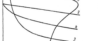
The features of the diode are perfectly illustrated by the current-voltage characteristic, abbreviated as “volt-voltage characteristic”.
In the figure above, areas and types of breakdowns (avalanche, tunnel and thermal) on the return branch are highlighted in red. In the upper right part you see the direct branch of the current-voltage characteristic, i.e. dependence of current on voltage in forward bias.
From it you should understand that almost no current flows through the diode at low voltage, but when it reaches a certain value it begins to flow, and the current strength does not have a linear dependence on the applied voltage (with a small increase in voltage, a strong increase in current occurs), and limited only by load resistance. With reverse bias, practically no current flows (very little) and this continues until breakdown occurs. There are 3 types of breakdown:
Rectifier circuits
In single-phase circuits, one of three alternating current rectification schemes is used, they have the following names:
A half-wave rectifier consists of a diode connected in series with the load. Here, oddly enough, the load Rн receives one half-cycle from the supply voltage, the second half-cycle or the reverse half-wave of the sinusoid does not pass through the diode. The circuit is good in that it only needs one diode, but it has a number of disadvantages: the voltage across the load is reduced by 2 times and the ripple factor is high. To smooth them out, you need a capacitor of unreasonably large capacity, which increases both the dimensions and the final cost of the product.
A full-wave rectifier or diode bridge already consists of four diodes. Here they work “diagonally”, that is, one half-wave is carried out by the upper left and lower right diodes, and the opposite half-wave is carried out by the lower left and upper right diodes (the positions are indicated conditionally, relative to the above diagram). The voltage in the load is equal to the voltage at the bridge input, but it is no longer alternating, but rectified pulsating. To smooth out ripples, a capacitor (one or more connected in parallel) is installed in parallel with the load. In this case, electrolytic capacitors are used due to their large capacity with relatively small dimensions.
The second variant of the full-wave rectifier is the midpoint rectifier. Here, one load terminal is connected to the midpoint of the transformer, and the cathodes of two diodes are connected to the second load terminal. The voltage at the ends of the secondary winding relative to the midpoint is in antiphase (conventionally in the diagram they are designated as Uinput1 and Uinput2).
Since the voltages are shifted relative to each other by half a period and the diodes transmit only one half-wave, the load receives a rectified full-wave voltage Uoutput, as in the previous version. You can see that in the first half-cycle current flows through diode VD2, in the second half the diode closes and current begins to flow through diode VD1.
How to turn a constant into a variable?
A device that converts direct current into alternating current is called an inverter. There are several types of these devices.
Inverter with electric motor
The DC motor shaft is connected to a sliding contact assembly consisting of two parts:
- rotating : consists of several ring and segment plates packaged in the shape of a cylinder;
- fixed : graphite brushes in brush holders.
One pair of brushes is connected to a direct current source, the other to an alternating current circuit. The first pair is in contact with the ring plates, the other with the segment plates.
Some of the latter are electrically connected to the positive ring, the other to the negative ring. As the motor rotates, the brushes of the alternating current circuit contact the segment plates in turn, causing the direction of the current to constantly change. Better quality alternating current is provided by the “DC motor – mechanical generator” combination, but this inverter has lower efficiency.
Relay inverter
Immediately the spring throws the core back to its original position, so that the cathode is connected to the mentioned contact. Such oscillations are repeated many times as long as a direct current is supplied to the solenoid coil.
Electronic inverter
With the advent and gradual reduction in cost of semiconductors, electromechanical inverters have become obsolete.
In their electronic counterpart, the current is redirected by switching transistors controlled by a microcircuit. It is these inverters that are used in inverter welding machines, switching power supplies, UPS, etc.
When using special fast-switching transistors, such an inverter is capable of creating alternating current from direct current with a frequency of tens of kHz. This allows you to reduce the dimensions of the transformer and the losses in it (welding machines, switching power supplies). There are several types of electronic inverters. They are described in the last section.
Selecting an inverter (voltage converter)
An inverter is a device that converts direct current into alternating current, changing the voltage.
Inverters that convert 12 V or 24 V to 220 V are becoming more and more in demand - after all, there are many areas of application for these devices:
And these are not all the situations where an inverter will make your life easier.
If you are already thinking about buying such a device, then you should figure out what types of voltage converters there are, and how to choose the best option for your needs without overpaying extra money.
The first thing you need to decide is why do you need an inverter?
The simplest, miniature and low-power inverters, to the cigarette lighter in cars , organize a “regular outlet” for connecting a low-power device - charging a phone or laptop, recharging a flashlight. In this case, you will not need to carry a bunch of wires with you to power each device from the cigarette lighter. You will simply connect the original wire into an organized outlet.
You should not connect an inverter with a load higher than 150 W through the car cigarette lighter - you can damage the entire electrical wiring of the car and run into expensive repairs. Consumers above 150 W should only be connected directly to the battery, through terminals .
More powerful devices can be connected to such converters. To reduce losses in efficiency and reliability, connecting powerful inverters to the battery terminals should be done not with the “crocodile clips” that are sometimes supplied with the device, but with copper screw terminals. Select the cross-section and length of the connection wires based on the calculation of current losses, and not on heating.
The next thing to pay attention to is the shape of the current that the inverter produces. This is an important point because it determines what equipment you can connect to the inverter. There are two types:
But this does not mean that it is not recommended to use an inverter with a modified sine wave. It will not have a negative impact on the quality of operation of lighting lamps, heating devices, equipment with switching power supplies (laptops, phones), most televisions, power tools with commutator motors (jigsaws, drills). However, to ensure the operation of a power tool from an inverter, it is better to purchase an additional soft starter so that the starting currents do not go beyond the permissible limits.
When choosing an inverter, you definitely need to think about what you want to connect to it, and after that decide whether you are willing to pay for a device with a pure sine wave, or the best purchase for you would be a less expensive device with a modified sine wave.
All voltage converters have two power characteristics - constant power and peak power of the device . It is necessary to distinguish between these two parameters.
Constant power indicates how much load the inverter can handle in long-term operation. Depending on your needs, you can choose a low-power device from 60 to 1000 W, or a serious unit with a power of 1000 W and above, which allows you to organize a mini-power station on the road.
Constant power must be selected in such a way that there is a margin of at least 20% - no device will work well at the limit of its capabilities, so do not skimp on this point. Also, we should not forget about the capabilities of the battery, because its capacity is limited.
Peak power determines the maximum short-term load - from 150 to 10,000 W. For example, the starting current of a refrigerator connected to an inverter is usually several times higher than the rated power - this should be taken into account. If you do not calculate the power of the inverter to cover the starting current, then the consumer device will not be able to start working.
If the inverter will operate from a battery that has not been removed, but is running from the car’s generator, remember that the load current of the inverter should not exceed the output current of the generator.
In fact, selecting the appropriate power is not so difficult, let’s look at an example.
Connected load: refrigerator (15 W), laptop charging (80 W), phone charging (60 W). Here, of course, one should take into account the starting current of the refrigerator, which is 3-4 times higher than the rated current. It turns out that when turned on, the refrigerator will consume (in the worst case) up to 60 W. As a result, we have that for the indicated load, a 300 W inverter is enough for us.
Of course, not all inverters operate with high efficiency; when calculating power, you should add to the load possible losses in the cable, in clamps, etc. - but in general it is clear that a very powerful inverter is not needed to provide the minimum necessary needs. In most cases, for comfortable tourism, a device with a power of up to 600 - 700 W is enough, that is, with a total load current of about 50 A, which is much less than the current of a standard generator on modern cars.
A different situation arises if you want to use an inverter to connect power tools - jigsaws, drills, etc. Here it is advisable to use powerful inverters - from 1 kW and above.
Voltage converters come in different input voltage . Devices up to 2.5-3 kW usually operate from an input voltage of 12 V. More powerful devices, designed to output several kilowatts, are available at higher voltage levels - 24 and 48 V. Therefore, when choosing an inverter, pay attention not only to power , but also on the input voltage parameters:
Almost all inverters are equipped with one or another type of protection that monitors operating parameters and helps to avoid critical situations by triggering a shutdown or sound signal:
To connect the load, voltage converters can have various outputs :
Select a device with the types and number of outputs you need based on what equipment you need to connect. DC outputs with a voltage level of 12 - 28 V will be needed to connect special car equipment: radios, TV receivers, heated seats, car refrigerators). USB ports are useful for charging mobile devices. Outputs in the form of sockets will be required for “universal” connection of electrical appliances. In this case, the types of sockets can be different:
There are also voltage converters that are not designed to connect a 220 V consumer, and convert 24 V to 12 V and 12 V to 24 V - such devices do not have sockets.
Inverters are available in housings made of various materials:
From the point of view of passive cooling, inverters with an aluminum housing are best - it ensures maximum heat dissipation. But for inverters with active cooling (fan in the case), where the problem of heat dissipation is solved, the best option would be a steel case - as it is more durable. Combined cases made of aluminum + plastic or steel + plastic are also a good option, but a case made of only plastic is acceptable only for a low-power device.
Any inverter must be installed in a car in such a way that its cooling is ensured, that is, it should not be closed. Stuffing a working inverter into the glove compartment or case is not the best option.
In the inexpensive price segment up to 1,400 rubles you will find low-power inverters - up to 200 W, with a modified sine wave, designed for connecting to a cigarette lighter and powering small appliances.
In the middle price segment from 1,400 to 5,000 rubles, you will already find more powerful devices - up to 800 W, designed for the most part for connecting to a battery, but still with the same modified sine wave.
In the expensive price segment from 5000 and above, you can find devices with both pure sine and modified ones, but with high power - up to 5000 W.
We can summarize: when choosing an inverter, do not chase the high power of the device, because... all other equipment may not be able to carry such a load. Better pay attention to the build quality, components and materials. A good quality device, even of medium power, will not be cheap. For some types of equipment, an inverter with only a pure sine wave output is suitable. Don’t be lazy to calculate the load before connecting - and you won’t have any unpleasant surprises later.
Video on the topic
How to make alternating current from direct current and vice versa in the video:
Each type of current has both advantages and disadvantages. Therefore, inverters and rectifiers are used quite often. The article shows only the basic converter circuits, but there are quite a lot of them.
V. D. Panchenko, Kiev
Unfortunately, power outages in our homes are becoming a tradition. Will the child really have to do his homework by candlelight? Or just an interesting film on TV, I’d like to watch it through. All this can be fixed if you have a car battery. You can assemble a device called a DC-AC converter (or, in Western terminology, a DC-AC converter) to it.
Figures 1 and 2 show two main circuits of such converters. The circuit in Fig. 1 uses four powerful transistors VT1...VT4 operating in switch mode. In one half-cycle of a voltage of 50 Hz, transistors VT1 and VT4 are open. Current from battery GB1 flows through transistor VT1, the primary winding of transformer T1 (from left to right in the diagram) and transistor VT4. In the second half-cycle, transistors VT2 and VT3 are open, the current from battery GB1 goes through transistor VT3, the primary winding of transformer TV1 (from right to left according to the diagram) and transistor VT2. As a result, the current in the winding of transformer TV1 is variable, and in the secondary winding the voltage rises to 220 6. When using a 12-volt battery, the coefficient K = 220/12 = 18.3.
A pulse generator with a frequency of 50 Hz can be built on transistors, logic chips and any other element base. Figure 1 shows a pulse generator based on the KR1006VI1 integrated timer (DA1 chip). From output DA1, pulses with a frequency of 50 Hz pass through two inverters using transistors VT7, VT8. From the first of them, pulses arrive through the current amplifier VT5 to the pair VT2, VT3, from the second - through the current amplifier VT6 to the pair VT1, VT4. If, as VT1...VT4, you use transistors with a high current transfer coefficient (“superbeta”), for example, type KT827B or powerful field-effect transistors, for example, KP912A, then current amplifiers VT5, VT6 can not be installed.
Read also: Rating of wood splitting axes
The circuit in Fig. 2 uses only two powerful transistors VT1 and VT2, but the primary winding of the transformer has twice as many turns and a midpoint. The pulse generator in this circuit is the same; the bases of transistors VT1 and VT2 are connected to points A and B of the pulse generator circuit in Fig. 1.
The operating time of the converter is determined by the battery capacity and load power. If we allow the battery to be discharged by 80% (lead batteries allow such discharge), then the expression for the operating time of the converter takes the form:
T(h) = (0.7WU)/P, where W is the battery capacity, Ah; U – rated battery voltage, V; P – load power, W. This expression also takes into account the efficiency of the converter, which is 0.85...0.9. Then, for example, when using a 55 Ah car battery with a nominal voltage of 12 V and a load on a 40 W incandescent light bulb, the operating time
will be 10...12 hours, and with a load on a television receiver with a power of 150 W, 2.5-3 hours.
Let us present the data of transformer T1 for two cases: for a maximum load of 40 W and for a maximum load of 150 W.
In the table: S – cross-sectional area of the magnetic circuit; W1, W2 – number of turns of the primary and secondary windings; D1, D2 – diameters of the wires of the primary and secondary windings.
You can use a ready-made power transformer, do not touch the network winding, but wind up the primary winding. In this case, after winding, you need to turn on the mains winding and make sure that the voltage on the primary winding is 12 V.
If you use VT1...VT4 as power transistors in the circuit in Fig. 1 or VT1, VT2 in the circuit in Fig. 2 KT819A, then you should remember the following. The maximum operating current of these transistors is 15 A, so if you count on a converter power of over 150 W, then you need to install either transistors with a maximum current of over 15 A (for example, KT879A), or connect two transistors in parallel. With a maximum operating current of 15 A, the power dissipation on each transistor will be approximately 5 W, while without a heatsink the maximum power dissipation is 3 W. Therefore, on these transistors it is necessary to install small radiators in the form of a metal plate with an area of 15-20 cm.
The output voltage of the converter has the form of multipolar pulses with an amplitude of 220 V. This voltage is quite suitable for powering various radio equipment, not to mention light bulbs. However, single-phase electric motors with a voltage of this form do not work well. Therefore, you should not include a vacuum cleaner or tape recorder in such a converter. A way out of the situation can be found by winding an additional winding on the transformer T1 and loading it onto the capacitor Cp (shown with a dotted line in Fig. 2). This
The capacitor is chosen to be of such a size as to form a circuit tuned to a frequency of 50 Hz. With a converter power of 150 W, the capacitance of such a capacitor can be calculated using the formula C = 0.25 / U2, where U is the voltage generated on the additional winding, for example, at U = 100 V, C = 25 μF. In this case, the capacitor must operate on alternating voltage (you can use metal paper capacitors K42U or similar) and have an operating voltage of at least 2U. Such a circuit absorbs part of the power of the converter. This part of the power depends on the quality factor of the capacitor. Thus, for metal-paper capacitors, the dielectric loss tangent is 0.02...0.05, so the efficiency of the converter decreases by approximately 2...5%.
To avoid battery failure, it does not hurt to equip the converter with a discharge indicator. A simple diagram of such a signaling device is shown in Fig. 3. Transistor VT1 is a threshold element. While the battery voltage is normal, transistor VT1 is open and the voltage on its collector is below the threshold voltage of the DD1.1 chip, so the audio frequency signal generator on this chip does not work. When the battery voltage drops to a critical value, transistor VT1 is turned off (the shut-off point is set by variable resistor R2), the generator on the DD1 chip starts working, and the acoustic element HA1 begins to “squeak.” Instead of a piezoelectric element, a low-power dynamic loudspeaker can be used.
After using the converter, the battery must be charged. For the charger, you can use the same transformer T1, but the number of turns in the primary winding is not enough, since it is designed for 12 V, but at least 17 V is needed. Therefore, when manufacturing the transformer, an additional winding should be provided for the charger. Naturally, when charging the battery, the converter circuit must be turned off.
How to get 12 Volts?
In modern household networks, a huge number of appliances and devices are powered by reduced voltage. As a rule, these are low-current devices that use 12 volts in their power circuit: gas heaters, hand-held power tools, portable and stationary lamps, children's toys and much more.
Due to their widespread use, ordinary people try to organize power for such devices on their own, so in this article we will look at how to get 12 Volts in various ways.
We get 12 Volts from 220
The most affordable power source with a practically unlimited power resource is a household AC voltage of 220 Volts. All that is needed to obtain 12 Volts is to lower, and, if necessary, convert the existing electrical quantity into a constant.
To do this, you can use one of several methods:
Now let's look at each of the methods in more detail.
Method without transformer
If there is no transformer that could lower the network voltage to 12 Volts, you can get by with a regular resistor. The fact is that the voltage drop across a resistor connected in series to a load of 208 Volts will provide 12 Volts on the desired device, provided that the network is 220 Volts.
SILENCER HEAT RECEIVER
Before we look at this topic, let's talk about the rules that need to be followed:
- The power supply unit is designed to work with only one device.
- Each of the external elements must be covered with insulation. Do not touch the electronic circuitry of the unit unless there is a load connected to it or a stabilizer is not connected to it to reduce the DC current.
This sequence cannot cause death, but the unpleasant effects of electricity are guaranteed.
The value of the reducing cooler is determined by the equation:
C (microfarad) = 3200 x I (load) / root of (U input sq. - U output sq.) or C (uF) = 3200 x I (load) / root of U input
It is useless to obtain in other ways, due to the reduction in intensity from 220 to 12 V by a resistor, a lot of heat is generated, and it does not make sense to wind the inductor to obtain the required Volts, because it is very expensive and difficult to implement.
12 Volts from 24 or other higher DC voltage
In addition, there are situations when, instead of a mains voltage of 220 Volts, you have a constant voltage of a higher rating, for example, 24 Volts. A similar situation can arise when motorists want to replace their car battery with a more powerful one from a truck or bus.
For this purpose, a stabilizing element based on the same transistor from which the LED strip is connected can be used.
Example of a 12V from 24V circuit
This is a fairly simple circuit in which the output current will be limited by the characteristics of the transistor. The disadvantage of this option is a slight reduction in voltage if the maximum current for the converter is exceeded. Therefore, in case of an unacceptable result, instead of a transistor, you can use various stabilizers - linear or pulsed. The stabilizer is a more complex device, but the connection diagram will be practically no different, since they are sold as a single unit.
12 Volts from 5 or other reduced DC voltage
We will also not exclude the opposite situation, when from a lower voltage level you can increase it to get 12 Volts. This example is available if there is 5V in the power supply of a personal computer, a charger for a mobile phone, and from all kinds of adapters for a standard network.
To increase constant 5 Volts to a level of 12 Volts, voltage converters are often used. As an example, we will consider a circuit using a converter based on the LM2577 chip. Its advantages lie in the use of a minimum number of components for assembly; there are also several models with a stable output voltage and an adjustable option. The only significant drawback is the rated electric current of 0.8 A.
Example of a 12V circuit from 5V
The picture above shows a simple example of how to get 12 Volts using the LM2577 chip. 5 Volts are supplied from the input terminals through capacitor C1 to inputs 5 and 3 of the microcircuit. The output value from pins 4 and 2 of the microcircuit is regulated by the ratio of resistors R2 and R3. It should be noted that from the practical side, the device turns out to be low-power, so no forced cooling systems or additional radiators are required to be installed for it.
A few words about inverters, or how to make alternating current from direct current
Converting one type of current to another is required quite often. The method of converting AC into DC is simple: a diode bridge and a smoothing capacitor are used.
But not everyone knows how to turn direct current into alternating current. Meanwhile, in the field of electrical engineering, such a transformation, as will be shown below, is also performed quite often.