Flat capacitor
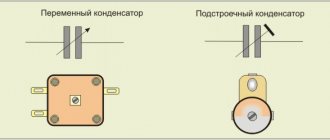
There are many types of capacitors with different shapes and internal structures. Let's consider the simplest and most fundamental - a flat capacitor. A flat capacitor consists of two parallel conductor plates (plates), electrically insulated from each other by air or a special dielectric material (for example, paper, glass or mica).
Capacitor charge. Current
In terms of its purpose, a capacitor resembles a battery, but it is still very different in its operating principle, maximum capacity, and charging/discharging speed.
Let's consider the principle of operation of a flat-plate capacitor. If you connect a power source to it, negatively charged particles in the form of electrons will begin to collect on one plate of the conductor, and positively charged particles in the form of ions will begin to collect on the other. Since there is a dielectric between the plates, charged particles cannot “jump” to the opposite side of the capacitor. However, electrons move from the power source to the capacitor plate. Therefore, electric current flows in the circuit.
At the very beginning of connecting the capacitor into the circuit, there is the most free space on its plates. Consequently, the initial current at this moment encounters the least resistance and is maximum. As the capacitor fills with charged particles, the current gradually drops until the free space on the plates runs out and the current stops completely.
The time between the states of an “empty” capacitor with a maximum current value, and a “full” capacitor with a minimum current value (i.e., its absence), is called the transition period of the capacitor charge.
Characteristics of capacitors
The main characteristic of a device is capacity, that is, the amount of energy that it can accumulate in the form of electrons. The total number of charges on the plates determines the capacitance value of the capacitor.
Note ! The capacitance depends on the area of the plates and the dielectric constant of the material. The larger the area of the capacitor plates, the more charged particles can fit on them and the higher the capacitance.
Capacity
The most important characteristics include specific capacitance, density, nominal charge force and polarity. Additional parameters include the number of phases, capacitor installation method, operating temperature, active electric current of alternating or direct type.
In electrical engineering, there are also concepts of negative factors that distort the operating properties of an oscillatory circuit. These include electrical resistance and equivalent series inductance. An example of a negative criterion is an indicator showing a drop in charge after a power outage.
You may be interested in this All about selectivity
Capacitor charge. Voltage
At the very beginning of the charging transition period, the voltage between the plates of the capacitor is zero. As soon as charged particles begin to appear on the plates, a voltage arises between unlike charges. The reason for this is the dielectric between the plates, which “prevents” charges with opposite signs tending to each other from moving to the other side of the capacitor.
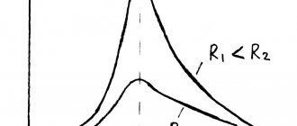
At the initial stage of charging, the voltage rises quickly because the high current very quickly increases the number of charged particles on the plates. The more the capacitor is charged, the lower the current, and the slower the voltage rises. At the end of the transition period, the voltage on the capacitor will completely stop growing and will be equal to the voltage on the power source.
As can be seen in the graph, the capacitor current directly depends on the change in voltage.
The formula for finding the capacitor current during the transition period is:
- Ic - capacitor current
- C - Capacitance of the capacitor
- ΔVc/Δt – Change in voltage across the capacitor over a period of time
Capacitor in AC circuit
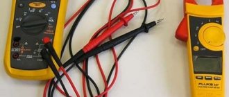
The alternating current in the capacitor is determined using a digital oscilloscope and generator. By applying alternating voltage, the current strength at the input and output of the capacitor is fixed. The oscilloscope monitor shows a graph of current readings and its oscillation amplitude. In this case, the signal is transmitted with some noise. It is radio elements that cause interference, mainly resistors. There is less resistance to alternating current on the side of the capacitor as its frequency increases. This also reduces the phase shift to a minimum. At low frequencies, the phase shift can reach 90 degrees. All of the above suggests that the resistance of the capacitor is interrelated with the frequency of the alternating current, and is calculated as follows:
\(X_C= {1 \over 2}πFC,\)
where \(F\) is frequency;
\(C\) is the capacitance of the capacitor.
If we substitute a zero frequency value into this formula (that is, at constant current), the resistance of the capacitor will tend to infinity, which, in fact, corresponds to an open circuit. This value is called the “high-pass filter”. When using this filter on a capacitor or resistor in audio equipment, a high-pitched squeak will be heard. That is, this filter dampens the bass frequency. Similar types of filters are used in radio electronics devices to jam unwanted frequencies and pass useful ones.
Capacitor discharge
After the capacitor is charged, turn off the power source and connect the load R. Since the capacitor is already charged, it itself has turned into a power source. Load R formed a passage between the plates. Negatively charged electrons accumulated on one plate, according to the force of attraction between unlike charges, will move towards positively charged ions on the other plate.
At the moment of connecting R, the voltage on the capacitor is the same as after the end of the transition charging period. The initial current according to Ohm's law will be equal to the voltage on the plates divided by the load resistance.
As soon as current flows in the circuit, the capacitor will begin to discharge. As charge is lost, the voltage will begin to drop. Therefore, the current will also drop. As the voltage and current values decrease, their rate of decline will decrease.
The charging and discharging time of a capacitor depends on two parameters - the capacitance of the capacitor C and the total resistance in the circuit R. The larger the capacitance of the capacitor, the more charge must pass through the circuit, and the more time the charging/discharging process will require (current is defined as the amount of charge, passed along the conductor per unit time). The higher the resistance R, the lower the current. Accordingly, more time will be required for charging.
The product RC (resistance times capacitance) forms the time constant τ (tau). In one τ, the capacitor is charged or discharged by 63%. In five τ the capacitor is charged or discharged completely.
For clarity, let’s substitute the values: a capacitor with a capacity of 20 microfarads, a resistance of 1 kiloohm and a power source of 10V. The charging process will look like this:
General concept
A capacitor consists of two conductive plates and a dielectric between them. And that's it, nothing more. It looks like a simple radio component, but it works differently at high and low frequencies.
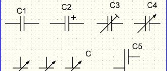
Indicated on the diagram by two parallel lines.
Principle of operation
This radio component demonstrates well the phenomenon of electrostatic induction. Let's look at it with an example.
If you connect a constant current source to the capacitor, then at the initial moment of time the current will begin to accumulate on the plates of the capacitor. This occurs due to electrostatic induction. Resistance is practically zero.
The electric field, due to electrostatic induction, attracts opposite charges to two opposite plates. This property of matter is called capacity. All materials have a capacity. And even for dielectrics, but for conductors it is much greater. Therefore, the capacitor plates are made of conductor.
The larger the capacitance, the more charges can accumulate on the capacitor plates, i.e. electric current.
The main property of a capacitor is capacitance. It depends on the area of the plates, the distance between them and the dielectric material that fills the space between the plates.
As charges accumulate, the field begins to weaken and the resistance increases. Why is this happening? There is less and less space on the plates, like charges on them act on each other, and the voltage on the capacitor becomes equal to the current source. This resistance is called reactive or capacitive. It depends on the frequency of the current, the capacitance of radio components and wires.
When there is no room left on the plates for the electric current, the current in the circuit will stop. Electrostatic induction disappears. Now there remains an electric field that holds the charges on its plates and does not let them go. And the electric current has nowhere to go. The voltage across the capacitor will become equal to the emf (voltage) of the current source.
What happens if you increase the EMF (voltage) of the current source? The electric field will begin to put more and more pressure on the dielectric, since there is no more space on the plates. But if the voltage on the capacitor exceeds the permissible limits, the dielectric will break through. And the capacitor will become a conductor, the charges will be released, and the current will flow through the circuit. How then to use a capacitor for high voltages? You can increase the size of the dielectric and the distance between the plates, but this reduces the capacitance of the part.
Between the plates there is a dielectric that prevents the passage of direct current. This is precisely the barrier to direct current. Because constant current also creates constant voltage. And a constant voltage can create electrostatic induction only when the circuit is closed, that is, when the capacitor is charging.
This way the capacitor can store energy until a consumer connects to it.
Capacitor and DC circuit
Let's add a light bulb to the diagram. It will only light up while charging.
Another important feature is that when the current charging process occurs, the voltage lags behind the current. The voltage seems to catch up with the current, since the resistance increases smoothly as it charges. Electrical charges take time to move to the capacitor plates. This is the charging time. It depends on capacitance, frequency and voltage.
As it charges, the light begins to glow dimmer.
The light goes out when fully charged.
Direct electric current does not pass through the capacitor until it is charged.
AC circuit
What if you change the polarity on the current source? Then the capacitor will begin to discharge and charge again as the polarity of the source changes.
Electrostatic induction occurs constantly if the electric current is alternating. Every time the current begins to change its direction, the process of charging and discharging begins.
Distance between plates
The capacitance of a capacitor is inversely proportional to the distance between the plates. In order to explain the nature of the influence of this factor, it is necessary to recall the mechanics of the interaction of charges in space (electrostatics).
If the capacitor is not in an electrical circuit, then the charged particles located on its plates are influenced by two forces. The first is the repulsive force between like charges of neighboring particles on the same plate. The second is the force of attraction of opposite charges between particles located on opposite plates. It turns out that the closer the plates are to each other, the greater the total force of attraction between charges with the opposite sign, and the more charge can be placed on one plate.
Relative dielectric constant
An equally significant factor influencing the capacitance of a capacitor is the property of the material between the plates as the relative dielectric constant ɛ. This is a dimensionless physical quantity that shows how many times the force of interaction between two free charges in a dielectric is less than in a vacuum.
Materials with a higher dielectric constant allow for greater capacitance. This is explained by the polarization effect - the displacement of the electrons of the dielectric atoms towards the positively charged capacitor plate.
Polarization creates an internal electric field in the dielectric, which weakens the overall potential (voltage) difference of the capacitor. Voltage U prevents the flow of charge Q to the capacitor. Therefore, lowering the voltage helps place more electrical charge on the capacitor.
Below are examples of dielectric constant values for some insulating materials used in capacitors.
- Air – 1.0005
- Paper – from 2.5 to 3.5
- Glass – from 3 to 10
- Mica – from 5 to 7
- Metal oxide powders – from 6 to 20
Formulas for measuring capacitor voltage
The numerical indicator of voltage is equal to electromotive force. It is also defined as the capacity divided by the amount of charge, based on the formula for determining its value. According to another rule, the voltage is equal to the leakage current divided by the insulation resistance.
You may be interested in 1 sq. - how many watts is it?
Basic formulas for calculation
In general, a capacitor is a device for accumulating electrical charge, consisting of several plate electrodes that are separated by dielectrics. The device has an electrode measured in farads. One farad is equal to one coulomb. The voltage of the device is affected by the current, the indicators of which can be calculated using the formulas described above.
Rated voltage
The second most important characteristic after capacitance is the maximum rated voltage of the capacitor. This parameter indicates the maximum voltage that the capacitor can withstand. Exceeding this value leads to “punching” of the insulator between the plates and a short circuit. The rated voltage depends on the insulator material and its thickness (the distance between the plates).
It should be noted that when working with alternating voltage, it is the peak value (the highest instantaneous voltage value per period) that needs to be taken into account. For example, if the effective voltage of the power supply is 50V, then its peak value will be over 70V. Accordingly, it is necessary to use a capacitor with a rated voltage greater than 70V. However, in practice, it is recommended to use a capacitor with a voltage rating of at least twice the maximum possible voltage that will be applied to it.