Basic quantities and units of measurement
There are several basic quantities that define a capacitor. One of them is its capacity (Latin letter C), and the second is the operating voltage (Latin letter U). Electrical capacitance (or simply capacitance) in the SI system is measured in farads (F). Moreover, as a unit of capacity, 1 farad is a lot - it is almost never used in practice. For example, the electrical charge of planet Earth is only 710 microfarads. Therefore, in most cases it is measured in quantities derived from farad: in picofarads (pF) with a very small capacitance value (1 pF = 1/10 6 μF), in microfarads (μF) with a sufficiently large value (1 μF = 1/ 10 6 F).
In order to calculate the electrical capacity, it is necessary to divide the amount of charge accumulated between the plates by the magnitude of the potential difference between them (voltage across the capacitor). The charge of the capacitor in this case is the charge accumulating on one of the plates of the device in question. On 2 conductors of the device they are the same in magnitude, but different in sign, so their sum is always zero. The charge on a capacitor is measured in coulombs (C) and is denoted by the letter Q.
Interesting read: operating principle and main characteristics of varistors.
Formulas for calculating current in a capacitor
The capacitance of a capacitor connected to an alternating current circuit is calculated by the formula: C = q / U, where:
- C - capacity;
- q is the charge of one of the plates;
- U is the voltage inside.
Capacitance
Capacitors come in different shapes, so they are calculated using several formulas:
- flat - C = E × E0 × S / d;
- cylindrical - C=2 π × E × E0 × l / ln(R2 / R1);
- spherical - C = 4 π × E × E0 × R1 × R2 / R2 - R.
Note! The resistance in a variable circuit that a resistor connected to an electrical circuit can provide cannot be calculated, since it is considered infinitely large. However, in this case, this can be done using the formula: Xc = 1 / 2πvC = 1 / wC.
You might be interested in this Description of loading machines
The capacitor voltage in an AC circuit is calculated using the following formula: Wp = qd E / 2.
The voltage is calculated using a certain formula
To calculate the voltage across a capacitor in an AC circuit, you need to use current formulas.
How do they conduct alternating current?
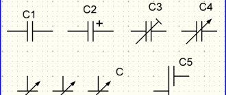
To see this with your own eyes, it is enough to assemble a simple diagram. First you need to turn on the lamp through capacitors C1 and C2 connected in parallel. The lamp will glow, but not very brightly. If we now add another capacitor C3, the glow of the lamp will noticeably increase, which indicates that the capacitors resist the passage of alternating current. Moreover, a parallel connection, i.e. Increasing the capacitance reduces this resistance.
Hence the conclusion: the larger the capacitance, the lower the resistance of the capacitor to the passage of alternating current. This resistance is called capacitive and is denoted in formulas as Xc. Xc also depends on the frequency of the current; the higher it is, the less Xc. This will be discussed a little later.
Another experiment can be done using an electricity meter, having first disconnected all consumers. To do this, you need to connect three 1 µF capacitors in parallel and simply plug them into a power outlet. Of course, you need to be extremely careful, or even solder a standard plug to the capacitors. The operating voltage of the capacitors must be at least 400V.
After this connection, it is enough to simply observe the meter to make sure that it is in place, although according to calculations, such a capacitor is equivalent in resistance to an incandescent lamp with a power of about 50 W.
Capacitor in AC circuit
Let's assemble a circuit with a capacitor in which an alternating current generator creates a sinusoidal voltage. Let's look at what happens in the circuit when we close the key. We will consider the initial moment when the generator voltage is zero. In the first quarter of the period, the voltage at the generator terminals will increase, starting from zero, and the capacitor will begin to charge. A current will appear in the circuit, but at the first moment of charging the capacitor, despite the fact that the voltage on its plates has just appeared and is still very small, the current in the circuit (charge current) will be the greatest.
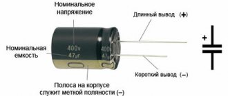
It will be interesting➡ What is the polarity of a capacitor and how to determine it?
As the charge on the capacitor increases, the current in the circuit decreases and reaches zero at the moment when the capacitor is fully charged. In this case, the voltage on the capacitor plates, strictly following the generator voltage, becomes at this moment maximum, but of the opposite sign, i.e., directed towards the generator voltage. Thus, the current rushes with the greatest force into the charge-free capacitor, but immediately begins to decrease as the capacitor plates are filled with charges and drops to zero, fully charging it.
Material on the topic: description and scope of application of the trimming resistor.
Let us compare this phenomenon with what happens to the flow of water in a pipe connecting two communicating vessels, one of which is filled and the other empty. One has only to pull out the valve blocking the path of water, and water will immediately rush from the left vessel under high pressure through the pipe into the empty right vessel. However, immediately the water pressure in the pipe will begin to gradually weaken, due to the leveling of the levels in the vessels, and will drop to zero. The water flow will stop. Similarly, the current first flows into an uncharged capacitor, and then gradually weakens as it charges.
With the beginning of the second quarter of the period, when the voltage of the generator begins slowly at first, and then decreases faster and faster, the charged capacitor will be discharged to the generator, which will cause a discharge current in the circuit. As the generator voltage decreases, the capacitor is discharged more and more and the discharge current in the circuit increases. The direction of the discharge current in this quarter of the period is opposite to the direction of the charge current in the first quarter of the period. Accordingly, the current curve, having passed the zero value, is now located below the time axis.
By the end of the first half-cycle, the voltage on the generator, as well as on the capacitor, quickly approaches zero, and the current in the circuit slowly reaches its maximum value. Remembering that the magnitude of the current in the circuit is greater, the greater the amount of charge transferred along the circuit, it will become clear why the current reaches its maximum when the voltage on the capacitor plates, and therefore the charge of the capacitor, quickly decreases.
With the beginning of the third quarter of the period, the capacitor begins to charge again, but the polarity of its plates, as well as the polarity of the generator, changes to the opposite, and the current, continuing to flow in the same direction, begins to decrease as the capacitor is charged. At the end of the third quarter of the period, when the voltages across the generator and capacitor reach their maximum, the current becomes zero.
In the last quarter of the period, the voltage, decreasing, drops to zero, and the current, changing its direction in the circuit, reaches its maximum value. This ends the period, after which the next one begins, exactly repeating the previous one, etc.
So, under the action of the alternating voltage of the generator, the capacitor is charged twice per period (the first and third quarters of the period) and discharged twice (the second and fourth quarters of the period). But since the alternating charges and discharges of the capacitor are accompanied each time by the passage of charging and discharging currents through the circuit, we can conclude that an alternating current passes through the circuit with the capacitance.
It will be interesting➡ What are flat capacitors
Characteristics of capacitors
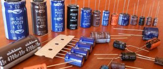
The capacitor, depending on the state of the electrolyte and the material from which it consists, can be dry, liquid, oxide-semiconductor, oxide-metal. Liquid capacitors are well cooled, these devices can operate under significant loads and have such an important property as self-healing of the dielectric upon breakdown. The dry-type electrical devices under consideration have a fairly simple design, slightly less voltage loss and leakage current. At the moment, dry appliances are the most popular. The main advantages of electrolytic capacitors are their low cost, compact dimensions and high electrical capacity. Oxide analogs are polar (incorrect connection leads to breakdown).
How to connect
Connecting a capacitor to a circuit with direct current occurs as follows: the plus (anode) of the current source is connected to an electrode, which is covered with an oxide film. Failure to comply with this requirement may result in dielectric breakdown. It is for this reason that liquid capacitors must be connected to a circuit with an alternating current source, connecting two identical sections in counter-series series. Or apply an oxide layer to both electrodes. Thus, a non-polar electrical device is obtained that operates in both DC and DC networks. But in both cases, the resulting capacitance becomes half as much. Unipolar electrical capacitors are large in size, but can be connected to alternating current circuits. Marking is done with color and digital code. Digital markings of capacitor capacitance are shown below.
Table of digital markings of capacitor capacitance.
Description of DC Capacitor
Electrical circuits are of two types - constant or variable . It all depends on how the electric current flows in them. Devices on these circuits behave differently.
To consider how a capacitor will behave in a DC circuit, you need to:
- Take a DC power supply and determine the voltage value. For example, "12 Volts".
- Install a light bulb rated for the same voltage.
- Install a capacitor in the network.
There will be no effect: the light bulb will not light up, but if you remove the capacitor from the circuit, the light will appear. If the device is connected to an alternating current network, it simply will not close, and therefore no electric current will be able to pass here. Permanent - not able to pass through the network in which the capacitor is connected. It's all because of the plates of this device, or rather, the dielectric that separates these plates.
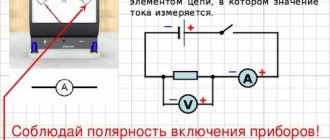
You can make sure that there is no voltage in the direct current network in other ways. You can connect anything to the network, the main thing is that a source of constant electric current is included in the circuit. The element that will signal the absence of voltage in the network or, conversely, its presence, can also be any electrical appliance. It is best to use a light bulb for these purposes: it will glow if there is electric current, and will not light if there is no voltage in the network.
We can conclude that the capacitor is not capable of conducting direct current through itself, but this conclusion is incorrect. In fact, an electric current appears immediately after applying voltage, but disappears instantly. In this case, it passes within only a few fractions of a second. The exact duration depends on how capacious the device is, but this is usually not taken into account.
What is a capacitor used for?
Capacitors are widely used in all electronic and radio circuits. They, together with transistors and resistors, are the basis of radio technology. Application of capacitors in electrical devices and household appliances:
- An important property of a capacitor in an alternating current circuit is its ability to act as capacitive reactance (inductive in the coil). If you connect a capacitor and a light bulb in series to a battery, it will not light up. But if you connect it to an AC source, it will light up. And the higher the capacitance of the capacitor, the brighter it will glow. Due to this property, they are widely used as a filter, which can quite successfully suppress HF and LF interference, voltage ripple and AC surges.
- Due to the ability of capacitors to accumulate charge for a long time and then quickly discharge in a circuit with low resistance to create a pulse, it makes them indispensable in the production of photo flashes, electromagnetic-type accelerators, lasers, etc.
- The ability of a capacitor to accumulate and store electrical charge for a long time has made it possible to use it in elements for storing information. And also as a power source for low-power devices. For example, an electrician's probe, which you just need to insert into a socket for a couple of seconds until the built-in capacitor is charged, and then you can ring circuits with it all day long. But unfortunately, the capacitor is significantly inferior in its ability to accumulate electrical energy from a battery due to leakage currents (self-discharge) and the inability to accumulate large amounts of electrical energy.
- Capacitors are used when connecting a 380 to 220 Volt electric motor. It is connected to the third terminal, and due to the fact that it shifts the phase by 90 degrees on the third terminal, it becomes possible to use a three-phase motor in a single-phase 220 Volt network.
- In industry, capacitor units are used to compensate reactive energy.
AC capacitor.
Operating principle of a capacitor
Connecting the device to a constant source leads to the fact that at the initial moment there is an accumulation in the plates due to electrostatic induction, and the resistance at this moment is equal to zero. Electrical induction provokes a field to attract opposite charges onto different plates located opposite each other.
You may be interested in: Installation and connection of heated floors
This property is called capacitance, which is characteristic of all types of materials, including dielectrics, but in the case of conductors it is significantly greater. That is why the plates are made of conductor. An increase in capacity contributes to the accumulation of more charges on the plates.
Important! When charges accumulate, the field weakens and the two-terminal network increases.
Principle of operation
This happens due to a decrease in space in the plates and the influence of charges of the same name on each other. At the same time, the voltage is equal to the current source. The cessation of electricity in the circuit occurs after the plates are completely filled with electricity. Because of this, induction disappears and only a field remains that holds and does not allow charges to pass through.
Dielectric between plates
The electric current will have nowhere to go, and on a two-terminal network the voltage is equal to the EMF. When the EMF increases, the field acts more strongly on the dielectric due to the lack of space in the plates. If the internal capacitor voltage is higher than the limit values, then the dielectric will break through.
The capacitor is converted into a conductor, and charges are released, causing an electric current to flow. To use a two-terminal network at high voltage, increase the size of the dielectric and increase the distance between the plates while reducing the capacitance. The dielectric is located between the plates and does not allow the constant to pass through, performing a barrier function in relation to it.
Electrical induction
Note! It is direct voltage that can form electrostatic induction, but only in the case of a short circuit at the time of charging the capacitor. Thanks to this mechanism, energy is saved until the consumer is connected to it.
Capacitor in DC circuit
To understand how a storage device works in a DC circuit, you need to add a light bulb to the circuit, which will light up only during charging, during which the voltage remains from the electric current, as if catching up with it due to a smooth increase. Charges of electricity take some time to move to the plates; this is precisely the charging time, the duration of which is determined by the frequency and voltage capacitance. When charging is complete, the light goes out and no constant current flows through the passive electronic component.
Capacitor in AC circuit
If the polarity of the source is changed, this will lead to the discharge of the capacitor in the alternating current circuit and its recharging. A constant electrostatic induction is formed with an alternating one. Whenever electricity changes its direction, the charging and discharging mechanism is triggered, which is why it passes the variable. An increase in frequency leads to a decrease in the capacitive reactance of a two-terminal network.
You might be interested in Transformer differential protection
Capacitor in a constant circuit