One of the elements of an electrical circuit that has a constant (certain) value of resistance to electric current is a constant resistor. Translated from Latin, resisto means “I resist.” With the help of such a part, a linear transformation of current (I) into voltage (U) and vice versa occurs. A resistive element can limit the amount of current and absorb electrical energy. Variable resistors allow you to manually vary the value of their resistance.
Variable resistors, appearance
Potentiometers
A variable resistor (VR) and a potentiometer are two different definitions of one device. At the beginning of the development of radio electronics, it was believed that by changing the position of the moving contact on resistive coils with wire windings, the potential difference was measured. Therefore, two words: “potential” and “measurement” are included in the definition of a potentiometer. This is a variable resistor. Today there are many such components of electronic and electrical circuits, and their names are different. The voltage is adjusted with a potentiometer, and the current with a rheostat.
Important! The operating principle of such elements is the same. They change their output resistance depending on the position of the moving contact or brush, which is driven under the influence of external influences.
Non-wire
Resistors of the SP type belong to composite non-wire elements. They have the following design:
- base made of insulating material;
- film, current-conducting element;
- moving contact;
- axis with moving system.
Non-wire variable resistors also include SPO, VK, SPZ, TK.
A carbon conductive film is applied to the getinax plate (base). Its composition can be composite: bakelite resin and carbon black. The element leads are attached to the ends of the layer. To do this, it is coated with silver paste for contact pads. At specified angular intervals, a slider (moving contact) slides across the film, which is driven from the axis of the resistor.
For your information. The end of the axle is molded for ease of adjustment: a slot (slot) for a screwdriver or a recess for securing the handle.
Non-wire potentiometer device
Resistance may change as the angle of rotation changes. The angle varies from 0 to 2500.
Wire
In resistive variable elements of this type, high-resistance wire is used instead of a conductive film. It is laid in one layer turn to turn. The contact slides along these turns.
Structure of a wirewound variable resistor
A wirewound potentiometer consists of the following elements:
- frame for winding;
- winding;
- unit with an axis of rotation;
- movable brush.
Typically, frames are either bent from plates with wire already wound, or it is wound on rings. The plate frame is made of insulating material or metal.
Attention! Bent plate bases do not have precise geometric parameters, although they are easy to manufacture.
High precision when creating potentiometers is obtained using rings made of ceramic, metal or plastic. In this case, winding is carried out with special equipment - a shuttle, on which the required amount of wire is collected. The wire itself can be nichrome, manganin with enamel insulation.
Interesting. One such wire material is constantan alloy (59% Cu; 40% Ni; 2% Mn). It is an alloy of copper and nickel with the addition of manganese. Edward Weston invented it in 1888 for instrument coils. Constantan resistance is independent of temperature changes.
The wire insulation is ground to a depth of 0.25d. This is necessary for reliable connection of the brush with the winding during movement.
Appearance of the sliding edge
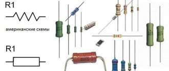
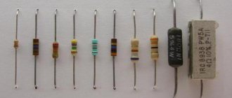
What does a resistor look like?
There are completely different resistors in nature. There are resistors with constant resistance, and there are resistors with variable resistance. And each type of resistor has its own application. To expand on our topic, it is necessary to consider the main types of resistors, because everything is learned by comparison.
It will be interesting➡ How is parallel and series connection of resistors different?
Resistors
Resistors
Resistors
Fixed resistor
A constant resistor has two terminals and the name itself suggests that they have a constant fixed resistance. Each such resistor is manufactured with a certain resistance and a certain power dissipation.
Power dissipation is another characteristic of resistors, just like resistance. Power dissipation tells how much power a resistor can dissipate in the form of heat (you've probably noticed that a resistor can get quite hot during operation).
Naturally, the factory cannot produce absolutely any resistors. Therefore, fixed resistors have a certain accuracy, indicated as a percentage. This value shows within what limits the resulting resistance will vary. And naturally, the more accurate the resistor, the more expensive it will be. So why overpay?
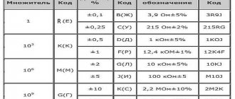
Also, the resistance value itself cannot be arbitrary. Typically, the resistance of fixed resistors corresponds to a certain nominal range of resistances. These resistances are usually selected from the series E3, E6, E12, E24.
| Nominal series | |||||||||||||
| E3 | E6 | E12 | E24 | E3 | E6 | E12 | E24 | E3 | E6 | E12 | E24 | ||
| 1,0 | 1,0 | 1,0 | 1,0 | 2,2 | 2,2 | 2,2 | 2,2 | 4,7 | 4,7 | 4,7 | 4,7 | ||
| 1,1 | 2,4 | 5,1 | |||||||||||
| 1,2 | 1,2 | 2,7 | 2,7 | 5,6 | 5,6 | ||||||||
| 1,3 | 3,0 | 6,2 | |||||||||||
| 1,5 | 1,5 | 1,5 | 3,3 | 3,3 | 3,3 | 6,8 | 6,8 | 6,8 | |||||
| 1,6 | 3,6 | 7,5 | |||||||||||
| 1,8 | 1,8 | 3,9 | 3,9 | 8,2 | 8,2 | ||||||||
| 2,0 | 4,3 | 9,1 | |||||||||||
As you can see, resistors from the E24 series have a richer set of resistances. But this is not the limit, since there are nominal series E48, E96, E192.
On electrical diagrams, fixed resistors are indicated by a sort of rectangle with leads. The dissipation power may be indicated on the conventional graphic designation itself.
Trimmer resistor
These are devices whose resistance is supposed to be changed rarely - when setting up the device and adjusting it. In terms of characteristics, a tuning resistor, in principle, does not differ from a variable resistor, but there are design differences. Trimmer resistors have much lower wear resistance and mechanical strength (after all, they do not need to be constantly “twisted”), there is no convenient handle (instead there may be a regular slot like a screw for a screwdriver), they may be worse or not at all protected from external influences (dust , moisture). They have two and three outputs.
The main purpose of a trimming resistor is to change or adjust the resistance only at the stage of product assembly.
A variable resistor has less accuracy than a constant one. This is a fee for the possibility of adjustment, as a result of which the resistance can vary within certain limits.
Of course, at the stage of setting up the product, a so-called selection resistor can be used. This is an ordinary constant resistor, only during installation it is selected from a bunch of resistors with similar values.
The selection of resistors takes place when adjustment of product parameters is required and high accuracy of operation is required (so that the required parameter floats as little as possible). Thus, it is necessary that the resistor be as accurate as possible, 1% or even 0.5%.
So, to adjust the parameters of the circuit, trimming resistors are most often used. These resistors are specially designed for these purposes. The adjustment is carried out using a thin clock screwdriver, and after reaching the required resistance value, the resistor slider is often fixed with paint or glue.
Variable resistors
Finally, we come to our main topic - variable resistors (aka variable resistance resistors). The name “variable” speaks for itself - the resistance of such a device can be changed during operation in one way or another.
It will be interesting➡ SMD resistors: what are they and what are they used for?
Have you ever paid attention to the various “twists” in old analog technology? For example, have you ever thought about what you turn up when you turn up the volume on an old, perhaps even tube, TV?
Many regulators and various “knobs” are variable resistors. Just like fixed resistors, variable resistors also have different power dissipations. However, their resistance can vary widely.
Variable resistors are used to regulate voltage or current in a finished product. This resistor can adjust the resistance in the sound generation circuit. Then the volume of the sound will change in proportion to the angle of rotation of the resistor knob. So the case itself is inside the device, and that same twist remains on the surface.
Moreover, there are also double, triple, quad and so on variable resistors. They are usually used when a parallel change in resistance is needed in several sections of the circuit at once.
The second name for such resistors is “potentiometers”. They are used so widely that the examples listed above are just the tip of the iceberg. Volume and tone controls, frequency, brightness, speed controls, etc.
Main components
Consists of two main components: a resistive layer and a slider. The resistive layer has contacts at its ends. The resistance between these contacts determines the resistance of the variable resistor. The resistive layer is made of carbon, cermet, or can be in the form of a wire coil (variable wire resistor). Wirewound variable resistors can be quite powerful.
The slider moves across this layer, having electrical contact with it. In this case, the slider also has its own output. As the slider moves from one extreme position to the other, the resistance between it and the extreme contacts of variable resistance changes.
Variable resistances are usually rotary, i.e. The resistor rod must be turned. But there are also slider variable resistors. In them, the resistive layer is in the form of a straight line and the slider moves straight along it. Therefore, the rod of such a resistor must be moved, and not twisted.
Typically, a variable resistor has three outputs. Variable resistors also come with two terminals - they are also called “rheostats”. To understand the three-legged device, let’s look at the picture below.
On the left is the symbol for the resistor, on the right is its “internals” diagram. Pins 1 and 2 are the pins of a conventional constant value resistor indicated on the device body. The resistance is created by a special coating applied to the “horseshoe” between these terminals. There are no tricks here - everything is fair. But pin 3 is connected to a movable plate (engine), which moves along this very horseshoe and comes into contact with it.
If we turn the knob, the resistance between pins 1 and 3 will change from 0 to the value indicated on the device body. The same thing will happen between pins 2 and 3, but upside down. When the resistance between 1 and 3 increases, between 2 and 3 decreases and vice versa. We will look at why this was done later, for now we will take it as a fact, and a very convenient fact, as we will see.
Variable resistor with switch
When using variable resistors as a volume control, for example in a radio, variable resistors with a switch are often used. Those. The volume control is combined with the radio power supply switch. How it works: in the extreme position of the control, when it corresponds to the minimum volume value, the power switch is turned off and the device, in this case the radio, is also turned off.
It will be interesting➡ How to calculate a resistor for an LED?
To turn it on, you need to start turning the knob towards increasing the volume. There will be a slight click - the switch will turn on and further turning of the knob will lead to an increase in the volume of the receiver. In the future, to turn off the device, you need to turn the volume knob to the minimum sound, and then a little more until there is a characteristic click, meaning that the switch has tripped and the device is turned off.
Dual variable resistor
A dual variable resistor is another design of these devices. In general, such dual resistors are designed to simultaneously change the resistance in different independent parts of the circuit or in different devices altogether.
The most common use of dual variable resistors is in stereo audio power amplifiers, where it is necessary to adjust the volume simultaneously in two channels: right and left.
Such resistors have two resistive tracks, each with its own leads and slider, and one common rod that moves both sliders at once.
Some variable resistors are designed to be mounted directly onto a printed circuit board and their contacts are soldered directly into the circuit. Others are designed to be installed into the radio housing, into a pre-drilled hole and secured there with a nut. Such resistances are already soldered into the circuit using wires. On the lane body resistances, the value of its resistance and power is plotted.
Basic PR parameters
Like any element of radio engineering and electronic technology, the potentiometer has its own physical and electrical characteristics. These include the following points:
- Rnom – nominal resistance (total), Ohm;
- Pnom – rated power, W;
- Rmin – minimum resistance value, Ohm;
- functional type of change in resistance;
- wear resistance;
- the amount of noise during adjustment;
- dimensions.
Equivalent resistance
Price and operating features under the influence of various external factors also relate to the characteristics of a passive resistive two-terminal network.
Nominal resistance
As for the marking of a variable resistor, a figure for the value of the nominal resistance is applied to its body, without indicating the permissible deviation (±30%).
Attention! Standard series Rnom for Russian parts (according to GOST 10318-74) – 1.0; 2.2; 3.3; 4.7 Ohm (kOhm, Mohm). For imported elements – 1.0; 2.0; 3.0; 5.0 Ohm (kOhm, Mohm). Exact data for individual brands can be clarified in the directory.
The resistance between pins 1 and 3 is called total or nominal.
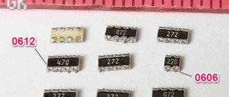
Markings on the body
Functional characteristics form
The change in R between terminals (middle and extreme) can occur according to different laws. This is called functional characteristic (FC). It can take the following forms:
- linear – R changes in direct proportion to the movement of the slider;
- nonlinear - changes occur in a given order.
There are three forms of change in R that can be considered basic:
- linear - A;
- logarithmic – B;
- exponential (inverse logarithmic) – V.
For each of them, a graph is displayed, which is drawn taking into account the angle of rotation of the engine clockwise.
Functional characteristics graphs
Elements that change resistance according to the linear law A are used in voltage dividers. Audio frequency generators (AFGs) include potentiometers in their circuits that use functional characteristic B. Resistors with variable resistance, used in sound reproduction equipment, operate according to law B.
For your information. To obtain the required PC, the components or layer size of the resistive film are changed, and in wire structures, the winding pitch is varied or the frame shape is made with different widths.
The short service life of potentiometers is associated with a violation of the contact density between the slider and the track (wire), which affects the quality of the equipment.
Main characteristics of variable resistors
For stable operation in an electrical circuit, it is necessary to take into account the technical parameters of resistive elements.
Nominal (impedance) resistance
A constant amount of resistance between the fixed contacts; the slider is pulled out all the way and pressed against one of the fixed contacts.
Rated power
The maximum power that a resistor can dissipate as heat under continuous electrical load without changing parameters.
Maximum operating voltage
The maximum operating voltage that can be applied to the terminals of a resistor without destroying the latter. Depends on the length of the resistive element.
Temperature coefficient of resistance
Change in resistance when the ambient temperature changes by one degree.
Tolerance or accuracy
The permissible deviation from the nominal resistance value is from 10 to 30 percent.
Wear resistance
The number of cycles of movement of the moving contact during which the parameters of the variable resistor remain within normal limits.
Important! Trimmer resistors do not have a large number of operating cycles and are not intended for frequent resistance adjustment, unlike variables.
Functional dependence
Dependence of the change in resistor resistance on the angle of rotation of the knob or movement of the slider:
- Linear - a uniform change in resistance when the moving contact moves a certain distance.
- Nonlinear (logarithmic and inverse logarithmic) – a smooth change in resistance at the beginning and end of the slider movement and jumps in the middle.
Designation of functional characteristics:
- A – linear;
- B – logarithmic;
- B – inverse logarithmic.
Noise level
Electrical interference that occurs during the operation of a moving contact depends on the condition (wear) of the contacting surfaces, the degree of pressing of the slider and the speed of its movement.
Designation of variable resistors in diagrams
Resistor - what is it and what is it for?
The graphical appearance of the potentiometer is the designation of a rectangle with leads, with a line with an arrow resting on it. In the imported version, instead of a rectangle, there is a zigzag segment representing turns of wire. This designation can be found when calculating the value of R using an online calculator.
Graphic designation on diagrams
Trimmer resistors
Resistor resistance - formula for calculation
The markings for tuning resistors are the same as for variables. Such potentiometers are used for a limited number of rotations of the engine axis. Their use is associated with the adjustment of equipment and electronic circuits in the setup mode, where it is necessary to adjust certain parameters in the required interval and record the resulting resistance value.
Appearance and graphic designation
Electronics for everyone
It seems like a simple detail, what could be complicated here? But no! There are a couple of tricks to using this thing. Structurally, the variable resistor is designed in the same way as it is shown in the diagram - a strip of material with resistance, contacts are soldered to the edges, but there is also a movable third terminal that can take any position on this strip, dividing the resistance into parts. It can serve as both an overclockable voltage divider (potentiometer) and a variable resistor - if you just need to change the resistance. The trick is constructive: Let's say we need to make a variable resistance. We need two outputs, but the device has three. It seems that the obvious thing suggests itself - do not use one extreme conclusion, but use only the middle and second extreme. Bad idea! Why? It’s just that when moving along the strip, the moving contact can jump, tremble and otherwise lose contact with the surface. In this case, the resistance of our variable resistor becomes infinite, causing interference during tuning, sparking and burning out of the graphite track of the resistor, and taking the device being tuned out of the permissible tuning mode, which can be fatal. Solution? Connect the extreme terminal to the middle one. In this case, the worst thing that awaits the device is a short-term appearance of maximum resistance, but not a break.
Fighting limit values. If a variable resistor regulates the current, for example, powering an LED, then when brought to the extreme position we can bring the resistance to zero, and this is essentially the absence of a resistor - the LED will char and burn out. So you need to introduce an additional resistor that sets the minimum allowable resistance. Moreover, there are two solutions here - the obvious and the beautiful. The obvious is understandable in its simplicity, but the beautiful is remarkable in that we do not change the maximum possible resistance, given the impossibility of bringing the engine to zero. When the engine is in the uppermost position, the resistance will be equal to (R1*R2)/(R1+R2) - the minimum resistance. And at the very bottom it will be equal to R1 - the one we calculated, and there is no need to make an adjustment for the additional resistor. It's beautiful!
If you need to insert a limitation on both sides, then simply insert a constant resistor at the top and bottom. Simple and effective. At the same time, you can get an increase in accuracy, according to the principle given below.
Increased accuracy. Sometimes it is necessary to adjust the resistance by many kOhms, but adjust it just a little - by a fraction of a percent. In order not to use a screwdriver to catch these microdegrees of rotation of the engine on a large resistor, they install two variables. One for a large resistance, and the second for a small one, equal to the value of the intended adjustment. As a result, we have two knobs - one “ Coarse ” and the other “ Precisely ”. We set the large one to the approximate value, and then use the fine one to bring it to perfection.
Including variable resistors in an electrical circuit
The connection diagram for such resistive elements depends on what they are used for. There are two types of connections to circuits:
- as a rheostat - an adjustable resistor to limit current;
- like a potentiometer - for dividing voltage (divider).
In the first case, the middle and extreme conclusions are taken, in the second - the middle and both extreme ones.
Attention! When the rheostat is turned on, the second free lead is soldered to the middle one to ensure more reliable contact.
Manufacturing technology of variable resistors
There is a classification that depends on the resistor manufacturing technology. During the production process, different steps and patterns are used. Today we can distinguish the following designs:
- Wirewound variable resistor. The connection is made using simple technology that even a novice specialist can master. It is wound from wire with high resistivity. In this case, a frame is used. These designs have high parasitic inductance. To significantly reduce this figure, you need to use bifilar winding. Wirewound resistors in some cases can be made of durable microwire.
- Metal film resistors. They are also commonly called composite. They contain a resistive element, which is presented in the form of a thin film. It is obtained from metal alloys or composite materials. Such structures have high resistivity and low thermal resistance coefficient. The wire is applied to cylindrical ceramic cores. Today, this type of element is in particular demand, so people most often ask for a composite variable resistor. The connection is made using any of the methods described above.
Determining the type by marking
The marking is adopted in accordance with GOST 11.074.009-78 and has its own interpretation.
The designation of alphanumeric resistor labels (from left to right) is as follows:
- letters RP – variable;
- numbers: 1 – non-wire, 2 – wire or metal foil;
- registration number;
- year of issue;
- FH type;
- nominal resistance value;
- letter of tolerance for deviation from the nominal value.
The number of marks applied depends on the size of the case, but the Rnom value is required.
Decoding the markings on the body
Variable resistors can be of different designs. It is allowed to install several variable resistive elements on one axis. They are used to adjust and adjust many electrical parameters.
Schemes for all occasions
In addition to the basic characteristics inherent in all types of resistors , variable resistors have several specific characteristics. Namely: Functional dependence (control curve), resolution, rotation noise, static friction torque and wear resistance. Let's look at each characteristic in more detail.
Functional dependence (regulation curve). The control curve shows the dependence of the resistance value between the moving contact and one of the fixed contacts of the conductive element on the angle of rotation. According to the nature of the functional dependence, variable resistors are divided into linear and nonlinear. The nature of the nonlinear dependence is determined by the circuit problems for which the resistor is intended. The most common nonlinear dependencies are logarithmic and inverse logarithmic. Resistors with such dependencies are used to adjust the volume and timbre of sound, the brightness of electronic tubes, etc. There are also resistors with sine, cosine and other dependencies used for special purposes in drives of various devices.
Deviations from a given curve are determined by tolerances (boundaries). For variable resistors of general use (SP, SPO, SPZ, SP4, SPb, etc.), these limits are set within 5-20%, and for precision potentiometers (PTP, PLP, PMP, etc.) within 0.05-1 %. Deviation from the functional dependence may have an abrupt nature, as a result of which the smoothness of regulation is disrupted. The reasons for such deviations may be inhomogeneity and defects of the conductive element and moving contact, as well as the presence of an initial jump and minimal resistance.
The functional dependence is checked using a device with an oscilloscope and a standard variable resistor or by measuring the resistance corresponding to the specified position of the moving contact of the resistor being tested.
Resolution . An important characteristic of variable resistors is the resolution, which shows what is the smallest change in the angle of rotation of the moving resistor system that can be distinguished. It is characterized by the minimum permissible change in resistance with a very small movement of the moving contact. Quantitatively, resolution is expressed as the ratio of the jump in resistance or voltage when the moving system is rotated to the total resistance or to the total voltage supplied to the resistor.
For non-wire resistors, the resolution is theoretically unlimited and is limited by defects in the conductive layer, contact brush and the value of the transition contact resistance. The resolution of variable wire resistors depends on the number of turns of the conductive element and is determined by the movement of the moving contact at which the resistance value (set value) changes. Therefore, resolution is often expressed in angular quantities. This is the angle through which the movable contact must move in order to move from turn to turn (angular degree of the winding).
The angular resolution with a uniform winding pitch is equal to: Δy=a/n, where a is the total winding angle; n is the number of turns. The greater the number of turns at a given operating voltage, the smaller the voltage surges and the higher the resolution. If the moving contact touched only one turn of the winding, then the value of the smallest increment in the output voltage U would be equal to U0/n, where U0 is the voltage supplied to the resistor and n is the total number of turns. Then the so-called electrical resolution, expressed as a percentage, will be equal to: Δ=(U/U0)*100%=(1/n)*100%
The resolution of general-purpose variable resistors ranges from 0.1 to 3%, single-turn potentiometers from 0.02 to 0.4%, and multi-turn potentiometers from 0.001 to 0.2%.
Rotation noises . In addition to thermal and current noise when the moving resistor system rotates, a component is superimposed on the output voltage, which depends on the rotation angle, - the rotation noise voltage. Their level significantly exceeds thermal and current noise in the resistor and reaches 30 - 40 dB. Rotation noise is especially common with wirewound potentiometers. Rotation noise can come from:
- Transition resistance noise resulting from the appearance of a contact potential difference between the brush and the resistive element.
- Thermoelectromotive force arising from the heating of a conductive element during rapid rotation of a moving system.
- Inhomogeneity of structure and defects in the conductive layer and contact brush.
The reasons for the noise of wire resistors can also be a short circuit of adjacent turns by a moving contact when it moves, a stepwise change in resistance, heating of the moving contact and winding wire and the occurrence of thermo-emf, heterogeneity of metals of the contact pair, etc.
The noise of a short circuit is due to the fact that the moving contact, having a certain width, closes either one or two turns when moving. It is proportional to the current passing through the winding and the transition resistance.
The noise, determined by the stepwise nature of the change in resistance , is caused by voltage surges between individual turns when the moving contact jumps from one turn to another. The interference created by this noise appears as a sawtooth voltage superimposed on the output voltage. Its amplitude is directly proportional to the supply voltage and inversely proportional to the number of turns of the winding. The frequency of the fundamental noise harmonic is proportional to the speed of movement of the moving contact and the number of turns of the winding.
Noise is measured using sound level meters with continuous rotation of the axis at a speed of 60-80 cycles/min.
Contact noise and contact resistance noise occur when current passes through a contact resistance. It manifests itself as a result of a change in the effective area of the moving contact and modulation of the current density, perceived as noise. Noise caused by changes in contact resistance appears as chaotic voltage peaks. The main reasons for this type of noise are: incorrect selection of materials and design of the contact-resistive element pair, contamination on the resistive element, oxide films and wear products that create additional resistance between the sliding contact and the resistive element.
Active (generator) noise is caused by the thermoelectric effect (thermocouple effect) that occurs at the points of contact of different metals, the thermoelectric effect that occurs during friction of two metals, and galvanic (chemical) process at the points of contact joints. This noise is a self-generating voltage when the resistor shaft rotates when no electrical voltage is applied to it.
Mechanical noise appears in dynamic mode from excessively large (from several Ohms to infinity) transition resistance. This noise is sometimes called vibration noise. The reasons for this may be large mechanical loads and high rotation speed of the moving system, leading to vibration changes in the state of the contacts. If the critical sliding speed is exceeded, the moving system loses contact with the resistive element, and a voltage surge may occur, reaching the voltage supplied to the resistor.
The previously used parameters starting torque and torque (the minimum torque required to set the resistor shaft in motion is the starting torque, and the minimum torque required to ensure continuous movement of the moving system after the start of its movement is the rotation torque) are essentially drive parameters, not a resistor.
The rotation of the movable resistor system and the movement of the movable contact along the current-carrying resistive element are more correctly characterized by the moment of static friction . The moment of static friction of the moving system of a variable resistor is the moment caused by the friction forces in the moving parts of the resistor and is numerically equal to the moment applied to the resistor shaft to ensure the start of movement of the moving resistor system from any position.
The value of the static friction moment depends on the method of fastening, the design of the elements of the moving system and the contact pressure. For variable resistors of different types, it can be from units to hundreds of gram-centimeters. The static friction moment can be measured using devices with a pulley and a load, a special spring, or in an inertia-free method using mechatrons.
Wear resistance . Wear resistance is understood as the ability of a resistor to maintain its parameters (resist wear) during repeated rotations of the moving system. This is one of the main operational characteristics of variable resistors. Wear resistance is quantified by the number of cycles of movement of the moving system during its service life while maintaining stability of parameters within established tolerances and is determined mainly by the design, material and shape of the moving contact and resistive element and contact pressure.
When the moving system rotates, wear occurs both on the resistive element itself and on the contact brush. This wear process is more intense, the greater the contact force. It follows that to increase wear resistance it is necessary to reduce the contact pressure, but in this case, due to a decrease in the torque of the moving system, the resistance to mechanical stress decreases. Therefore, it is very difficult to meet the requirement of high wear resistance while maintaining mechanical resistance.
Precision potentiometers operating in servo systems are characterized by low contact pressures and correspondingly low torques. Their wear resistance reaches 105 - 107 turns, but at the same time, vibration and shock resistance is lower than that of resistors for general use. Regulating resistors for general use have good mechanical resistance, but their wear resistance is lower and ranges from 5000 to 20,000 turns. For trimmer resistors, since they are used for one-time adjustments, high wear resistance is not required; the number of cycles of movement of the moving system for them does not exceed 1000.
List of used literature
- Resistors: Directory / V.V. Dubrovsky, D.M. Ivanov, N.Ya. Pratusevich and others; edited by I. I. Chetvertkova and V. M. Terekhova. — 2nd ed., revised. and additional - M.: Radio and Communications, 1991.
- Handbook of a young radio operator. V.G. Bodilovsky. - M.: Higher School, 1983.
Video
Coffee capsule Nescafe Dolce Gusto Cappuccino, 3 packs of 16 capsules
1305 ₽ More details
Coffee capsules Nescafe Dolce Gusto Cappuccino, 8 servings (16 capsules)
435 ₽ More details
Rechargeable batteries