August 24, 2011
Bulk Metal Foil technology was developed in 1962 by Dr. Felix Zandman, founder of Vishay. The company's work resulted in foil resistors with a low temperature coefficient of resistance (TCR) and high stability of parameters regardless of temperature changes [1]. Bulk Metal Foil technology introduced the company to the market of precision resistors and devices based on them and made it one of the clear leaders in this field.
Z-Foil technology successfully implemented in 2000, became a new breakthrough for Vishay. For the first time, an absolute TCR value of ±0.2 ppm/°C was achieved.
The company's development strategy [2] is focused on vertical integration of products - the use of technology for manufacturing foil resistors for sensors (resistance, strain, current, etc.); the use of sensors in electronic measuring devices; integration of sensors and electronic measuring devices, as well as software into modules and measuring systems.
Main properties of Vishay resistors and their range
Today, foil resistors are superior to other types of resistive components in accuracy, stability and reliability. All this became possible thanks to a unique design, including the use of a special resistive alloy (C-Foil, K-Foil, and since 2000 - Z-Foil), which provides unique properties - extremely low temperature and power resistance coefficients (TCR and MCR less than 10 ppm /°C) [3-5].
Typical technical characteristics of foil resistors:
- Low temperature coefficient of resistance: ±0.05ppm/°C (0...60°C), ±0.2 ppm/°C (-55...125°C);
- Wide range of rated power;
- High maximum operating voltage 180V;
- High accuracy ±0.01…0.001%;
- ISS as a result of self-heating 5ppm at rated power;
- Electrostatic protection up to 25 kV;
- Stability when operating under load ±0.005% (70°C, about 2000 hours of operation at rated power);
- Wide range of nominal resistances;
- Non-inductive, non-capacitive design;
- Low current noise values -40dB;
- Voltage ratio less than 0.1ppm/V;
- Operating temperature range -55…125°C;
- Possibility to produce ANY (1K892346) rating within the resistance ratings of this series.
The company offers precision resistors for almost any application, in any design [3, 5]. The range of foil resistors (Table 1) includes:
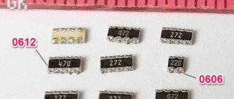
- Surface Mount Resistors (SMD);
- Discrete resistors for through-hole mounting;
- Voltage dividers (through-hole and SMD);
- Resistor assemblies (for through-hole and SMD mounting);
- Current-sensing resistors;
- Sealed resistors;
- Potentiometers;
- Hybrid chips;
- Sealed resistor assemblies to customer order;
- High temperature resistors (operating temperature over 220°C);
- Resistors for audio.
Table 1. Vishay Precision Group range of foil resistors
| Surface Mount Resistors | Appearance | Lead resistors and assemblies | Appearance |
| VSMP Series | VH Series | ||
| VFCP Series | Z201 | ||
| SMRxD Series | VHP Series | ||
| VCS2516Z | VPR Series | ||
| CSM Series | VHA Series | ||
| PRND | VCS Series | ||
| DSM/SMN | VFP Series | ||
| VSM | S Series | ||
| VFCD | 300144 |
As a service, Vishay offers a unique Prototype Fastlane (PFS), which allows the consumer to receive Bulk Metal Foil technology resistors of any value (for example, 123.455487 Ohms) within 76 hours.
Fixed resistors
The main parameter of a constant resistor is the nominal resistance, which can change during operation under the influence of various factors.
This change must occur within controlled limits. In other words, such a change must be calculated at the design stage.
There are several possible reasons for such a standard change: rounding and manufacturing errors, temperature effects of the environment, self-heating of the resistor, aging, parameter changes after overloads. Let's give some explanations.
A resistor is a serial product and is produced with a limited number of nominal resistance values. The denomination is selected in accordance with the tables (given below). When choosing, we are forced to round the value we need to the nearest serial value, thereby introducing some error at this stage. The second component of the error is the inaccuracy in the manufacture of the resistor, which is stated by the manufacturer in technical documents.
But this is not enough: the resistance of the resistor changes under the influence of the environment. The most powerful destabilizing factor in this case is temperature. The characteristics of the resistor specified in technical documents make it possible to calculate and take into account such a change. It should also be borne in mind that the resistor itself heats up when current flows through it.
When using precision (especially precise) resistors, such self-heating can lead to significant metrological errors. Another case, less controllable: the resistance changes after the resistor is overloaded. Overload is a phenomenon when an electrical (electronic) circuit briefly operates in abnormal mode at increased operating voltages and/or currents.
Such modes do not yet lead to destruction of the circuit, but the parameters of the components change somewhat. Partial degradation of precision resistors can lead to significant metrological distortions. It can be reduced at the production stage.
To do this, the manufacturer conducts thermal training of resistors for some batches or on order.
So, let's take a closer look at the main characteristics of constant resistors.
Precision manufacturing of nominal values of resistors
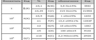
Manufacturing accuracy is described by the relative manufacturing error (tolerance), expressed as a percentage: δ=100ΔRnom/Rnom.
Serial resistors are manufactured in a wide range of accuracies: from the coarsest ±20% (rarely used; usually for variable resistors) to precision ±0.01% (used in measuring instruments). The most widely used resistors are those with a tolerance of ±5%. They are produced with nominal values that correspond to the E24 series (presented in Table 1.2).
The number 24 in the name of the series is the number of distinguishable production values among, respectively, units, tens and hundreds of Ohms, as well as kOhms, MOhms....
For example, with a distinguishable value of 2.4, resistors of the following ratings are produced: ... 2.4 Ohm; 24 Ohm; 240 Ohm; 2.4 kOhm; 24 kOhm, 240 kOhm; 2.4 MOhm, etc.
Table 1. 2 – Row E24 nominal values of resistors
| E24 | |||
| 1.0 (initial) | 1,8 | 3,3 | 5,6 |
| 1,1 | 2,0 | 3,6 | 6,2 |
| 1,2 | 2,2 | 3,9 | 6,8 |
| 1,3 | 2,4 | 4,3 | 7,5 |
| 1,5 | 2,7 | 4,7 | 8,2 |
| 1,6 | 3,0 | 5,1 | 9.1 (final) |
Resistors with a tolerance of ±1% or less are usually considered accurate and precision. They are produced in accordance with other series: E48, E96 and/or E192 (presented in Table 1.3).
Table 1.3 – Rows E48, E96, E192 of nominal values of precision resistors
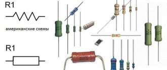
Resistor markings
Modern resistors have relatively small overall dimensions. It is difficult to place identification marks on their surface (nominal resistance, tolerance, TKS, type).
For widely used cylindrical resistors, an international designation has been introduced and is widely used. So, to mark low-precision resistors, four colored stripes, rings or dots are used (shown in Figure 1.6): the first two stripes specify a two-digit nominal value from the E24 series.
The third bar is the decimal multiplier, and the fifth is the percentage tolerance. A fifth color stripe (not shown) is added to the marking of precision and precision resistors. There are markings with seven stripes.
For chip resistors, the dimensions of which are even smaller than cylindrical ones, three- or four-digit digital markings are used, which may differ from one manufacturer to another. Typical marking of low-precision chipresistors (2%, 5%, 10%) is carried out using three digits, where the value is calculated by multiplying the first two digits taken from the E24 series by 10 to the power equal to the third digit.
For example, the number 273 means 27k ohms, the number 270 means 27 ohms, and the code 2R7 means 2.7 ohms.
Rated power dissipation
This is the kind of power that can be dissipated by a resistor indefinitely. In this case, the resistor will not fail under the influence of the released thermal energy. Manufacturers produce resistors in wide power ranges. For our purposes, resistors with a power range from 2 W to 0.062 W are of interest.
The power dissipated in the resistor is calculated using the formulas P=U2/R = I2R. The overall dimensions of resistors are also related to power dissipation: all other things being equal, the dimensions of more powerful resistors are larger. Table 1.4 shows the dimensions of domestic cylindrical resistors C2-29V for comparison.
Table 1.4 – Overall dimensions of resistors C2-29V
| Parameter | Rated power dissipation, W | |||||
| 0,062 | 0,125 | 0,25 | 0,5 | 1,0 | 2,0 | |
| Length, mm | 6,5 | 8 | 11 | 11 | 20 | 28 |
| Diameter, mm | 2,3 | 3,5 | 4,5 | 4,5 | 9,8 | 8,6 |
When choosing a resistor power, keep the following notes and recommendations in mind:
- when using resistors in AC circuits, power dissipation and rated power are calculated based on the rms value of the applied voltage;
- it is necessary to select the rated power of the resistor with a 20% margin so as not to reduce the functional reliability of the resistor. If a resistor dissipates its rated power during operation, the service life of the resistor is reduced;
- in some cases, the rated power of precision resistors is selected with a 10-fold margin. Only in this case will self-heating of the resistor not lead to unacceptable nominal errors;
- As the ambient temperature increases, the permissible power dissipation by the resistor decreases. The technical documentation provides a graph of the dependence of the permissible power on the ambient temperature;
- when the power dissipation is close to the rated one, the resistor may be quite hot to the touch - this is not yet a sign of its emergency operation;
- All other things being equal, higher resistance resistors should be selected, keeping in mind that they will dissipate less power, increasing the efficiency of the circuit.
In order to increase the information content of circuit diagrams, resistor graphemes are often used, in the body of which their rated powers are indicated in accordance with GOST 2.728-74 (shown in Figure 1.7).
Maximum operating voltage
This parameter should usually be taken into account when using high-resistance resistors. The fact is that in the expression P=U2/R, with the selected permissible Pnom and an increase in Rnom, the voltage value U=√(Pnom/Rnom) increases sharply. For example, with Pnom = 1 W and Rnom = 1 MOhm, we have U = 1000 V.
If the selected resistor belongs to the group of widely used resistors (not special ones), then it is a mistake to assume that such a voltage can be applied to it without consequences - the resistor will definitely fail as a result of dielectric breakdown. It is important that in our case, at the rated dissipation power, thermal breakdown will not occur, but dielectric breakdown (interturn) will occur.
The maximum operating voltage, as well as the rated power, depends on the dimensions of the resistor (shown in Table 1.5).
Table 1.5 – Limit operating voltage of resistors C2-29V
| Parameter | Rated power dissipation, W | |||||
| 0,062 | 0,125 | 0,25 | 0,5 | 1,0 | 2,0 | |
| Limit working voltage, RMS, V | 150 | 200 | 350 | 500 | 700 | 750 |
Temperature coefficient of resistance
This parameter allows you to calculate the maximum change in nominal resistance under the influence of temperature. TKS (KT) is usually measured in units [ppm/ºC], where ppm is read as “part per million”.
Let the TCR of some resistor be equal to ±100 ppm/ºC. This means that when the temperature changes by 1ºC, its nominal resistance changes (increases or decreases) by one hundred parts per million. For precision resistors, it is useful to represent this change also in %: multiply by 100 and get ±0.01%/ºС.
Formula for calculating the maximum change in the nominal value of a resistor under the influence of temperature ΔRT.п= KT ×Rnom×ΔT, where ΔT=|20ºС - Tmedium|. 20ºС – normal temperature (temperature at which the nominal value is set).
Example: let Rnom= 10 kOhm, ΔT=20-5 = 15ºС, KT=±100 ppm/ºC.
We have: ΔRT.п= (100/106)× 10,000 × 15 = ±15 Ohm.
Typical design ratios
- Ohm's law: R=U/I (1.1)
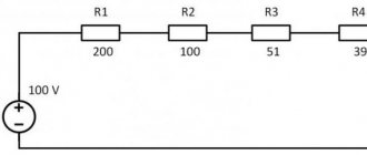
- Generalized Ohm's law (Ohm's law for a section of a circuit): I=(Uba+E1 - E2)/(R1+R3+R2) (1.2)
3. Series connection of resistors Re = R1+R2+R3
4. Parallel connection of resistors Re = R1*R2/(R1+R2)
5 Useful expressions to simplify the calculation of Re for a number of practical cases:
Rab= Ra+Rb+Ra*Rb/Rc ; Ra= Rca*Rab/(Rca+Rab+Rbc)
Areas of use
The characteristics of foil resistors allow them to be used in areas with a high degree of responsibility, increased requirements for quality, accuracy or service life, as well as in harsh climatic conditions - medical equipment, high-performance audio equipment, precision measurement systems, aerospace or military applications [3, 5, 6].
Bridge circuits
This type of application requires four resistors - three are built using the most stable technology, and the fourth acts as a sensing element, converting the value of a physical quantity into a change in voltage at the output of the bridge circuit. In this case, the resistors are mounted as close to each other as possible, and they also try to make their temperature the same during measurements. Foil resistors are ideal for this application due to their exceptionally low temperature and power coefficient of resistance, low thermoEMF noise, and short charge resorption time.
Current sensors
A very low resistance four-point resistor minimizes power loss across the measuring resistance and uses thermal radiation to measure current. Measuring very large currents with this method requires the resistor to be large enough to dissipate heat. Vishay Foil technology resistors are an excellent solution because... a thin flat layer of foil is placed on a ceramic substrate, which is able to dissipate and transfer sufficient heat to the underlying board. A low TCR prevents the resistor parameters from drifting when the temperature changes due to heating when a large current flows.
Differential Amplifiers
The gain of a conventional amplifier should be as constant as possible regardless of environmental conditions. The input resistor and feedback resistor in these circuits have excellent characteristics of heat dissipation and current flow, heating the resistors. In a differential amplifier we are talking about four, and sometimes more, resistors - this means that they all must exhibit almost identical characteristics over a wide range of values. Vishay Bulk Foil technology resistors meet these requirements better than others.
Gyroscopes in navigation systems
Electrostatic gyroscopes use electronic control to realign the gyroscope as its orientation changes. Other types of gyroscopes are also critical to the accuracy of the resistors used in their circuits. Most often, resistor assemblies are used in circuits, used to determine and implement the functions “on-off”, “azimuth control” and others. These functions are critical from the point of view of controlling aircraft, watercraft, and spacecraft. This is just one of the reasons why the use of precision foil resistors is almost mandatory.
Pressure Sensors
Air pressure in aircraft and submarines is typically a matter of life and death, requiring high accuracy and even greater reliability from measurement systems. Most often, the output of the sensor depends on the force applied to it, and for accurate signal processing, a bridge circuit is required, the resistance values of which are in the middle range of values, which minimizes power consumption and, accordingly, heating of the resistors. Foil resistors in such circuits, in addition to temperature, add temporary stability of parameters.
Switching power supplies
This application requires resistance sets with minimal reactance. Any parasitic inductance or capacitance in the resistors can negatively affect the circuit's performance by affecting the switching edge slope. Due to their design and manufacturing technology, Vishay Foil resistors have minimal reactivity compared to others.
Telecommunications
In telecommunications infrastructure, the most important parameters are a wide operating frequency range and high time stability. The design of Vishay foil resistors is planar with adjacent conductors carrying current in opposite directions. This solution reduces the inductance of the resistor, and the parasitic capacitances are connected in parallel, which reduces the resulting capacitance - all this reduces the reactive component of the resistor impedance and improves its frequency characteristics.
Medicine
In this area, foil resistors ensure stability of parameters even under conditions of variable temperature and humidity. The main applications include: cardiographs; tomographs; miniature sensors for 3D imaging systems for intramural diagnostics and surgery; implants.
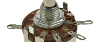
Variable adjustment resistors
Variable (regulating) resistors are designed for intensive adjustment, as is done when changing the volume in audio amplifiers.
The main characteristic of such resistors is the type of dependence of the resistance on the regulatory action (angle of rotation of the shaft or movement of the engine). Three types of dependence are implemented (shown in Figure 1.8): A – linear, B – logarithmic and C – inverse logarithmic.
Variable resistors have different design solutions. But all of them must ensure that the control rod (shaft) is brought out through the device body. The design principle of variable resistors and the functional prototype (rheostat) are presented in Figures 1.9a, 1.9b.
a) – the principle of design of variable resistors;
b) – functional prototype (rheostat);
c) – i) – differences between variable resistors according to the method of fastening in the device using a nut and thread on the device body;
j) – n) – differences between variable resistors according to the method of soldering into the printed circuit board and additional fastening also using a union nut;
n) – a variable resistor as a constructive imitation of a rheostat when soldered into a board.
Figure 1.9 – Design types of variable resistors
Design differences are related to the method of mounting variable resistors in the device:
- some are fastened with a nut and thread on the device body, connection with the electrical circuit is realized using hanging conductors (shown in Figures 1.9c ... 1.9i);
- others are soldered into the printed circuit board and additionally secured using a union nut (shown in Figures 1.9k ... 1.9n);
- still others are soldered into the board and structurally imitate a rheostat (shown in Figure 1.9p), in which the change in resistance is carried out not by rotation of the shaft, but by the translational movement of the engine, brought out.
Other possible differences are the type of resistive material: wire or layer of wear-resistant conductor.
Note - Typically, resistance adjustment is carried out according to a linear law: uniform movement of the armature (engine) leads to a uniform change in resistance.
To adjust the volume in audio amplifiers, adjustment is carried out according to the logarithmic law. In our devices, the second method is not used.
Characteristics of variable resistors.
The characteristics are similar to those of fixed resistors:
- rated resistance, rated power, maximum operating voltage, TKS, design features and overall dimensions. But there are also specific parameters:
- range of change (regulation) and minimum set value;
- accuracy of resistance setting;
- guaranteed number of full revolutions without changing characteristics, etc.
As an example, let's look at the general view and main characteristics of an adjustment resistor of type PTD901-2015K-B103, which are shown in Figure 1.10.
Variable resistor connection diagrams
There are two ways to connect variable resistors: rheostatic and potentiometric (shown in Figure 1.11).
Literature
1. G. Kell. Vishay Intertechnology: portrait of the company // Electronics News No. 9/06, pp. 23-25.
2. Vishay Precision Group. Company Overview. // https://www.vishaypg.com/docs/75012/vpg_co.pdf
3. Ultra-High-Precision Bulk Metal® Foil Resistors. Advanced Medical Applications, Treatment Solutions, and Biotechnology // https://www.vishay.com/docs/49466/pl_cap_b.pdf
4. Introduction to High Precision Resistors. Vishay Foil Resistors// https://cimail15.blh.com/docs/49787/intro.pdf
5. Bulk Metal® Foil Resistors. Complete resource guide.// https://images.vishaypg.com/vpgdocs/49789VMN-PL0373.pdf
6. 10 Technical Reasons Why to Choose Foil Resistors for Your Circuit Vishay Foil Resistors // https://vishaypg.com/docs/49788/10reasns.pdf
7. Thermal EMF for Low Ohmic Value Resistors // https://www.vishay.com/docs/30175/thermal.pdf
8. Yuval Hernik. Component selection and layout strategies for avoiding thermal EMF.// https://www.eetimes.com/design/power-management-design/4214897/Component-selection-and-layout-strategies-for-avoiding-thermal-EMF.
Obtaining technical information, ordering samples, delivery - e-mail
•••
Standard range of resistor powers and their designation in diagrams
Do not forget that resistor components of the same value can have different powers. It all depends on the creation technique and the material of the body. Below is a number of capacities and their official designation.
| W | Symbol on electrical circuits |
| resistor component power 0.05 W | As signed on the diagram 0.05 V. |
| element power 0.125 W | resistor power 0.125 Watt. |
| power 0.025 W | how an element with a power of 0.25 W is highlighted in the diagram |
| power 0.5 W | Thus, a 0.5 Watt resistor is allocated in the circuit. |
| power 1 W | resistor power 1 V. |
| power 2 W | resistor dissipation power 2 W. |
| resistor element power 5 W | this releases 5 W of power |
Graphic coding of resistor powers on an electrical circuit - dashes and Roman symbols. The smallest typical value is 0.05 Watt, the maximum is 25 Watt, but there are more powerful ones. How to indicate the power of weak parts must be remembered. These are oblique lines on rectangles that mark resistance. With resistance values from 1 Watt, certain Roman symbols are displayed on the diagram: I, II, III, and so on. The numerical designations highlight the power of the resistor component in watts. Read about how to determine the resistance of a resistor by color here.