When power goes out for even a few minutes, businesses can suffer enormous losses. And for hospitals this situation is simply dangerous. Most facilities require uninterrupted power supply. To do this, it must be connected to several sources of electricity. Specialists with this approach use AVR.
What is an AVR and its purpose?
Automatic transfer switching or ATS is a system related to electrical switchboard input and switching distribution devices. The main purpose of the ATS is to quickly connect the load to backup equipment. Such a connection is necessary when problems arise with the supply of electricity from the main power source. The system monitors the load voltage and current and thus ensures automatic switchover to emergency operation.
ATS is necessary if there is a spare power source (an additional line or another transformer). If during an emergency the first source is turned off, all work will transfer to the spare one. Using an ATS will help you avoid troubles caused by power outages.
Requirements for ATS
The main requirements for ATS systems are as follows:
- It must have a high rate of power restoration.
- In the event that the main line stops working, the installation must provide electricity to the consumer from a backup source.
- The action is carried out once. Multiple switching on and off of the load, for example due to a short circuit, should not be allowed.
- The main power switch must be turned on using the automatic transfer system. Until backup power is supplied.
- The ATS system must monitor the correct functioning of the backup equipment control circuit.
ATS circuit on one contactor.
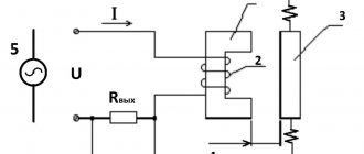
Let's consider the simplest ATS circuit, which can be used for a single-phase network in your own home, small industrial or administrative building. The circuit is made on one contactor KM1
, two single-pole circuit breakers
SF1
and
SF2
, and one double-pole circuit breaker
QF1
.
When you turn on the ATS for the first time, turn on the SF1
and
SF2
.
In operating mode,
the supply voltage from the main input is supplied to the contactor coil
KM1
.
The contactor is triggered and its normally open contact KM1.1
closes, and the normally closed contact
KM1.2
opens.
Phase A1
through the single-pole switch
SF1
and the power contact
KM1.1
it comes to the input of the double-pole switch
QF1
.
Zero N
is not broken anywhere, but is immediately connected to the second input of switch
QF1
.
When QF1
, its contacts close, and the main input voltage is supplied to the network to the consumer.
In emergency mode
, when there is no voltage at the main input, the contactor coil is de-energized, contact
KM1.1
opens, and
KM1.2
becomes closed.
Now from the backup input phase A2
through switches
SF2
,
QF1
and contact
KM1.2
it goes to the consumer in the network.
When power is restored at the main input to the coil of the contactor KM1
The voltage is supplied again and the contactor is activated.
In this case, contact KM1.1
closes, and
KM1.2
opens, and voltage from the main input is supplied to the consumer again.
There are situations when, during normal operation, it becomes necessary to transfer the load power from the main input to the backup one. To do this, just turn off the circuit breaker SF1
.
This ATS circuit is classic and works great, but when using it, it is necessary to take into account the switching power of the power contacts: if the contacts are designed for an operating current, for example, 12 Amps, then the load to the ATS should be connected to no more than 12 Amps
.
In the case when the total power consumption, for example, at home, is more than 12 Amperes, then only the most necessary electrical equipment can be powered from the backup input, which will ensure normal life until the voltage is restored at the main input.
However, in this embodiment, the circuit is suitable only for facilities where it is possible to receive two independent supply voltage lines from the substation. At home, we don’t have this luxury, so we’ll slightly modify the scheme to adapt it to a home network.
Operating principle of automatic reserve entry
The basis of the ATS operation is monitoring the voltage in the circuit. Control can be carried out using any relays or microprocessor control units.
Reference! A voltage control relay (also called a volt controller) monitors the state of the electrical potential. In the event of an overvoltage in the network, the volt controller will instantly de-energize the network.
The contact group, which controls the availability of electricity, plays a major role in the automatic transfer system. In our case it is a relay. When the voltage disappears, the control mechanism receives a signal and switches to power to the generator. When the main network begins to operate normally, the same mechanism switches the power back.
Connecting ATS
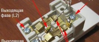
Before making the connection, it is necessary to correctly place all the parts in the electrical panel. They are installed in such a way that there are no crossings of conductors and free access to contacts and terminals is provided. After this, the power part of the ATS and controllers are connected in accordance with the circuit diagram.
Switching of the power part and controllers is carried out using contactors. After all connections, the ATS is directly connected to the generator. The correctness and quality of connections and connections of conductors and other elements is checked using a multimeter.
When using the normal mode, when the voltage is supplied from a regular power line, the automatic transmission system for the generator is activated in the ATS system and the first magnetic starter is turned on, supplying voltage to the switchboard of a private house. With the onset of emergency mode, in which there is no voltage in the network, a relay is used to turn off magnetic starter No. 1 and send a signal to the generator to perform autostart. After the generator starts operating in the ATS panel, the second magnetic starter is triggered, through which voltage begins to flow to the distribution panel of the home electrical network.
Operation in this mode will continue until the main supply of electricity appears or until the generator itself runs out of fuel. When the main voltage is turned on, the generator and magnetic starter No. 2 are turned off, and magnetic starter No. 1, on the contrary, is turned on, and the entire system returns to normal operation.
Installation of an automatic transfer switchboard is carried out after the electric meter. Thus, while the generator is operating, electricity consumption is not taken into account. In addition, the ATS shield for the generator is installed before the main switchboard of the home network. As a result, it ends up installed between the electricity meter and the distribution board.
If the total power of consumers available in the house exceeds the capabilities of the generator or the unit itself is not powerful enough, only those devices and equipment that are really necessary to ensure the normal functioning of the facility are connected to its line until the main power supply is turned on.
Basic options for the logic of ATS operation
ATS system with first input priority
The essence of the operation of this type of automatic transfer system is that the load is initially connected to power source No. 1. When an overload, short circuit, phase loss or other emergency occurs, the load switches to a backup source. When the electricity supply at the first is restored to normal parameters, the load is automatically switched back.
ATS system with second input priority
The logic of operation is the same as that of the previous type of system. The difference is that the load is connected to input 2. In the event of an accident, the voltage goes to input 1. After the voltage on the second source is restored, the voltage will automatically switch to it.
What is AVR
This is a block consisting of several nodes, which automatically switches the load between the main and backup current sources. Some single-phase and three-phase models of gasoline and diesel generators are equipped with an automatic transfer switch initially. To switch the load, you only need to install a special switch after the electric meter. The position of the power contacts is controlled by the main power source.
Almost all models with a battery-powered power plant can be equipped with autonomous ATS systems. In this case, ATS cabinets are used to install backup input units. In this case, ATS panels (Figure 1) can be placed directly next to gas generators or the units can be installed in a common electrical panel.
Figure 1. Example of an ATS electrical panel
The main function of the AVR unit is to automatically start the power plant after the disappearance of electric current in the general network, and then connect the load to the backup power supply. When the power supply is restored by the automation unit, the load is switched to the main electrical network, and the backup source is turned off.
Classification of ATS devices:
- by the number of reserve sections;
- voltage class;
- type of backup network (use in single-phase networks or for three-phase consumers);
- power of the served load;
- switching delay time.
The electrical circuit of the ATS can be configured in such a way as to provide energy not to the entire local network, but only to those lines that are critical. Some schemes allow you to take into account the priority of lines. First of all, power is provided to those circuits that provide electricity to important life support systems. This approach allows you to rationally distribute the load.
Main types of AVR cabinets and panels
ATS panel for two inputs on contactors (starters)
Installing an ATS cabinet on starters is the easiest way to create backup power. This cabinet is the most budget-friendly option for installing an ATS. As a rule, automatic switches are used in ATS cabinets with 2 inputs. They are needed to protect the system from overloads and short circuits. Protection against phase imbalance and voltage surges is provided by a voltage relay. In addition, the relays become the “brains” of the entire automatic transfer system.
An ATS cabinet with two contactors works according to the following principle. Two contactors are connected to the first and second sources, respectively. The first contactor is closed, and the second has an open circuit. Electricity goes through input No. 1.
Attention! In the case when the ATS has priority logic for the second input, the situation will be the opposite: the circuit of the second contactor is closed, and the first one is open.
If the current supply at the first input disappears, but at the second it is normal, then the contacts of the second starter will close and the mechanism will switch to it. As soon as the voltage is restored at the first input, the circuit will return to its original state.
Using a relay, here you can adjust the delay time with which switching from one source to another will take place. The optimal delay is from 5 to 10 seconds; it will protect the system from false triggering of the automatic transfer switch. False triggering can occur, for example, in the event of a voltage dip.
Reference! To prevent both contactors from turning on at the same time, additional mechanical interlocks are used in ATS panels.
ATS panel for 2 inputs on motor-driven machines
They are best suited for use with current ratings of 250-6300A. When the current at the main input disappears, special electric motors receive a signal and charge the springs of the spare switch, switching the load to another input.