Work in industrial enterprises requires the implementation of an automatic control system. For this purpose, various equipment is used that can ensure the uninterrupted functioning of production machines. To control metal objects, non-contact inductive sensors are often used, which have both positive and negative qualities. But the main thing is that they are small in size and perfectly perform their assigned functions, which is why they are popular among manufacturers of household and even medical equipment.
General description and purpose
An inductive sensor is usually called a device capable of converting the mechanical movements of controlled objects into an electrical signal. It is one or more inductance coils combined with a magnetic circuit and a moving armature, which records measurements of linear or angular size and, moving, affects the inductance indicator, changing it in one direction or the other. Thanks to this feature, non-contact sensors are actively used as elements for monitoring the position of metal objects.
Kinds
According to the construction scheme, induction sensors are usually divided into only 2 separate types: single and differentiated.
Single
Devices with only one magnetic core. This scheme is usually used when developing contactless switches.
Differential
They are distinguished by the presence of two magnetic circuits at once, each of which is specially made in the form of a “w”. This makes it possible to compensate for the effect on the core, thus increasing the accuracy of the measurements taken. Essentially, the circuit is a system of two sensors connected by a common armature.
DEVICE, CHARACTERISTICS, PRINCIPLE OF OPERATION
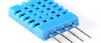
Inductive (or contactless) sensors, despite their different specifics, have a similar internal structure. A metal or plastic case filled with a compound (electrical insulating composition based on epoxy resins, polymers, bitumen), inside there is an EMF generator, a trigger (in analog devices a detector), a status indicator (LED), and a signal amplifier.
The generator consists of a semiconductor element that produces a current of a certain frequency, which through an inductor with a ferrite core creates an alternating magnetic field.
When a conductive material (metal signal flag or other actuator) enters the sensitivity zone of the sensor, the inductance of the system changes, in turn affecting the amplitude of the generator current. Upon reaching the response values, a control signal is generated at the trigger.
The amplifier increases the pulse power to the required values, after which, depending on the purpose of the device, it is supplied to the switching unit (opens - closes the circuit) or further, to the measuring instrument or automatic control system.
Based on their design, sensors are divided into:
- single - with one magnetic circuit, measurement branch. The circuit is implemented in contactless switches;
- differential - with two w-shaped magnetic circuits, mutually compensating the effect on the core, which increases the sensitivity and accuracy of measurements. In essence, they are a system of two single sensors with a common armature;
- transformer - the transformation ratio changes when the armature moves, generating a certain voltage at the output of the secondary winding. The principle is used in elements for fixing angular and small linear movements.
Inductive sensors operate on both direct current (voltage 12, 24, 42, 60 V) and alternating current (up to 220 V). Characterized by the following parameters:
- maximum current;
- switching frequency - for most models up to 1-5 kHz;
- response limit - the minimum value of a physical quantity that causes a response;
- response speed (in microseconds);
- climatic version - the temperature range at which the device is guaranteed to operate (from -400C to +600C).
The advantages of inductive elements over similar devices of other operating principles are:
- reliability of the design - no moving elements, no contacts, complete tightness, strength;
- service life up to 10 years, do not require any maintenance;
- high sensitivity, speed and frequency of operation;
- output signal power up to 100 W and above;
- availability, wide choice of types and manufacturers.
Flaws:
- demanding on “cleanliness” and constancy of the supply current;
- sensitive to external magnetic fields, the output signal may be distorted.
Device and circuit
An induction sensor, like any electronic device, consists of interconnected components that ensure uninterrupted operation. The main elements of the device are the following.
Generator
The key task of the generator is to create a magnetic field, on the basis of which, in particular, the operating principle of the induction sensor is based, and also the formation of activity zones with the object.
Schmidt trigger
The Schmidt trigger is a separate element, the main purpose of which is to provide hysteresis during the switching process of the device.
Amplifier
An amplification device is used as an element capable of increasing the value of the pulse amplitude, which allows the signal to reach the required parameter faster.
Special indicator
LED indicator indicating the actual state of the controller. In addition, the LED is used to provide sufficient control over the functioning of the induction sensor, as well as to ensure sufficient efficiency in the setup process.
Compound
The compound is intended to protect the device, since it can prevent liquids, in particular water, from entering the induction sensor housing, and also reduces the risk of contamination of the equipment, since dust can cause its breakdown.
Principle of operation
The principle of operation is based on changes in the amplitude value of the oscillations of the generator unit when an object of a certain size enters the active zone of the device. In the process of supplying power to the end of the equipment, a changing magnetic field is formed in the area of its sensitive part. It induces eddy currents in the material located in the working area of the sensor, leading to a change in the amplitude of electromagnetic oscillations.
As a result, an output signal will begin to be generated, which may change during the process depending on the actual distance between the device and the monitored object.
CAPACITIVE SENSORS
The operating principle of an electronic capacitive sensor is based on changing the capacitance of a flat or cylindrical capacitor depending on the movement of one of the plates. An indicator such as the dielectric constant of the medium between the plates is also taken into account.
One of the advantages of such devices is their very simple design, which allows them to achieve good strength and reliability.
Also, meters of this type are not subject to distortion of indicators due to temperature changes. The only condition for accurate indicators is protection from dust, humidity and corrosion.
Capacitive sensors are widely used in a wide variety of industries. The devices are easy to manufacture, have low production costs, and at the same time have a long service life and high sensitivity.
Depending on the design, devices are divided into single-capacity and spirit-capacity. The second option is more difficult to manufacture, but is characterized by increased measurement accuracy.
Application area.
Most often, capacitive sensors are used to measure linear and angular displacements, and the design of the device may vary depending on the measurement method (the area of the electrodes or the gap between them changes). To measure angular displacements, sensors with a variable area of capacitor plates are used.
Capacitive transducers are also used to measure pressure. The design provides for the presence of one electrode with a diaphragm, which bends under pressure, changing the capacitance of the capacitor, which is recorded by the measuring circuit.
Thus, capacitance meters can be used in any control and regulation systems. In energy, mechanical engineering, and construction, linear and angular displacement sensors are usually used. Capacitive level transmitters are most effective when working with bulk materials and liquids, and are often used in the chemical and food industries.
Electronic capacitive sensors are used to accurately measure air humidity, dielectric thickness, various strains, linear and angular accelerations, ensuring accuracy in a wide range of conditions.
Options
To control the functionality of the induction sensor, as well as determine the level of its signals, you need to understand the device parameters.
Supply voltage
Represents the permissible voltage range within which the device operates correctly.
Minimum switching current
This is the minimum possible value of electric current that must flow to the sensor to ensure its operation.
Working distances
This is the maximum permissible distance from the device to an iron square of millimeter thickness. However, this value decreases if a different material is used.
Switching frequency
This is the maximum possible number of switches that can be made within one second.
Connection method
The connection option for any contactless sensor depends on the construction scheme used during its production.
Three-wire
Three-wire ones have 3 conductors, 2 of which are intended to provide power to the device, and the third is used to connect to the load. It, depending on the structure used in the development, can be connected to the anode or cathode of an electric current voltage source.
Four-wire
Four-wire induction sensors are distinguished by the presence of four conductors: 2 wires go to power, and the other 2 to loading.
Two-wire
Two-wire devices are connected directly to the load circuit. This is the most basic option, but it also has its own special features. This method requires a nominal resistance for the load, but if its value is greater or less, then the induction sensor will not be able to work correctly.
Attention! When connecting the device to a DC power source, be aware of the polarity of the terminals.
Five-wire
The five-wire differs from the four-wire only in the presence of a fifth conductor, which allows you to select the operating mode of the device.
Inductive sensor parameters
One of the parameters has already been described above - this is the response range. Although, according to experts, it is not important, it is precisely on this basis that the choice is made. The thing is that the product passport indicates the nominal voltage parameters when the device operates at a temperature of +20C. Direct voltage is 24 volts, alternating voltage is 230 volts. As you understand, in such conditions the induction sensor usually does not work, and if it does, it rarely works. In this case, the object that will change the inductance of the device coil should be a steel plate; its width should be equal to three response ranges and 1 mm thick.
Color coding
All electrical equipment, including conductors, must be color coded. It is customary to apply it for the convenience of subsequent installation work and further maintenance. This rule must also be observed in the case of induction sensors. Their output conductors are marked with the following colors:
- minus is usually indicated in blue;
- plus - red;
- exit - black;
- white - additional output or control input, which is determined by the type of sensor used.
Errors
Errors in the process of converting diagnostic values affect the ability of induction sensors to provide reliable information. The main ones include the following.
Electromagnetic
This error is usually taken into account only as a random variable. As a rule, it occurs during the induction of EMF in the induction coil as a result of external influence by external magnetic fields. This occurs during the manufacturing process due to power electrical devices. They form magnetic fields, which subsequently forms an electromagnetic error.
From temperature
This error also acts as a random value, since the operation of a large number of elements of the induction sensor directly depends on temperature indicators, so this is a key quantity that is even taken into account in the design process of such equipment.
Magnetic elasticity
Typically, such an error can manifest itself as a consequence of instability in the deformation of the magnetic circuit of the device during the assembly of the sensor itself, as well as during deformation changes during operation. In addition, the effect of unstable electrical voltage on the magnetic circuit of the equipment causes a decrease in the quality of the transmitted signal at the output.
Deformation of elements
This error, as a rule, manifests itself as a result of the influence of the measuring force on the deformation value of the parts of the induction sensor, as well as under the influence of forces exerted on unstable deforming processes. In addition, it can be equally influenced by backlashes and gaps formed in the moving elements of the device’s structure.
Cables
Such an error usually manifests itself from an unstable resistance value, in the case of deformation of the wire itself and under the influence of temperature. Also, interference from external EMF fields in the cable can have a similar effect.
Aging
This error can manifest itself when the moving elements of the device itself wear out, as well as in the case of constantly changing magnetic properties of the magnetic circuit used. It is generally considered to be, strictly speaking, a random value. In the process of determining this error, the kinematics of the induction sensor design are taken into account, and during the design of such equipment, it is recommended to determine the maximum operating life only when operating in normal mode, so that wear does not have time to exceed the set value.
Technologies
Technology errors appear in the event of deviations from the technical production process, with a clear scatter in the technical parameters of the coils and other elements during assembly, or the influence of the allowed gaps when connecting the device. To measure it, it is customary to use mechanical measuring equipment.
Areas of use
The possible area of application of induction sensors is so wide that it allows them to be used not only in everyday life and the automotive industry, but also in industry with robotics, as well as medicine.
Medical devices
Inductive sensors are widely used in the production of medical equipment, since the magnetic properties of the device make it possible to record pulmonary ventilation, vibration parameters, and also take ballistocardiograms.
Appliances
In everyday life, sensors can act as a device for monitoring water supply, lighting level and door position (closed or open), therefore they are used in the production of, for example, washing machines and other household appliances. In addition, the devices are used in the process of creating smart home elements.
Automotive industry
An induction sensor is also used in the automotive industry, acting as a controller that determines the position of the crankshaft. When a metal object, in this case a gear tooth, approaches the device, the magnetic field generated by the built-in permanent magnet increases, which leads to the induction of an alternating voltage in the coil.
Attention! Some manufacturers are trying to change the design of the induction sensor to improve efficiency, for example, using external magnets to activate it.
Robotic equipment
In the case of robotics, inductive sensors have found application in the production of unmanned vehicles and industrial robots to increase their sensitivity to obstacles and the ability to recognize objects, as well as devices for which self-balancing is important.
Industrial control and measurement technology
They are widely used in the operation of conveyor systems, packaging machines and assembly lines, as well as as part of all types of machine tools and shut-off valves. Inductive sensors also help to monitor small and large elements of industrial equipment (gear teeth, steel flags, stamps), production objects (metal products, metal sheets, covers), etc. In addition, when connected to pulse counters, the result is a rudimentary but extremely effective reading device.
Possibility of using inductive position sensors
Contactless inductive switches are designed to work with metal objects. Thanks to this, the devices can be actively used in various types of machines, machine tools and mechanisms to control the position of individual elements. The sensors are ideal for automatic control processes and production automation.
In addition, inductive sensors can be used to work with individual metal objects in various industries:
- mechanical engineering;
- metallurgy;
- production of machines and equipment;
- woodworking;
- food industry;
- transport industry;
- agriculture and many others.
A number of manufacturers also offer special versions, for example for explosion-proof applications, elevated pressure and temperature, and other non-standard conditions.
Next generation induction sensors
Thanks to new developments in this area, improved models of next generation induction sensors have been created. The principle of operation remains the same, but the design of the device has been thoroughly redesigned. As a result, sensors are now equipped with thin 3D printed circuit boards and advanced digital electronics. In addition, they are produced on flexible substrates, eliminating the need for traditional cables and connectors. So you can use the devices even in difficult weather conditions.
The advantages of new developments include the following:
- reduced cost and weight, more compact dimensions;
- the ability to choose almost any form factor;
- increasing the accuracy of response to metal objects;
- the ability to take measurements involving complex geometries in two or three dimensions;
- simplification of design;
- the ability to install several induction sensors close to each other due to high electromagnetic compatibility.
All this made it possible to increase the efficiency and availability of the device, as well as expand the scope of its application.
So what is this “trick” - an inductive proximity sensor?
The principle of operation, circuit design, and features of two types of inductive proximity sensors - generator and resonant - are considered. A brief description of the modern European market of inductive proximity sensors is given.
In the 50s of the twentieth century, in the era of discrete packaged electronic components, an original oscillator circuit was developed, made with only four or five transistors, which is still successfully used today and marked the beginning of the production of small-sized inductive sensors in millions of copies, the main purpose of which is to create a logical (binary) electrical signal when a metal object (target) approaches the sensor at a short distance (usually this distance ranges from fractions of a millimeter to one hundred millimeters).
These inductive sensors turned out to be a very accessible, simple, reliable, cheap element of control systems for drives, machine tools, automatic lines, and systems for measuring physical quantities. Perhaps dozens, if not hundreds, of companies around the world have grown up in the production of these elements of process control systems - inductive proximity sensors. For example, in the USA in 1990, at least 35 companies were engaged in the production of such sensors. According to the magazine “Control Engineering Europe”, the global market for proximity sensors was estimated at 2.7 billion Euros in 2002 and its growth is 5% per year (meaning the entire market for proximity sensors: inductive, optical, capacitive, ultrasonic, magnetic ), and the European proximity sensor market is worth 1 billion Euros. According to this magazine, the main manufacturers of electronic proximity sensors are: ABB, Balluff, Banner, Baumer Electric, Bernstein, Carlo Gavazzi, Datasensor, ifm electronic, Leuze, Pepperl + Fuchs, Schmersal, Schneider, Sick, Siemens, Turck (listed in alphabetical order).
It is clearly seen that the backbone is made up of German companies, and this is one of the “building blocks” of the leadership of German mechanical engineering in the world. If we narrow this list down to the three most important manufacturers of inductive sensors in Germany, the places will be distributed as follows: 1st place ifm electronic; 2nd place Pepperl + Fuchs; 3rd place Balluff.
Companies specializing in the production of inductive sensors produce a huge range of up to a thousand or more standard sizes. Some operational and technical parameters of inductive proximity sensors indicate the perfection of the manufacturer’s technology:
- the sensors are housed in housings with a diameter of 3 mm with a full range of functions (built-in LED, output protection against short circuit and incorrect power connection, housing protection degree not lower than IP 67);
- the sensors have an all-metal body, i.e. the sensitive surface of the sensor is covered with metal;
- high degree of protection (sealing) of the housing, for example, IP 68, IP 69K. With IP 69K protection, the sensor and electrical connector can be treated with hot water spray under pressure (up to 100 bar);
- production of sensors with a so-called correction factor equal to 1. That is, the sensor, at almost the same distances, determines the approach of different metals to it: carbon steel, stainless steel, copper, aluminum, etc.;
- release of sensors with analog output, when a measuring analog signal is created at the sensor output, proportional to the distance between the sensor and the object;
- production of sensors that can withstand high pressures (200, 300, 500 bar);
- production of sensors operating at very low (up to −60 °C) or very high (up to +180…200 °C) temperatures;
- maximum switching frequency of the output binary (relay) signal is 5, 7, 10 kHz.
The reliability of serial inductive sensors is such that their special versions are used in the most critical places related to the safety of people: TPs that are dangerous for personnel or, for example, in automated control systems of modern ropeways.
The sensor production technology is so mature that manufacturing companies guarantee service life of up to three to five years. For example, ifm electronic indicates a five-year warranty in its catalogues. The service life of sensors can be 20 years or more. Moreover, this has already been tested in practice, since entire production facilities, purchased as a set from Germany in the 80s of the twentieth century and equipped with such sensors, are still operating to this day.
The circuitry of modern inductive proximity sensors is varied and can differ significantly from their “ancestors” of the mid-twentieth century. For example, to automate the control of large technological complexes or complex machines, it is necessary to install dozens and hundreds of inductive and other sensors. In this case, a new generation of two-wire sensors with an AS-i (actuator - sensor interface) interface can provide tangible benefits on communication lines, when up to 248 sensors are connected to one two-wire copper bus. At the same time, the same bus supplies power to sensors, actuators and receives information from sensors. Essentially, one sensor with an AS-i interface is a microcontroller with its own data transmission system.
But still, the originality of the generator circuit - the “primary source” of modern inductive proximity sensors, the richness of the circuit’s functionality, and its simplicity are impressive. Let’s look at this scheme, evaluate where it all began, where several Russian, and even earlier, many foreign companies “rose.”
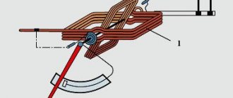
One of the variants of this scheme is shown in Fig. 1
Rice.
1 Inductive proximity sensor of the generator type “Nail” circuit - an oscillation generator on a VT1 transistor assembly with a two-winding inductive sensing element. The parameters of two inductive coils placed on one core, capacitors and resistors are calculated and selected so that when power is connected, oscillations spontaneously occur in the generator. Moreover, the advantage of the generator is its ability to oscillate over a very wide range of supply voltages. This results in a wide range of permissible supply voltages in many inductive sensors: 10...30 V DC. The design of inductors can be very diverse: windings placed in an armored core; windings wound on a core of arbitrary shape; two standard DM type cores connected to each other; just windings without cores. The cores only concentrate and redistribute leakage fluxes in the space around the windings. Most manufacturers use a cup core to concentrate most of the flow into the open cup area. Here the maximum sensitivity of the generator to the approach of metals will be observed. However, the main thing is to select the parameters of the oscillatory circuit so that oscillations occur when the power is turned on.
Now, if a metal object or any material (target) in which eddy currents can be induced is brought close to the coils, then the ability of the oscillatory circuit to oscillate sharply drops due to the mutual induction of the coils and the target. If you continue to bring the coils closer to the target, the oscillations will practically stop or their amplitude will decrease several times. Thus, the sensitivity of the generator to the approach of a metal or magnetic material is very high, which is also an important advantage of the circuit. At the collector 7 of the transistor assembly there is already a demodulated signal, which is supplied to the comparator - a Schmitt trigger on transistors VT2, VT3. Since the collector 7 has an analog signal that is functionally dependent on the distance between the coils and the approaching object, it can be used for measurement purposes, i.e., determining this distance. The comparator creates a relay (binary) amplified output signal. The generator circuit is named because the sensitive element of the circuit is the generator: there are oscillations in the generator - the target is outside the sensitive zone of the coils, the oscillations are disrupted - the target is inside the sensitive zone. LED VD1 will light up and supply voltage will be applied to the load when the target is close to the sensing element. Companies now practically do not produce sensors without indicator LEDs built into the housing. Such an LED in the output circuit is convenient for installing the sensor and monitoring its performance. In the case of an inductive nature (for example, a relay), the load should be shunted with a VD3 diode in order to eliminate parasitic surges in the sensor output signal. Diode VD2 performs the important function of protecting the entire circuit from incorrect power polarity. The disadvantage of such a generator circuit of an inductive proximity sensor is the different switching distance of the sensor for different target materials - the so-called reduction coefficient. Manufacturers usually list it in their catalogs for materials made of steel, aluminum, and brass.
The authors of an article at the Moscow Energy Institute (1988) developed another inductive proximity sensor operating on the resonant principle, i.e., an inductive small displacement sensor. The resonant principle of operation for sensitive elements of photo sensors was proposed even earlier and showed itself well in electronic measuring equipment for the Moscow Olympics (1980).
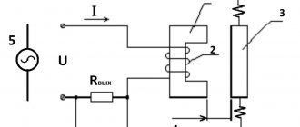
A schematic diagram of a resonant inductive proximity sensor is shown in Fig. 2
Rice.
2 Inductive proximity sensor of resonant type The sensitive element of the sensor is a coil with core L1, which, together with capacitor C1, forms a parallel resonant circuit powered by an RC carrier frequency generator.
In Fig. 1 sensitive element (two coils with a core) is an integral part of the carrier frequency generator. In the two described circuits, the shape of the oscillations (sinusoidal, rectangular or other) does not matter much. In a resonant circuit (see Fig. 2), carrier oscillations are created by an adjustable RC generator consisting of two elements of the 564LN2 microcircuit. The carrier oscillations through the isolation resistor R2 enter the resonant circuit L1-C1. The resonance frequency of the circuit must be within the range of adjustment of the generator by resistor R1. At the resonance frequency, the internal resistance of the parallel resonant circuit is greatest. Therefore, the amplitude at the gate of field-effect transistor VT1 is maximum. A real LC circuit also has side resonances, but the amplitude of voltage fluctuations in the circuit at side resonances is much smaller than at the main resonance frequency. The generator is adjusted by resistor R1 to the oscillation frequency at which the voltage at the comparator input is maximum (in the absence of a target near the sensitive element). Since the internal resistance of the LC circuit is significant, a field-effect transistor with a high input resistance is used as an amplifier. After the amplifier, the signal is detected by diode VD2 and filtered by filter R4-C3. Thus, a constant voltage signal exists at the input of the comparator. In the absence of a target at the sensitive element, the voltage signal at the input of the comparator is maximum and amounts to 3...4 V. After the active sensitive element and the target, for example, made of carbon steel, approach each other, eddy currents will be induced in the target material, which begin to interact with the sensitive element of the inductive sensor. As a result, the resonance is disrupted, the voltage amplitude on the LC circuit decreases, and the voltage at the filter output and at the comparator input decreases. If the approach of the sensitive element and the target continues, then the voltage decrease at the input of the comparator will be 1.5...2 V. The comparator is built on two elements of the 564LN2 microcircuit. The comparator switching thresholds and the hysteresis width are set by the resistance values of resistors R5, R6, R7. The comparator hysteresis sets the sensor hysteresis. When the sensor and target approach each other, the comparator output switches from logical zero to logical one. When the target is removed, the comparator switches back. With the indicated values of the circuit elements, the sensor is turned on at a distance of about 1.5 mm from the surface of the steel target, and turned off at a distance of about 2.5 mm from the same surface. Resistor R9, located in the collector circuit of the output transistor VT2, serves as protection against current output overloads and prevents the flow of excessive output current. If the sensor load is inductive (for example, a relay), diode VD3 will suppress voltage surges in the load. Diode VD1 provides protection if the power polarity is incorrectly connected to the sensor. In the collector circuit of the output transistor, if necessary, an LED with a resistor can be turned on to visually monitor the state of the inductive sensor output.
Thus, the considered inductive sensor produces a high-level binary signal when approaching the target and a low level when moving away from the target. In addition, the output analog signal of an inductive sensor, which is removed from the filter, can be used for measurement purposes. This signal changes monotonically as the sensing element and target approach. It has been established that at distances between the sensor and the target of up to 1 mm, the output analog signal changes almost linearly. The change in the analog signal is at least 2 V (from the state when there is no steel target to the state when the target and the sensor are in contact). The circuit has good thermal stability. The switching distance of an inductive sensor with targets made of different materials practically does not change, i.e., the reduction coefficient is close to unity.
In this circuit design of the generator, the carrier frequency, and therefore the voltage amplitude on the LC circuit, significantly depends on the stability of the supply voltage. Therefore, the actual tolerance for changes in the supply voltage should not be more than ±5%.
It is obvious that the circuitry of the carrier frequency generator, comparator and output amplifier can be very diverse and even more thermally stable and insensitive to changes in supply voltage than those described. However, the resonant sensitive circuit, a simple field-effect transistor amplifier, detector, filter, i.e. the basis of the sensor, are very simple, original, reliable and do not require any adjustments.
So, two circuit diagrams for constructing inductive proximity sensors are considered. Each of them has its own merits. Probably, the resonant circuit has greater potential for implementation using hybrid or integrated technology.
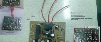
In conclusion, it should be noted that Western European leaders in this field are constantly patenting more and more new inductive sensors, references to which regularly appear in domestic abstract journals on electrical engineering. Innovations concern both circuitry and sensor design. In Russia, there are two or three electrical companies producing sensors that mainly use the first (generator) circuit. Their websites are listed at the end of the article. We recommend that the interested reader check out the website of the German company ifm electronic, one of the most successful in this area.
The article was first published in the journal “Devices and Systems. Management, control, diagnostics.” - Moscow, 2005. - No. 12. - pp. 36-39.
Bibliography:
- Sensors expo // Sensors. September 1990.
- Kolotov A. Contactless breaker of the electronic ignition system // Radio. 1993. No. 11.
- Gabov A.P., Ryzhov S.N. Inductive final sensor in an electric drive // All-Union Scientific and Technical. conf. “Tracking electric drives industrial. installations, robots and manipulators": Abstract. report Chelyabinsk, 1989.
If you have any questions about this material, you can ask them by emailing the co-author of the article