Purpose of electrical equipment of primary circuits
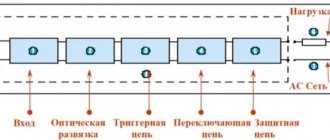
It is convenient to consider the purpose of devices and other elements of the switchgear in relation to the diagram of a specific installation (Fig. 1). As can be seen from the diagram, each connection has switches and corresponding disconnectors.
Switches
Q switches are the most important switching devices. They are designed to enable, disable and reconnect electrical connections. The switches must perform these operations in normal mode, as well as during short circuits (short circuits), when the current exceeds the normal value by tens and hundreds of times. The switches are equipped with drives for non-automatic and automatic control. A non-automatic operation of turning on or off is understood as an operation performed by a person who closes the control circuit of the switch drive with a special key, usually at a distance, i.e. remotely. Automatic switching on and off occurs without human intervention using automatic devices that close the same control circuits.
Switches are also provided in busbars.
These switches are called sectional QBs.
Diesel power plant connection diagram for the first special category of power supply
Another topic arose on the forum.
In this article I will consider in detail my simple solution for turning on/off a diesel power plant for an object of the first special category. According to the instructions, the input device (IDU) has one bus section, a working input, a backup input and a diesel power station. One section of tires makes things easier for us. Let's consider the diagram for connecting a diesel power plant with all devices and devices.
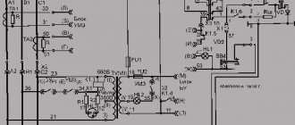
To turn on the diesel power plant in the presence of working and backup inputs, I propose the following scheme.
Diesel power plant connection diagram for the first special category of power supply
The scheme I proposed on the forum has some differences. When I began to select the necessary relays and check the functionality of the circuit, I noticed small errors that were easily fixed.
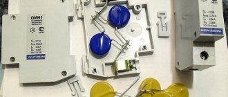
For each input we install a three-phase voltage relay of type CP-731, which includes make and break contacts. As protective circuit breakers 4QF and 5QF, you can take any modular three-phase circuit breaker with a rated current of 1A. 6QF is a single-phase machine with a rated current of 1A. Contactors KM1-KM3 must have additional contact attachments.
K1, K2 – intermediate relays of the REK type. In this scheme, I used them to multiply contacts.
HL1-HL3 – signal lamps. They signal through which input voltage is supplied to the ASU buses.
How does the diesel power plant switching circuit work?
There are 3 possible operation options for the circuit:
1 There is voltage at the working and reserve inputs (or only at the working input).
Relay KV1 includes an intermediate relay K1, which opens the circuit of the coils of the contactors KM2, KM3 and closes the circuit of the coil of the contactor KM1. Relay KV2 is disabled. Contactor KM1 turns on. The bus section receives voltage from the working input. Additional contacts of contactors KM1-KM3 prevent the simultaneous operation of three contactors.
2 There is no voltage at the working input (voltage is present at the backup input).
Relay KV1 turns off the intermediate relay K1, which closes (together with K2) the coil circuit of the contactor KM2 and opens the coil circuit of the contactor KM1. Contactor KM2 turns on. The bus section receives voltage from the backup input.
3 There is no voltage at the working and backup inputs.
The circuits of the power coils of contactors KM1 and KM2 are open. The remote start of the diesel power plant is triggered (contacts KV1.2 and KV2.2). The diesel power plant turns on, and then the coil of the KM3 contactor becomes energized and the bus section receives voltage from the diesel power plant. When voltage is restored at one of the inputs, the KM3 contactor is switched off and switched on as the base or backup input.
READ How to connect to iTunes Family
It is worth noting that the voltage relay CP-731 has a shutdown delay of 5 seconds. and allows you to set the restart time from 2 to 600 seconds. The operation of this circuit will be close to the operation of a modern automatic transfer switch, where it is possible to configure time delays for turning on and off.
This scheme is presented for the first time and has not been used anywhere. If you doubt the functionality of this circuit, install a ready-made AVR 3.0 unit. In general, before using the circuit, you should study the capabilities of a diesel power plant. In the upcoming issues I will tell you the nuances of connecting diesel power plants using my own example.
Source
DGS control panels
In switchgear stations, sectional switches are usually closed during normal operation. They should only open automatically in the event of a fault in the busbar area.
Together with them, other switches of the damaged section should also open. Thus, the damaged part of the switchgear will be turned off, and the rest will remain in operation.
If there is sufficient reserve in energy sources and lines, the power supply will not be disrupted.
Disconnectors
QS disconnectors have the main purpose of isolating (separating) electrical machines, transformers, lines, devices and other system elements from adjacent live parts during repairs for safety reasons. Disconnectors are capable of breaking an electrical circuit only when there is no current in it or at a very small current, for example, the magnetizing current of a small transformer or the capacitive current of a short line.
Unlike switches, disconnectors create a visible circuit break in the open position. As a rule, they are equipped with drives for manual control. Operations with disconnectors and switches must be carried out in a strictly defined order. When disconnecting a circuit, you must first open the breaker and then turn off the disconnectors, first making sure that the breaker is open. When switching on the circuit, operations with the switch and disconnectors must be performed in the reverse order. Thus, the switch closes and opens the circuit with current. Disconnectors form additional insulating gaps in a circuit previously disconnected by a switch.
Disconnectors are placed so that any device or any part of the switchgear can be isolated for safe access and repair. So, for example, in each linear circuit two disconnectors must be provided - busbar or linear, with the help of which the switches can be isolated from the busbars and from the network. In the generator circuit, it is enough to have only a bus disconnector, which ensures safe repair of the generator and circuit breaker; in this case, the generator must be turned off and stopped. To repair two-winding transformers and corresponding switches, it is enough to have bus disconnectors on the high and low voltage side.
Grounding devices
For safe work in switchgear and in the network, it is not enough to isolate the workplace from adjacent live parts. It is also necessary to ground the area of the system to be repaired. For this purpose, the disconnectors are equipped with grounding blades, with the help of which the area isolated for repair can be grounded on both sides, i.e. connected to the installation grounding device, the potential of which is close to zero. Grounding knives are equipped with separate drives. Normally grounding blades are disabled. They are turned on when preparing the workplace for repairs after turning off the switches and disconnectors and checking the absence of voltage.
The use of disconnectors is not limited to isolating disconnected parts of the system for safety reasons during repairs. In a switchgear with two busbar systems, disconnectors are also used to switch connections from one busbar system to another without breaking the current in the circuits.
Current-limiting reactors
Current-limiting reactors LR are inductive reactors designed to limit short-circuit current in the protected area. Depending on the location of switching on, linear and sectional reactors are distinguished.
Instrument current transformers
TA measuring current transformers are designed to convert current to values convenient for measurements. In connections of generators, power transformers, lines with complex types of protection, two or three sets of current transformers are required.
Voltage transformers
TV voltage transformers are designed to convert voltage to values convenient for measurements. Voltage transformers are connected to station busbars; they are also provided in connections of generators, transformers and lines.
Instrument transformers are usually not shown on circuit diagrams.
Valve arresters
Valve arresters F, as well as surge suppressors, are designed to protect the insulation of electrical equipment from atmospheric surges. They must be installed at transformers, as well as at the inputs of overhead lines into the switchgear.
Conductors
Current conductors are relatively short electrical lines (usually from several meters to several hundred meters) with rigid or flexible conductors mounted on support or suspension insulators, designed to connect electrical machines, transformers and electrical devices within a station, substation, switchgear .
Requirements for electrical equipment and conductors
The requirements for electrical equipment and conductors are as follows.
- The insulation of the equipment must have sufficient electrical strength to withstand the highest operating voltage, as well as switching and atmospheric overvoltages.
- Equipment and conductors must: carry the highest operating currents of the corresponding connections for an unlimited time; in this case, the temperature in the hottest points should not exceed the normalized values for continuous operation;
- withstand the thermal and mechanical effects of short-circuit currents, i.e. have sufficient thermal and electrodynamic resistance;
- be economical and reliable in operation, i.e. the likelihood of damage should be low, and the requirements for maintenance and repairs should be minimal;
- be safe for persons servicing the installation.
In addition to the listed general requirements, electrical equipment is subject to a number of specific requirements in accordance with the purpose and operating conditions of the equipment.
Electrical equipment ratings are parameters that determine the properties of electrical equipment, such as rated voltage, rated current, and many others.
Nominal parameters are assigned by manufacturers. They are indicated in catalogs, reference books, and on equipment labels. When designing an installation and selecting equipment, the ratings are compared with the corresponding design voltages and currents to ensure the suitability of the equipment for operation under normal and abnormal conditions. Here we will limit ourselves to just defining the concept of the rated voltage of the electrical network and electrical equipment.
The rated voltage is the base voltage of a standardized range of voltages that determines the level of insulation of the network and electrical equipment. Actual voltages at various points in the system may differ slightly from the nominal voltage, but they should not exceed the highest operating voltages established for continuous operation:
Rated phase-to-phase voltage, effective value, kV...
3..6..10..20..35..110
Maximum operating voltage, effective value, kV… 3.5..6.9..11.5..23..40.5
Rated phase-to-phase voltage. effective value, kV… 150..220..330..500..750..1150
Maximum operating voltage, effective value, kV… 172..252..363..525..787..1210
For networks with a rated voltage of 220 kV inclusive, the highest operating voltage is taken to be 1.15 rated; for networks with a rated voltage of 330 kV - 1.1 rated and for networks 500 kV and above - 1.05 rated. Electrical equipment must be designed to operate continuously at the specified voltages.
The insulation of electrical equipment must also withstand overvoltages, i.e. short-term exposure to voltages exceeding the highest operating voltage. There are switching and atmospheric overvoltages.
Secondary circuit devices. Relay protection and system automation elements
Automatic devices, in particular relay protection, are needed where a quick response to a change in operating mode and an immediate command to turn off or turn on the corresponding circuits are required. So, for example, during a short circuit, when the current in a number of circuits increases sharply, it is necessary to immediately turn off the damaged section of the system in order to reduce the size of the destruction and not interfere with the operation of adjacent undamaged circuits. Such a command can only be given by an automatic device that responds to changes in current, direction of power and other factors and closes the control circuits of the corresponding switches.
Automatic shutdown of system elements must be selective.
This means that in the event of damage at any cost, only the damaged circuit must be disconnected by the switches closest to the location of the damage. The rest of the system must not be disrupted. So, for example, when there is a short circuit at point K1 (Fig. 2), the current flows through the circuits of generators, step-up transformers, damaged and undamaged lines. However, only the damaged line on both sides must be disconnected. The station will remain connected to the system via another line.
In the event of damage to a generator or transformer, only the damaged element must be disconnected. In Fig. 2, areas of the system that must be disconnected in the event of damage are delimited by dotted lines. Each section is switched off by one or two switches. In the event of damage to the circuit breaker, two adjacent sections must be disconnected.
Fig.2. Electrical diagram of the station and network section. Dotted lines delimit sections of the station and network that are subject to disconnection in case of damage.
The selectivity of relay protection is ensured in various ways, for example, by appropriate selection of the time or current of operation of the protection of adjacent sections of the network, the use of relays that respond to the direction of power, etc.
The circuit shutdown time during a short circuit is composed of the relay protection response time and the circuit breaker shutdown time, calculated from the moment the shutdown command is given until the arc goes out at the breaker breaks.
They strive to reduce the shutdown time of the main lines of the system as much as possible so as not to disrupt the stability of the parallel operation of power plants. The shutdown time of the newest switches is two periods and the relay protection time is another 0.5 periods. The total shutdown time is therefore 2.5 periods. For distribution networks, 2.5-cycle tripping is not required. Here simpler protections and slower-acting switches are used, the cost of which is much lower. The total shutdown time is several tenths of a second or more.
Automatic restart
Automatic devices for re-closing (reclosure) of overhead lines after their protection has been disconnected are intended to quickly restore the operation of the line after a disconnection. The effectiveness of re-closing overhead lines is based on the fact that most short circuits are associated with lightning discharges and lead to overlapping of insulators along the surface. After the line is automatically turned off, the electrical strength of the air gap is quickly restored and when turned on again, the line remains in operation.
Initially, the command to restart was given manually by the person on duty at the control panel. Later, the switching operation began to be automated. Currently, automatic re-closing, single and double, is widely used. It helps to increase the reliability of power supply, especially when feeding consumers via single lines.
The total automatic re-closing time is calculated from the submission of the relay protection command to open the circuit breaker until the re-closure of its contacts. It should be as small as possible so as not to disrupt the work of consumers, but at the same time sufficient to deionize the arc gap at the point of overlap. The restart time depends on the mains voltage and the speed of the switch. In double-reclosing devices, the minimum time is selected for the first switching on from the condition of deionization of the arc gap. If the first switch-on is unsuccessful and the line is disconnected again, a second switch-on occurs with an interval of several seconds.
Automatic reserve input
Automatic devices for turning on a backup circuit (ATS) must automatically turn on a backup transformer or a backup unit to replace the one disabled by the protection, and also automatically connect the busbar section (with the corresponding load) that has lost power to an adjacent section provided with power, in order to quickly restore power supply. The break in the power supply should be relatively small, no more than 0.5 s, so that electric motors that have lost power do not have time to stop, and after power is restored they can quickly return to normal operation.
Automatic reserve input
If you are planning to buy a backup diesel generator (DGS) with automatic start in case of power outages in the main power grid - buy a diesel power plant - then be prepared that its price will be slightly higher than the standard configuration. The minimum that you will have to purchase additionally is a device for automatic recharging of starter batteries, an automatic electric engine heater, and most importantly, buy an automatic reserve input system
- or as it is also called - automatic load switching panel (ATS - automatic transfer switch, automatic transfer switch / ATS device, automatic transfer switch cabinet / ATS cabinet, automatic transfer switchboard for a generator / ATS switchboard, automatic transfer switch module / block ).
The price of an AVR is almost directly proportional to the maximum current strength (electrical power). Moreover, please note that the maximum current strength for the automatic transfer switch is determined not by the parameters of the reserve diesel power plant, but based on the rated current strength of the redundant network at the facility (load parameters).
By purchasing a backup diesel power plant, you will be provided with a fully automated backup source of electricity, which will restore electricity in 10-20 seconds
in your network (time to start the engine and reach the required power). If such a short interruption of power supply is unacceptable for you, then the supplied backup diesel generator with autostart can be integrated with an uninterruptible power supply of the required power.
An automatic transfer switch is required to automatically start a backup power plant and switch the load (consumer) to it in the event of a loss of current / deviation of current parameters in the main power grid
, as well as reverse automatic load switching and stopping of the backup diesel power plant when network parameters are restored. For this purpose, the power plant automatic transfer cabinet constantly monitors the parameters of the main electrical network.
The automatic transfer switch device - the ATS unit of Diesel Company's own design is carried out in a separate cabinet (ATS cabinet / ATS panel), which can be installed on the frame of a stationary backup diesel power plant, in a container or separately from the backup generator.
note
: when delivering an ATS for a generator in a casing, the ATS cabinet is placed outside the casing, the required length of power cables is determined by the Customer individually.
The AVR cabinet is installed as standard equipment on all backup diesel power plants with automatic start-up.
How does a power plant with automatic transfer of reserve work:
- The automatic transfer device, connected to the diesel power plant and the central power grid, continuously monitors the voltage and frequency of the current in each of the 3 phases of the main network.
The backup diesel power plant with automatic transfer switch is automatically maintained in a state of constant readiness: in the cold season, the coolant is systematically heated, and the starter batteries are automatically recharged. - When the current disappears in the main power grid
or when the frequency/voltage of the current deviates by a given amount,
the ATS system automatically starts the backup diesel power plant
. - When the current parameters in the main network are restored within a programmable period of time (network stabilization), the consumer's power supply is automatically switched back
from the backup power source to the main network. - The ATS has electrical and mechanical protection (blocking)
, which prevents simultaneous back-to-back connections of the main and backup power sources.
The Diesel company produces 2 types of automatic transfer switches for diesel generators:
- ATS based on contactors:
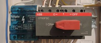
the most common type of automatic transfer device for a diesel generator. The principle of its operation is the mutual electrical and mechanical interlocking of contactors when switching the phase control relay. - ATS based on motor-driven automatic switches.
The basis of such an ATS module for diesel power plants is a switch - a switch with a zero middle position, driven by a motor drive. The drive is controlled by a controller, which is part of the automatic switch. The ATS device for diesel power plants based on a switch with a motor drive has the greatest reliability.
Diesel Company specialists will select for you the optimal configuration of a backup diesel power plant - with the optimal price and maximum efficiency. If necessary, we will create an integrated system from an uninterruptible power supply and a “catch-up” backup generator. By purchasing a diesel generator set with an automatic transfer device from us, you are purchasing a reliable, autonomous source of power supply for your facility, which will definitely not let you down - it will insure your electrical equipment for many years after purchase.