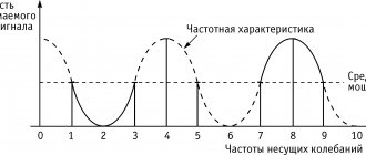
Types of sound switches
Acoustic switches can respond to voice commands and claps.
The following types of acoustic switches exist:
- Devices that react to cotton. It is programmed in advance at what number of claps a particular command will be executed.
- Devices that respond to voice or a preset command.
- Combined devices (for example, light-acoustic switch). They can be equipped with sound, light or motion sensors. These are the most technologically advanced devices in which the risk of false alarms is minimized.
- Devices for low-current systems. Used to connect a video camera or transmit a command to security.
Acoustic switches have become popular due to their ease of use. They are useful for the elderly, bedridden patients and young children. Devices of this class are already actively used in the Smart Home system.
Advantages
Excellent switching properties, closed design, simplicity and reliability of design solutions allow the switches to be used as part of a wide range of equipment operating in various conditions.
Vacuum circuit breakers are designed for operation in KSO and switchgear cabinets, including KRUV indoor and outdoor installations for voltage class (kV) of three-phase alternating current for systems with an isolated neutral.
Vacuum circuit breakers are operated in normal climatic conditions (UZ climatic version according to GOST 15150-69, groups M6, M7), namely:
- the upper operating and effective value of the ambient air temperature, taking into account the temperature rise in the switchgear, is +40 °C;
- the maximum lower operating value of the ambient air temperature is -40 °C;
- highest altitude above sea level - 4,500 m.
When operating cameras at an altitude of 1,000 m or more, the requirements for electrical insulation strength and rated current must be reduced by values corresponding to the altitude corrections in accordance with GOST 1516.1-76 and GOST 15150-69. The content of corrosive agents in the ambient air is for atmosphere type II (industrial) according to GOST 15150-69. Relative air humidity (average annual value) - 75% at 15 °C; dust content in the ambient air up to 10 mg/m; the environment is non-explosive.
Vacuum switches are resistant to mechanical external influences in accordance with GOST 17516.1-69 under vibration loads in the frequency range from 1 to 35 Hz for severity level I, single impacts with acceleration up to 3g lasting from 2 to 20 ms.
Vacuum switches ensure normal operation and standardized parameters during roll and trim in any position.
A vacuum arc suppression chamber (VAC) is used to extinguish an alternating current arc when opening contacts in a deep vacuum (residual pressure of the order of 10-6 mm Hg). The charge carriers during arc combustion are metal vapors. Due to the virtual absence of a medium in the intercontact gap, condensation of metal vapor at the moment the current passes through natural zero occurs in an extremely short time (10-5 s), after which the electrical strength of the VDC is quickly restored. The electrical strength of the vacuum is about 30 kV/mm, which guarantees that the current will be switched off when the contacts diverge more than 1 mm.
The switch uses a modern VDK design with an enhanced axial-radial magnetic field. The arc in such a field is always in a diffusion state, which significantly reduces wear, which does not exceed 1 mm after the switching resource is exhausted.
Compression SF6 circuit breakers
Let's consider the principle of operation of an auto-compression SF6 gas switch. The main components of this switch are shown in (Fig. 5.). Rice. 5. Auto-compression SF6 gas circuit breaker Upper current input SF6 gas absolute pressure 0.5 bar. Sealing cap Fixed arc-extinguishing contact Movable main contact Connections between moving and stationary parts Movable arc-extinguishing contact Pressure chamber Piston Valve Spring Lower current input Main rod made of insulating material Shaft lever Seal system Shaft Molecular sieve Mounting point When switched on, current flows through the upper current input (1 ), fixed arc extinguishing contact (4), movable main contact (5) and lower current input (12) (Fig. 6, a). After the shutdown command, the drive activates the shaft (16), which, rotating, through the sealing system (15) transmits mechanical torque to the main rod (13) through the lever of the shaft (14) and the SF6 gas is compressed in the pressure chamber (8) (Fig. 6, b). In this case, the fixed and movable arc extinguishing contacts (4 and 7) remain closed due to the preload of the spring (11). After this, the fixed and movable arc extinguishing contacts (4 and 7) begin to diverge due to the weakening of the spring (11) (Fig. 6c). The main rod of insulating material (13) begins to move them away from each other. When the fixed and movable arc extinguishing contacts diverge, an arc begins to burn between them. As can be seen in Fig. 5. A piston (9) with a sealing nozzle (3) is attached to the movable arc-extinguishing contact, moving in the pressure chamber (8), while simultaneously providing cooling and blowing out the arc with SF6 gas under high pressure. A pressure chamber with a piston and a sealing nozzle with full divergence of the contacts ensures complete extinction in the arc-extinguishing chamber (Fig. 6d). A more advanced and reliable model of the auto-compression switch is the auto-compression switch with main current-carrying contacts. Let's consider its principle of operation and determine its components: When turned on, current flows through the main conductor, consisting of the upper and lower current input (22 and 19) and from the fixed and moving contact of the main conductor (20 and 21). After the shutdown command, the drive activates the shaft (14), which, rotating, through the sealing system (13), mechanically transmits torque to the connecting rod (17), attached to the main rod (10). The main rod pulls down the moving contact of the main conductor and the main conductor breaks. In this case, the stationary and movable arc extinguishing contacts (4 and 6) remain closed due to spring preload (9) and the disconnected current is redistributed from the main current conductor to the arc extinguishing current conductor, connected to the lower current input (19) through the main rod (10) and a flexible busbar ( 18).
Rice. 6. Operating principle of an auto-compression switch Cover Sealing shell Pole device Fixed arc-extinguishing contact Sealing nozzle Movable arc-extinguishing contact Piston Pressure chamber Spring Main rod Pole device Curved handle Sealing system Shaft Molecular sieve Cover Connecting rod Flexible bus Lower current input Movable contact of the main conductor (inclined blade contact) Fixed contact of the main conductor Upper current input Fig. 7. Auto-compression SF6 circuit breaker with main current-carrying contacts
Closed circuit breaker Open main contact Arcing period Open circuit breaker Fig. 8. Operating principle of an auto-compression circuit breaker with main current-carrying contacts After the redistribution of the current from the main current-carrying conductor to the arc-extinguishing current-carrying conductor, the fixed and movable arc-extinguishing contacts (4 and 6) begin to diverge; due to the weakening of the spring (9), the main rod begins to move them further and further away from each other friend. When the fixed and movable arc extinguishing contacts diverge, an arc begins to burn between them. As can be seen in Fig. 7. A piston (7) with a sealing nozzle (5) is attached to the movable arc extinguishing contact, moving in the pressure chamber (8), while simultaneously providing cooling and blowing out the arc plasma with SF6 gas under high pressure. A pressure chamber with a piston and a sealing nozzle with full divergence of contacts ensures complete extinguishing in the arc-extinguishing chamber. The described process is depicted in Fig. 8.
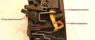
Design and operation of circuit breaker components
Vacuum switch VVR-10-20/630 Click on the picture to enlarge
The VVR-10-20/630 switch consists of the main parts:
- The switch pole, which in turn consists of: an insulating frame;
- vacuum arc-extinguishing chamber (VAC);
- upper current output;
- lower current output and flexible connection with the moving contact of the VDK;
- insulating rod with a VDK contact prestressing unit mechanism,
- radiators (if necessary);
The mechanism of the contact prestressing unit serves to compensate for the wear of the KDV contacts that occurs during switching of load currents and short-circuit currents, as well as to ensure normal operation of the switch in the “B” and “BO” cycles during switching. KDV is a non-repairable product and does not require maintenance during its entire service life.
In the process of turning on the switch, after closing the contacts of the KDV, with further rotation of the switch shaft, the spring of the preloading unit mechanism is preloaded and a “pressure” of the contacts is created, amounting to 900-1100N.
The spring drive consists of:
- drive shaft with engagement latch mechanisms and cam;
- an intermediate shaft with a trip latching mechanism and a rod connecting the drive and the switch shaft;
- on and off electromagnets
- activation springs;
- on and off buttons;
- drive block contacts;
In addition, during assembly, a manual winding shaft of the activation spring with a spring position indicator is installed on the drive, and the gear motor shaft is attached.
The signaling unit is designed to ensure the operation of the circuit breaker control circuit. Its free block contacts are intended for use in circuit breaker protection and signaling circuits. The signaling unit consists of 8 normally open and 8 normally closed contacts connected to the switch shaft with a pin. The moment of operation of the block contacts of the alarm unit is determined by adjusting the switch in the “off” position.
The indicator lever is equipped with signs “B” and “O”, indicating the position of the switch.
Types of vacuum circuit breakers
- vacuum circuit breakers up to 35 kV;
- vacuum circuit breakers above 35 kV;
- vacuum load switches - a modern replacement for autogas load switches;
- Vacuum contactors up to and above 1000 V.
Advantages
- simplicity of design;
- ease of repair - if the camera fails, it is replaced as a single unit;
- the ability to operate the switch in any position in space;
- reliability;
- high switching wear resistance;
- small sizes;
- fire and explosion safety;
- absence of noise during operations;
- no environmental pollution;
- ease of use;
- low operating costs.
Flaws
- relatively small rated currents and shutdown currents;
- the possibility of switching overvoltages when switching off small inductive currents - the modern development of a vacuum circuit breaker with the possibility of synchronous switching solves this problem;
- short resource of the arc extinguishing device for disconnecting short circuit currents.
The switching device is switched on and off using the corresponding springs. The springs are activated by the action of special on and off electromagnets (solenoids), or by pressing the on and off buttons directly in the explosive drive.
Before turning on the switch, it is necessary to bring the switching spring into working position, that is, cock it. The spring is charged when operating current is supplied to the electric motor of the explosive drive. If it is not possible to supply operating current, for example, when the DC switchboard is de-energized, the spring can be charged manually using a special handle.
So, to turn on the switch remotely, an operating current (usually constant) is supplied to the on solenoid through the control key. To control the switch from the spot, press the power button. In both cases, the closing latch is acted upon, which releases the closing spring, which turns on the vacuum circuit breaker.
. This will activate the release spring. The electrical circuit of the drive is designed in such a way that after turning on the device, the activation spring is automatically charged.
Electrical diagrams and basic operation of switches
Purpose of the control circuit:
- prompt switching on and off;
- blocking against repetition of closing and opening operations of the circuit breaker when the closing command remains given after automatic tripping;
- signaling of the switch position using switching contacts for external auxiliary circuits and control circuits.
Description of the circuit operation
Preparing the circuit for inclusion
To prepare the circuit for switching on, an alternating operating voltage or a constant (rectified) voltage is supplied to terminals XT:26 and XT:27 (circuits of the gearmotor circuit for winding the activation spring). The gear motor charges the activation spring. After the cocking is completed, the drive position block contacts SQM1,2 are activated, opening the power supply circuit of the gearmotor.
Also, in this case, the KV1 drive position signal repetition relay is activated along the circuit: terminal XT:26, drive position block contact SQM1-2, diode bridge VD4, blocking relay winding KBS, drive position block contact SQM2-2, terminal XT:27. The relay with its contacts KV1-3 prepares the switching circuit, with its contacts KV1-2 it prepares the external control circuits (RCC), with its contacts KV1-1 it breaks the blocking circuits from restarting.
We advise you to study How to test a resistor with a multimeter
Vacuum switch VVR-10-20/630 Click on the picture to enlarge
Turning on the switch
To turn on, an alternating operating voltage or a constant (rectified) voltage is supplied to contacts XT:23 and XT:25, while the supply voltage through the rectifier on the diode bridge VD1 is supplied to the coil of the switching electromagnet YAC through the circuit: XT:23, n.c. KBS blocking relay contacts, n.o. contacts of the actuator position signal repetition relay KV1.3, NC switch position contacts Q6.1, diode bridge VD1, self-restoring fuse FU1, contact XT:25.
The YAC closing electromagnet is activated and the switch is turned on. When switched on, the block contacts of the switch Q1…Q10 are also activated. Block contacts Q7.1, Q8.1 prepare the trip command.
Trip the circuit breaker
To turn off, an alternating operating voltage or a constant (rectified) voltage is supplied to the contacts XT:28 and XT:29, while the supply voltage through the rectifier on the diode bridge VD5 is supplied to the coil of the switching electromagnet YAT through the circuit: XT:28, n.c. switch position contacts Q8.2, diode bridge VD5, self-restoring fuse FU3, contact XT:29.
The YAT trip electromagnet operates and the circuit breaker opens.
The switch can also be switched off from current electromagnets YAA1 and YAA2 for circuits with de-shunting or a YAV shutdown electromagnet of an independent power source.
To turn off the switch, capacitor C3 installed in the switch circuit can be used. Capacitor C3 is charged after voltage is applied to contacts 26 and 27 of the switch terminal block. To turn off the switch, it is necessary to connect contact XT:32 with contact XT:28 of the terminal block using external control circuits (in this case, contacts XT:26 AND XT:29 must be combined into a common circuit). The switch will turn off via circuit (+) C3, self-resetting fuse FU2, ХТ:32, ХТ:29, Q7.1, Q8.1, VD5, YAT, ХТ:27(ХТ:29). To disconnect from the capacitor, you can use other electromagnets installed in the switch circuit (except current ones).
Design features
Design of a vacuum switch
Each model of a high-voltage vacuum switch has individual characteristics, since it is intended for operation in networks with different electrical parameters. In addition, manufacturers also make some adjustments to the design of the products they produce. However, in general, the composition of the components of these devices remains unchanged. Essential elements:
- A housing made of durable metal, inside which an on/off drive is mounted (may be spring or another type).
- A 3-pole current collector designed for connection to a 380 Volt network and disconnected when the switchgear is transferred from the operating mode to the pumped-out position.
- A trolley for placement inside the housing, differing in its design from other similar structures.
The electrical part of the product has special partitions that separate the phase sections from one another. It also has a complex structure and contains a number of elements described in the passport.
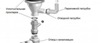
Thermostatic steam traps (capsule)
The operating principle of a thermostatic steam trap is based on the temperature difference between steam and condensate.
The working element of a thermostatic steam trap is a capsule with a seat located in the lower part, which acts as a locking mechanism. The capsule is fixed in the body of the steam trap, with the disk located directly above the seat, at the outlet of the steam trap. When cold, there is a gap between the capsule disk and the seat, allowing condensate, air and other non-condensable gases to freely exit the trap.
When heated, the special composition in the capsule expands, affecting the disk, which, when expanded, falls onto the seat, preventing steam from escaping. This type of condensate traps, in addition to removing condensate, also allows you to remove air and gases from the system, that is, to be used as an air vent for steam systems. There are three modifications of thermostatic capsules that allow condensate to be removed at temperatures 5°C, 10°C or 30°C below the vaporization temperature.
Main models of thermostatic steam traps: TH13A, TH21, TH32Y, TSS22, TSW22, TH35/2, TH36, TSS6, TSS7.
SF6 circuit breakers operating principle
The method of extinguishing an arc using various gas mixtures has long been known both in scientific physics and in the production process.
Modern equipment containing prepared gas is widely used for production purposes to prevent emergency situations.
But not everyone knows exactly what processes are occurring in the device itself at this moment. Therefore, below we will consider the principles on which such a device as a SF6 gas switch is based.
Design Features
An SF6 circuit breaker is a device designed to control and supervise high-voltage electrical networks. In terms of its design principles, it is close to an oil switch, but instead of an oil mixture there is gas inside. Also, such a comparison shows that the SF6 apparatus is much more durable and requires less maintenance.
Typically, sulfur is used as a gas, but other mixtures also exist.
The following types of design exist:
This device is also classified based on the extinction method:
- rotating;
- air;
- longitudinal.
Operating principle and scope of application
The operation of the device is based on phase isolation using SF6 gas.
In detail, the operating principle of the column switch is as follows:
- The arrival of the shutdown signal causes the camera signals to open.
- After this, the built-in contacts of the device create an arc.
- The activated arc environment causes the gas to actively split into particles.
- The high pressure caused by this process reduces the very high-quality conductivity of the medium and the arc goes out.
Some designs provide a separate compressor, which helps to escalate the situation in devices operating at low pressure. Also, during gas blasting, shunting is used, due to which the current strength is equalized and the process is stabilized.
The operating principles of core devices are somewhat different:
- The device is controlled by transformers and additional drives. This approach provides the ability to hold the arc within a certain power, as well as controlled switching off and on of the entire network;
- The drives themselves are hydraulic and spring. Purely spring mechanisms are completely built on mechanical joints, therefore they are structurally simple and reliable. Hydraulic drives are a hydraulically enhanced version of a spring mechanism.
The hydraulic system is more reliable due to hydraulic insurance, but at the same time it is burdened with the risks associated with it.
Advantages and disadvantages
Any mechanism or device has a number of advantages and disadvantages.
We advise you to study All about fuses
In our case, the first include:
- Multifunctionality - there are simply no voltages that the device cannot handle.
- Speed – the reaction speed of SF6 gas is measured in thousandths of a second, which allows emergency shutdown to occur in a really short time.
- Fire safety and vibration resistance.
- Service life - the device body is reliably protected, and the contacts protected by the gas environment are not subject to wear in principle.
- Operability in high voltage networks - vacuum devices cannot do this.
This is where the best features of such a switch end, so let’s move on to the disadvantages:
- Price - the SF6 gas mixture itself is expensive, and the work to create the device is quite expensive, which is why this switch is quite expensive.
- Low temperatures are the biggest disadvantage of this device. The device, in principle, is not capable of operating at low temperatures, because they greatly affect the physical properties of the contents, disrupting the performance of the entire system.
- Expensive maintenance – repair work for devices of this type is quite rare. Its design features help it remain reliable almost always, but if repairs are necessary, they will be very expensive. Firstly, such repairs can only be carried out using high-precision equipment, which in itself is rare, and secondly, specialists who know how to handle this equipment also ask for high fees.
- Expensive installation - the situation is completely similar to maintenance. Installation is extremely difficult to perform, so work on preparing a special platform can only be carried out by a professional.
You can learn more about the device and operating principle of the SF6 gas switch in the video below:
Finally
We hope that now there are no gaps left for you in the theoretical principles of operation of SF6 high-voltage circuit breakers.
What types of vacuum circuit breakers are there?
All vacuum circuit breakers are divided into two large groups: circuit breakers for voltages up to 35 kV and devices for voltages above 35 kV.
Three poles are attached to the frame of the first type. In this case, on each of them there is an arc-extinguishing chamber, as well as a joint prestressing unit. In addition, an electromagnetic drive is installed on the frame. This drive is used to control the arc extinguishing vacuum chamber.
The device, designed for voltages above 35 kV, already has several cameras on each frame. If there are two of them, then they are located opposite each other. They are controlled through insulating traction. If there are three cameras, they are installed in a row one after another. In this case, they are controlled by a hydraulic system.
Vacuum switches of the VVE-10 type are intended for power lines where there is a voltage of 10 kV, with a frequency of 50-6 Hz, with a rated current of 630-3200A. At the same time, the strength of the switched shock currents is from 52 to 82 kA, and the power of the switched shock currents is from 20 to 31.5 kA.
Based on this device, arc extinguishing chambers of two poles with electrical connections and an electromagnetic drive are manufactured, which controls the operation functions of this device. The front panel contains additional devices that regulate the control and alarm system.
Vacuum devices type BB/TEL-10-8/800U2. Used in electrical circuits with a voltage of up to 20 kV of three-phase alternating current, corresponding to a value of 50 Hz and a grounded zero. The rated current of this switch is 8kA.
Due to its design features, the switch has a number of advantages:
- when operating from the network, it consumes a small amount of energy;
- equipped with a tele-alarm function;
- reliable in operation;
- does not require repairs during its service life, which is 25 years;
- installed in any electrical cabinets of various modifications;
- safe to use for the environment.
Features of application and operation
Introduction to Oil Switch
Vacuum circuit breakers were initially developed structurally as a device used only in switchgear cabinets (complete switchgear). Currently, they are also used for open distribution devices (OSD).
A modern high-voltage vacuum circuit breaker is a new generation of high-speed switching devices designed for a longer service life than its predecessors with oil or SF6 gas media for extinguishing an electric arc. Statistically, the percentage of their use in electrical installations above 1000 Volts is growing steadily. Chinese power engineers have already completely abandoned outdated oil valves and have completely switched to vacuum switches that are more compact and do not require frequent maintenance. The vacuum switch is quite unpretentious and does not require regular cleaning of contacts and changing oil, which often flows quite abundantly from the tanks. According to the passport data, the service life of vacuum circuit breakers is about 20 years.
During operation, the drive mechanism may fail, and it is necessary to supply power to a certain important mechanism in the production chain, therefore all switches must be equipped with a manual spring charging mechanism. It is also mandatory to have an emergency button to disable the rolling out locking mechanisms when it is on. This is the safety of personnel, so this point is very important.
Compatibility with other units
The autonomy of a smart switch depends on design nuances. Devices with a Wi-Fi signal receiver are controlled directly from the phone without additional devices. Analogs with Z-Wave or Zig-Bee systems require an additional controller that acts as an intermediary between the smartphone and the switch. An identical device is also used to store preset programs. For example, the range of automatic switching off and switching on of lamps.
Innovative technologies make it possible to install an interacting system that includes several smart devices. The user can configure the switch in several modes, including triggering the device when the doors are opened based on a sensor signal. The level of luminous flux, in turn, can affect the operation of other household devices, such as an air conditioner or humidifier.
Pros and cons of using
Vacuum circuit breakers are gradually replacing oil or SF6 devices from the market. This is explained by the advantages that they have over other switches:
- simple installation of vacuum devices in place of outdated oil-filled ones;
- ease of repair and maintenance;
- increased service life;
- small overall dimensions and weight;
- reduced risk of device fire;
- seismic resistance and general vibration resistance;
- good environmental characteristics.
Vacuum circuit breakers also have disadvantages. There are comparatively fewer of them:
- poor resistance to short-circuit currents;
- increased cost of the device;
- risk of overvoltage during shutdown;
- The device does not turn on without a standby power source.
Additional Information. The disadvantages of oil-filled switches include increased risk of explosion. When arc processes develop in them, the oil actively releases flammable vapors. If the arc-extinguishing chambers are insufficiently filled, an explosion may occur. Thus, a vacuum device is an order of magnitude safer than an oil device.
Advantages and disadvantages of vacuum circuit breakers
- Small dimensions compared to oil and air circuit breakers.
- Possibility of quick replacement, especially in withdrawable cells.
- Relatively low noise level.
- Environmentally friendly.
- They do not require periodic compensation of the working environment level, reducing the amount of maintenance work to a minimum.
- High reliability.
- The occurrence of overvoltage when cutting off small inductive currents.
- Small switching resource for switching off emergency currents.
Application of vacuum circuit breakers
Vacuum switches used in the energy sector are high-voltage switching devices that perform operations to turn on and off electric current. These actions with electric current are carried out both in working condition and in an emergency situation, when a short circuit occurs. The medium that extinguishes the electric arc is vacuum.
Currently, the number of vacuum circuit breakers used in electrical networks with voltages up to 35 kilovolts in different countries ranges from 60 to 100% of the total number of switching devices used at medium and high voltage.
Characteristics of vacuum circuit breakers
- Home →
- Articles →
The main purpose of vacuum circuit breakers is to operate in switchgear compartments in three-phase current-carrying circuits with an oscillation frequency of 50 Hz and a separate or replaced neutral; in addition, they are designed for industrial cabinets, where they act as controlling links for incoming electricity. They do an excellent job of switching, opening and closing main cables without damaging the control contacts.
In accordance with the characteristics of vacuum switches, their use is allowed to start and interrupt the operation of asynchronous type motors with a short-circuited or phase-type rotor. They do an excellent job of slowing down the torque of countercurrent motors and stopping the operation of electric machines with a slowly rotating rotor.
The duration of operation of the circuit breaker before the first major overhaul is on average 12 years; it is recommended to write off the used mechanism no later than after a quarter of a century.
An important feature of vacuum circuit breakers is the ability to operate continuously with frequent switching operations. Switches with a drive operating through the interaction of an electromagnet and a ferromagnet are capable of switching electrical circuits in standard and emergency modes in three-phase current-carrying circuits with an oscillation frequency of 50-60 Hz, where there is an isolated neutral and the standard voltage does not exceed 12 kV.
Thanks to the existing characteristics of vacuum circuit breakers, they can be called ideal from an environmental point of view. They are practically safe for the environment and do not produce harmful emissions into the atmosphere during operation. Absolute tightness increases reliability and the number of possible switching operations throughout the entire service life. The lowest temperature limit is -60ͦС. The presented equipment can operate in both automatic and manual mode. Based on the presented parameters, vacuum circuit breakers are able to fully function even in difficult climatic conditions. The device for unhindered disconnection of the drive is capable of stopping the operation of the circuit breaker at any moment, despite the position of the mechanism. In addition, due to their small size and weight, as well as fire and explosion safety, they can be installed near an aggressive environment.
Vacuum type circuit breakers are designed for use in substations designed for 110 -220 kV with current and voltage transformers that do not contain oil and SF6 gas. It is especially important to operate such substations in areas with strict environmental restrictions on industrial equipment.
Modernized developments in the production of vacuum circuit breakers are designed for a long period of time, so a constantly updated element base allows us to improve switchgear for high-voltage circuits and design the latest block-modular power supply systems for consumers.
Properties of SF6 gas.
SF6 gas (electrical gas) is sulfur hexafluoride SF6. At operating pressures and normal temperatures, SF6 gas is colorless, odorless, non-flammable, and 5 times heavier than air. SF6 gas does not age, that is, it does not change its properties over time; it disintegrates during an electrical discharge, but quickly recombines, restoring its original dielectric strength. At temperatures up to 1000 K, SF6 gas is inert and heat-resistant; up to temperatures of about 500 K, it is not chemically active and is not aggressive towards metals, casting resins and rubbers. SF6 gas is an “electronegative” gas. Its molecules in an electric field have the ability to capture electrons, forming sedentary, heavy negative ions. Due to this, SF6 gas has high electrical strength. At a pressure of 0.23 MPa, the discharge voltage in the SF6 gas is equal to the discharge voltage of the transformer oil. In SF6 gas at atmospheric pressure, an arc can be extinguished with a current several times higher than the current switched off in air at the same pressure; SF6 molecules trap the electrons of the arc column; the loss of electrons makes the arc unstable and easily extinguishes. In a stream of SF6 gas, i.e., during gas blast, electrons from the arc column are absorbed even more intensely. The performance of SF6 gas improves in a uniform field, so the design of the individual elements of the switch must ensure the greatest uniformity and homogeneity of the electric field. In a non-uniform field, local overvoltages of the electric field appear, which cause corona discharges. Under the influence of these discharges, SF6 gas decomposes, forming lower fluorides, which have an adverse effect on the structural materials used in the arc extinguishing device. To avoid discharges, the surfaces of metal screens leveling the field must be clean, smooth, and free of burrs. Dirt, dust, and metal particles on the surface of the screens create local field inhomogeneity, which worsens the electrical strength of SF6 insulation. The high dielectric strength of SF6 gas provides a high degree of insulation with minimal dimensions and distances, and reliable arc extinction and coolability of SF6 gas increase the breaking capacity of switches and reduce heating of live parts. The use of SF6 gas allows, other things being equal, to increase the current load by 25%. The disadvantage of SF6 gas is its transition to a liquid state at relatively high temperatures (-40°C), which determines additional requirements for the temperature regime of SF6 gas equipment in operation, for example, the tank of a SF6 gas circuit breaker is heated to +12C.
We advise you to study Measuring the resistance of a grounding device
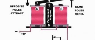
Operating principle
The arc extinguishing mechanism in vacuum circuit breakers is based on the high electrical strength and enhanced dielectric properties of vacuum. At the moment the contacts open, an electric arc occurs in the vacuum gap, which is maintained by the metal evaporating from the surface of the contacts. When the current passes through zero, the arc is extinguished and the dielectric properties of the vacuum gap are restored, and the arc no longer occurs between the open contacts. Due to the high electrical strength of the vacuum, arc extinguishing can occur before the current crosses zero; this phenomenon is called current cutoff. Current cutting negatively affects the network, as it causes switching overvoltages, which can reach enormous values.
Disadvantages of vacuum circuit breakers
1. Difficulties in development and manufacturing associated with the creation of special contact materials, the complexity of vacuum production, and the tendency of contact materials to be welded under vacuum conditions.
2. Large capital investments required to set up mass production.
In mass production, the cost of vacuum switches is only 5-15% more than the cost of low-oil ones and less than the cost of electromagnetic ones. Great savings in operation make these switches highly efficient, which makes them increasingly widespread.
Device and principle of operation
Vacuum circuit breakers are designed to perform switching operations in high voltage power supply networks. Structurally, a vacuum circuit breaker consists of three separate poles or columns (one for each phase). All speakers are installed on one drive using a support insulator made of polymer, porcelain or textolite. Each of them has two terminals for connecting a busbar.
General view of a vacuum circuit breaker
Vacuum circuit breaker device.
From the picture below you can see that inside the device consists of two contacts connected to the corresponding pole potentials. One of them is movable, the second is stationary, as in other types of switches. The power contacts of the vacuum switch are located inside a sealed chamber capable of maintaining a vacuum for a long period of time (several decades). Why are special metal alloys and ceramic additives included in the chamber? It was this element that became a stumbling block for the implementation of such a switch in the 30s of the last century.
Modern technologies make it possible to maintain a vacuum inside the container, including taking into account the dynamic loads that it has to endure during switching. To constantly maintain the state of a highly rarefied gas environment inside the vacuum chamber, the device is equipped with a bellows component. It eliminates the possibility of air or other gas entering the vacuum chamber when the moving contact moves.
Vacuum circuit breaker design
The principle of extinguishing an electric arc.
When contacts between surfaces are broken, space ionization occurs. If in air circuit breakers using the electromagnetic blast method this ionization is artificially extended by several meters, and in SF6 and oil circuit breakers they try to extinguish it with dielectric material, then in vacuum circuit breakers a different technology is used. The basic principle is based on the fact that in an ideal vacuum there is no substance capable of releasing charged particles. Therefore, at the moment of separation of the contacts, due to the potential difference, the only source of ionization is vapor of hot metal.
They continue to move between the contact surfaces, but when the electric current sinusoid passes through zero, the charged particles lose energy for ionization and movement, their place is quickly taken by empty space with high electrical strength and the arc breaks. Metal ions are adjacent to the nearest surface - contacts or chamber walls. This principle of operation allows you to reduce the time to stop the arc burning and provides a number of advantages in comparison with other types of switching devices. But excessive switching overvoltages can lead to surface deformation, which will prevent normal contact closure, increase contact resistance and cause overheating inside the vacuum chamber.
General structure and principle of operation of air switches
Main article: Air circuit breaker
In air circuit breakers (AC), the energy of compressed air is used both as a driving force that moves contacts and as an arc extinguishing medium. The principle of operation of an arc extinguishing device (AD) is that the arc formed between the contacts is subjected to intensive cooling by a stream of compressed air flowing into the atmosphere. When the current passes through zero, the arc temperature drops and the gap resistance increases. At the same time, mechanical destruction of the arc column and removal of charged particles from the gap occurs.
Explosives are structurally divided into:
- Switch with open separator
- Circuit breaker with gas separator
- Switch with chambers in a compressed air tank
Features of choice
In order to correctly select this type of high-voltage switches, in accordance with local operating conditions and specific equipment, you should pay attention to the following criteria:
- Rated voltage;
- Dynamic stability;
- Control system parameters;
- Rated current in operating mode and short circuit mode;
- Frequency of switching on and off;
- Climatic performance;
- Switch operation speed;
- The frequency of preventative repairs and inspections is a very important aspect in electrical installations without local duty personnel;
- Wear resistance against short circuits;
- Dimensions and size of the vacuum installation.
Types of Vacuum Circuit Breakers
Like any other electrical products, vacuum switches are divided into several types, depending on the voltage class for which the device is intended. Therefore, they can be conditionally divided into:
- Devices for 6 – 10 kV;
- 35 kV devices;
- Devices for 110 – 220 kV.
The second criterion is the power of the disconnected consumer, according to which models differ in maximum operating current or power.
Literature
- Amethystov E.I.
Fundamentals of modern energy under the general editorship of corresponding member. RAS E.V. Ametistova - M.: MPEI Publishing House, 2004.- 822 p. - Neklepaev B.N.
Electrical part of power plants and substations / B.N. Neklepaev, I.P. Kryuchkov - M.: Energoatomizdat, 1989. - 605 p. - Poltev A.I.
Designs and calculations of gas-insulated high-voltage devices. - L.: Energy, 1979. -240 p.; - High voltage electrical devices / Edited by G. N. Aleksandrov. - L.: Energoatomizdat, 1989. - 344 p.;
- Handbook of high-voltage electrical apparatus/ Edited by V. V. Afanasyev. - L.: Energoatomizdat, 1987. - 544 p.;