When working in electrical installations, it is important to monitor the condition of circuits and live parts. The initial check (for safety purposes) reveals the presence or absence of voltage in the work area. For this, a voltage presence indicator is used, which is manually connected by the operator, that is, it is not an element of the electrical installation design.
In what cases is it necessary to use a voltage indicator:
- before starting repair work in an electrical installation;
- before applying portable grounding;
- to determine the area where the accident occurred;
- to identify conductive parts of an electrical installation that should not have dangerous potential.
Important: Safety, and even the life of an electrician, depends on the correct use of the voltage indicator!
We will look at the principle of operation of high voltage indicators, types and methods of their use.
Division by type
- By voltage, voltage indicators are divided into up to 1000 V and over 1000 V. For domestic use, low-voltage devices up to 1 kV are usually used. However, these are all high voltage indicators. According to the standards of the PUE (Electrical Installation Rules), AC voltage up to 50 V and DC voltage up to 120 V are safe for humans. Under unfavorable conditions (humidity, conductive dust), AC voltage up to 25 V and DC voltage up to 60 are considered high. B. Voltage indicators above 1000 V are used by professional electricians; for household electrical networks of 220 V and 380 V their use is impractical. For example, UVNU-10 with an external rod.
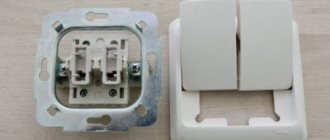
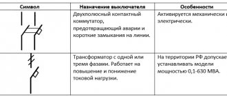
- According to their design, voltage indicators up to 1000 V are divided into single-pole and double-pole. The first option is an indicator screwdriver rather than a tool. The second option is preferable when it comes to accuracy and guaranteed determination of dangerous potential.
- By type of electric current: AC or DC. In domestic applications, the high voltage DC indicator is not used. In addition, most modern indicators are universal.
- Depending on the type of indicator, devices can be neon, LED or digital. In the latter case, the voltage value can be determined with high accuracy. But this is more of a service than a necessary function.
- Method of application: contact or non-contact. The first option is designed to work with open live parts, and guarantees an accurate determination of the presence of potential. The non-contact method is used to search for hidden wiring and cannot guarantee safety.
Application area
The equipment is in demand at enterprises that use high voltage installations. Most often this is necessary at substations. Thus, there is a need to carry out phasing taking into account the voltage class. It is also possible to test cables and individual power lines.
Power lines
Interesting! It is allowed to check DC and AC transformers.
General principles of operation of UNN (low voltage indicators)
To trigger the indicator (regardless of its type), it is necessary to ensure the flow of electric current through the device circuit. At the same time, ensuring the safety of the operator comes first. The two-pole design prevents exposed areas of the body from touching live parts. But a single-pole voltage indicator works only when you touch the auxiliary electrode with your finger. Accordingly, the design must necessarily include a system for limiting the current to a safe value. After reducing the current threshold, the device turns into a low voltage indicator, regardless of the actual potential on the live parts.
- Bipolar indicators represent a typical electrical circuit where current flows from a phase to the neutral (or grounded) conductor of an electrical installation. Thanks to this, it is possible to reliably determine the presence of potential, and even measure the voltage in the control section.
- Single-pole indicators use inductive currents flowing through the operator's body to trigger the indicator. To trigger, the presence of a phase on the electrical installation element or conductor being tested is sufficient. The accuracy is low, so it is impossible to determine the voltage in this way.
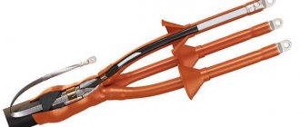
High voltage cable indicator 10kV
The high voltage cable indicator IVNK-10 is designed to determine the presence of high voltage 6-10 kV, 50 Hz, 3 phases on the conductors of a high-voltage cable, in complete switchgear (switchgear, switchgear, switchgear). The indicator consists of capacitive-type voltage sensors, indication elements and connecting wires for each phase. Sensors and indication elements are installed permanently.
The indicator does not require additional power sources. The flashing glow of the indication elements (gas-discharge or LED bulbs) is carried out due to the energy coming from capacitive-type sensors (a piece of high-voltage wire) attached to the cable cores. The presence of high voltage 6-10 kV, 50 Hz, 3 phases on the high-voltage cable cores, included distribution devices (KRU, KRUN, KSO).
The indicator can be supplied optionally with one of two types of indication elements: gas-discharge or LED lamps.
The indicators are supplied with red lamps, but can be ordered in three colors (yellow, green and red (ZhZK)).
If you need additional technical or commercial information, you can contact us by phone or write to us by e-mail.
equipment requirements
To ensure safety and reliability of operation, such devices must be certified. The requirements of the state standard take up no less than a page of text, let’s highlight the main ones:
- the insulating shell of the device must withstand voltages exceeding the measurement range;
- a single-pole indicator is manufactured in only one housing, eliminating the need to work with two hands;
- at one end of the pointer there is a probe for contact with the section of the circuit being tested, at the opposite end there is a contact pad for touching with the operator’s finger;
- a two-pole voltage indicator must consist of two housings with the same protection indicators, connected by a flexible insulated cable 1 meter long;
- the open section of the probe must not exceed the length specified for the selected measurement range;
- the light and (or) sound indicator of the presence of potential must be clearly visible under any measurement conditions.
Safety standards are uniform for the entire territory of the Russian Federation. No entity, be it Moscow or any regional center, has the right to soften the requirements for the production or use of such equipment.
Let's look at the operation of the main types of voltage indicators.
Double pole design
A high voltage indicator with two measuring contacts works on the principle of detecting the passage of current through a section of the circuit. An internal circuit compares the potential difference between the measuring point and ground (or neutral contact). If the response threshold exceeds the set value, an indication is triggered.
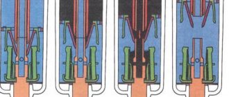
The design may be different, depending on the purpose: indication only, search for breakdown, measurement of the exact voltage value, setting the range (220 V, 380 V). As an example, the illustration shows an electrical circuit of a device that determines the presence of a phase in the measured area and an approximate voltage threshold.
There are no complex integral elements, so this indicator is reliable and trouble-free under any operating conditions. If measurements are taken outdoors, in bright light - parallel to the light indicator (in this case, an LED element), a sound is added.
By adding a voltage measurement module to the measuring circuit, we get a single-mode multimeter designed for safe high voltage measurements.
This is interesting: A regular multimeter can also be used as a high voltage indicator. However, it will take time to get ready (setting the appropriate measurement mode). And with safety, not everything is so smooth: specialized devices undergo strict certification.
Using such a device is not difficult: the passive contact on the connecting wire is applied to the ground (zero) bus of the electrical installation. Then the measuring contact must touch the potential measurement point.
Advantages:
- high measurement accuracy, functionality can be expanded if necessary;
- ability to work with high voltage without additional operator protection equipment;
- operator protection is ensured: there is no direct contact with open areas of the body.
Flaws:
- higher cost;
- The meter is quite bulky.
Rules of application
Before using the device, it is recommended to check the contents. Using the example of UVNU - 10SZ IP, the tube, insulation, and handle are inspected. The nodes must be securely connected; screw fastenings are used. A holder is fixed to the phasing tube. The ring stop must be attached to the body.
You might be interested in this Features of devices for measuring battery capacity
Important! External inspection is necessary in order to identify cracks or peeling.
Pointer Defects
Any defects in the pointer indicate that it is not ready for use. If drops of water or dirt are found on the ring or tube, they must be removed. For this purpose, it is better to use a napkin. The device should be stored in a dry place, preferably protected from ultraviolet exposure.
Particular attention is paid to the hook-shaped probe. It must be examined without gloves and touched. The indicator that the device is on should light intermittently. If you hear sound, it means the device is working properly. In this way, the skin resistance is assessed and the test is completed.
If the pointer does not respond to human touch, you can try moistening your fingers a little. At sub-zero temperatures, devices operate with a large error. It is especially problematic to carry out work at temperatures of −20 degrees or more. It is recommended to select a guaranteed voltage source for the test. The presented indicator records readings from 100 to 1000 volts.
Voltage source
Important! You must hold the handle during the test.
When the probe is brought in, it must come into contact with the core. Under normal conditions, a person will hear an intermittent beep. The light will blink. This confirms that the object is energized. The contact method is necessary to determine the phase.
When using signs, the electrician often has to stand on supports. It's good to have an insulating rod. When working with high-voltage equipment, it is better to use workpieces at least 6 m long. The head is necessary for grounding. Touching live parts is sometimes accompanied by a bright light and a powerful sound signal.
Live parts
Before checking the grounding in the installation, measure the voltage. The permissible level of energy flow is 1.5 kV. If the indication does not respond, you must touch the indicator with your non-gloved hand. When the cable is under induced voltage, the indication operates in constant mode. Sometimes it is necessary to determine the phase, then a working tube is used. It connects to the pointer, as well as the pin.
To make the connection, the shunt is inserted into the hole. There are marks on the indicator; you should not make significant physical efforts. A separate issue concerns operational activities related to testing. The rules are specified in the electrical installation instructions.
You may be interested in this. Features of the multimeter
Electrical installations
Test objectives:
- determining the minimum level of indicator activation,
- longitudinal insulation test,
- maximum threshold test
For testing, the pointer is suspended indoors on a hill. The contact probe should be at the bottom. First of all, a slight voltage is applied to the hook; it is important to monitor the light bulb. The maximum limit of the presented modification is 1.5 kW. The longitudinal insulation test allows you to determine the permissible voltage level.
Longitudinal insulation test
Important! The device in good condition can withstand a load of 12 kV.
In this case, the voltage supply time is important. The phasing tube is checked in a similar way. For this purpose, a conductive part with a voltage of 12 kV is supplied. However, when the phase is turned on oppositely, the parameter is different. It all depends on the resistance of the conductor.
An indication with a tube attached to the pointer is triggered at a load of 1.5 kV. Using the example of UVNsTF 10I, it can be seen that simple options with a phasing tube are easier to use. The model is suitable for testing cable and overhead lines. When testing electrical installations, it is important to check the serviceability of transformers.
Transformers test
The permissible operating voltage must be in the range of 6-10 kV. The indicator phasing tube can only be used in an alternating current circuit. The permissible frequency is from 50 megahertz. As the manufacturer indicates, the maximum load level is 15 kV. When using the model, contact tips and electrical circuit elements are connected.
Interesting! The indicator has two connecting wires, as well as insulation.
The rod is installed between the bushings, fastening occurs due to a threaded connection. The presented model has a three-digit display and uses LED bulbs. When voltage is applied to the hook, they light up. It also triggers if testing is performed.
The indicator is capable of functioning in self-monitoring mode. In this case, the circuit checks the health of the nodes and reports possible errors. When the device is switched to operating mode, it becomes possible to automatically determine the type of voltage. Contact with the current-carrying conductor is ensured by the tip. Determining polarity does not take much time.
Interesting! The “-” LED is activated when a negative voltage is detected in the current-carrying part. A decrease in frequency is accompanied by flickering of the light bulb.
Flickering on the indicator
Single pole design
Electric current flows between the phase (measuring point) and the ground loop, which is provided by the human body (operator). Inside the device there is a simple electrical circuit consisting of a neon lamp and a resistor. The resistance is selected in such a way that the electric current does not exceed a value safe for humans.
At the same time, the current strength must ensure reliable operation of the indicator. For a neon lamp, a few hundredths of milliamps are enough, so that the circuit operates stably.
How to use such a pointer? The device is held in one hand, the finger is placed on the back contact. After which the measuring probe is applied to the live part of the electrical installation. If there is potential, the warning lamp lights up.
Interestingly, various "advanced" transistor and LED circuits are not as reliable as a simple neon lamp and graphite resistor. The high percentage of false positives does not allow using such a device for professional purposes.
Advantages:
- cheapness of the device;
- efficiency of use;
- ability to work with one hand.
Flaws:
- low accuracy and reliability;
- no advanced functionality;
- potentially dangerous: there is contact of open areas of the body with the measuring part of the device.
Non-contact voltage indicator
If you have direct access to open contacts of electrical wiring or electrical installations, measuring voltage is easy. How to determine the potential (at least its presence) in hidden wiring?
For this purpose, there are non-contact indicators (not to be confused with current clamps).
Such indicators do not work directly with electric current, but with the electromagnetic field that arises around the conductor. In fact, it is a coreless transformer, or inductor.
The simplest pointers respond to an alternating magnetic field. When it is detected, a circuit assembled on triggers is activated, and voltage is supplied to the indicator (LED element). To enhance the detection effect, a sound signal is turned on in parallel.
Of course, there can be no talk of any voltage measurements. Moreover, the presence of an electromagnetic field depends on many factors, including the presence of a grounding bus next to the conductor. In other words, a well-laid electrical cable (according to the requirements of the PUE) will not be detected by a contactless probe.
Important: Such a pointer cannot be used as a hidden wiring detector; the detection distance is 1-2 cm in the open air.
Advantages:
- ease of use: no need to look for open contacts;
- safety: no contact with live parts.
Flaws:
- in reality, the device does not guarantee even 50% of the result.
Based on the principle of operation of such a pointer, the stronger the current in the cable, the higher the probability of detecting potential. Accordingly, if the electrical appliance is not turned on, its power cable will not actively form an electromagnetic field around itself. In this case, potential is present on the phase wire, and the danger of electric shock remains.
Important: If you plan to use such a sign, you should still check the absence of voltage in open areas with a conventional contact device before starting work.
Before using any measuring instrument, ensure that it has a safety certificate.
Operating principle
The operating principle is based on tracking circuit pulses. Current is supplied to the probe and applied to the contact. The indicator part monitors the voltage level and sends a signal to the control board. The models use an insulating part to ensure safety during operation.
Pointer Operation
The probe or tip can be connected to a flexible wire or tube. When the voltage exceeds the permissible limits, the indicator may not respond. There are models with and without a screen. Simple options are used with LED lamps.
Where can I buy
To purchase a voltage indicator as quickly as possible, you can visit your nearest specialty store. The optimal option, in terms of price-quality ratio, remains purchasing from the AliExpress online store. Mandatory long waits for parcels from China are a thing of the past, because now many goods are in intermediate warehouses in destination countries: for example, when ordering, you can select the “Delivery from the Russian Federation” option:
| 3 in 1 Digital Multimeter Voltage Indicator Tester Voltmeter | Voltage tester, waterproof | Screwdriver with voltage tester |
| Multi-digit test pencil AC DC 12-250V | VD700 High Precision Digital LCD Tester | Tester pencil, screwdriver 100-500V |