Regulations
Figure 12 1 Dots connected by a dashed line to a connector indicate connections to the corresponding pins of that connector. Single-pole, multi-position switch with a moving contact that closes three circuits, excluding one intermediate circuit 5.
Figure 15 5. Types and types of electrical circuits Before talking about the symbols on the circuits, you need to understand what types and types of circuits there are.
With the spaced method of depicting identical device elements, the contact pin designations are indicated on each component of the device element.
If it is necessary to indicate the limitation of the movement of the switch drive, a position diagram is used, for example, 1 drive provides a transition from position 1 to position 4 and back; 2 drive provides a transition from position 1 to position 4 and then to position 1; reverse movement is only possible from position 3 to position 1 2. Figure 3 5.
In a single-line drawing, circuits that perform identical functions are depicted with one line, and identical elements of these circuits are represented with one symbol. It is allowed to depict input and output elements according to the rules established in 5.
When executing a diagram in a line-by-line manner, it is possible to number the lines with Arabic numerals, see.
If necessary, the diagram indicates electrical circuits in accordance with GOST 2. Graphic symbols of radioelements
In the cabin
The main element of the automatic transmission with which the car owner interacts is the automatic transmission selector. It is used to switch transmission modes, and you should know the symbols on the automatic transmission in order to select the correct mode and understand exactly how the automatic transmission works at the moment. Mode designations are often duplicated on the dashboard of modern cars.
A typical selector with notation:
Let's look at the main symbols on the automatic transmission
Latin letter P: this is the beginning of the word Parking, indicating the parking/parking mode, which some car owners also call the parking brake.
In this mode, the vehicle's drive wheels are locked to prevent unintentional movement.
The letter R. The word Reverse begins with it, meaning movement in the opposite direction.
Selecting R on the selector engages the reverse gear of the box.
The letter N is a classic one, familiar to many from a manual “neutral” transmission.
In this mode, no force is transmitted to the wheels, but they themselves are not blocked.
This is the so-called Drive, the main mode of the box, in which normal movement is carried out.
Letter A.
Sometimes you see this designation instead of D, and it means the same thing - normal movement mode.
Designation on the automatic transmission L.
It indicates the engagement of a low gear (Low), which is useful for overcoming obstacles on the road. The engine braking function is activated to help the driver safely navigate steep descents.
- Digit 2: selecting this mode limits the maximum possible gear to the 2nd transmission stage.
- Number 3: a similar limitation, but the “ceiling” of gears is the third.
The letter M. This is an abbreviation for the word Manual, it is found on Tiptronic automatic transmissions and analogues equipped with the ability to switch to the so-called manual mode.
It allows the driver to manually change the gear ratio by moving the selector to a special section marked with “+” and “-” signs. Examples of such a box:
S – sport mode, characterized by a slightly optimized logic for changing transmission stages for fast movement.
Abbreviation OD.
This is the designation of an automatic transmission with an Overdrive, or “accelerated” mode.
W – winter, “Winter”, driving mode.
In it, the car starts moving from second gear to avoid slipping on snow and ice.
- E – fuel saving mode, Economy.
- The Hold button can have different meanings, usually it indicates a “winter” mode, similar to the W button.
It is mounted on the gearshift lever or placed on the dashboard:
On the automatic transmission lever there may be a designation of the type of gearbox installed in the car - for example, DSG, and the type of drive:
Next to the selector, additional function keys can be located that use various features of the car - opening the trunk, heated seats, etc. All of them are indicated by corresponding pictograms.
Species and types
Electrical wiring diagrams are special drawings that indicate certain connections between electrical elements and devices that are connected to the network and consume electricity. The connection is described and organized according to standards and rules that are defined and operate according to physical laws. The diagram is designed to teach electricians and other specialists to understand the principle of network structure and the structure of devices, what parts it consists of.
Example of an electrical installation drawing
Important! The main purpose of electrical diagrams is to help install and configure electrical devices and make repairs based on quick and easy troubleshooting. To delve deeper into the topic, you should understand what types of wiring diagrams exist and by what principles they are divided, what are their characteristic features
Electrical circuits, like documents, are divided into several types and types, divided according to certain standards. First of all, you need to understand the main types of electrical circuits, which are:
To delve deeper into the topic, you should understand what types of wiring diagrams exist and by what principles they are divided, what their characteristic features are. Electrical circuits, like documents, are divided into several types and types, divided according to certain standards. First of all, you need to understand the main types of electrical circuits, which are:
- Structural. The simplest option, which in the simplest “words” makes it clear how this or that device works and what it consists of. The order of reading such documents is indicated by arrows from block to block, and incomprehensible points are indicated by explanatory inscriptions;
- Assembly. They are often used in manuals or online resources, where it is suggested that you install electrical wiring or other elements yourself. In such a diagram, you need to show the exact location of each individual element of the circuit (sockets in the house, and so on);
Structure document
- United. As the name implies, this document combines several types and types of schemes. Typically, such electrical circuits are used in cases where all the important features of the circuit can be shown without a huge number of different elements;
- Layout diagrams. Documents defining the relative location of certain components of a product or electrical installation, and, if necessary, also bundles (wires, cables), pipelines, optical fibers, etc.;
- Are common. Those that define the parts that make up the complex, as well as their connections;
- Functional. They are not much different from structural ones, but they describe in more detail all the components and nodes of the network. They no longer have obvious connections and components;
Schematic drawing
- Principled. They are most often used in distribution networks, as they provide an accurate understanding of how a particular electrical equipment operates. On this kind of diagrams, all functional blocks of the circuit and the types of connections between them must be indicated;
- Connections. Original documents indicating methods of external connections of the device to other networks and other devices.
You might be interested in Grounding an electrical panel
Complete schematic drawing
The specific feature of the schemes divides them into:
- Electrical. Documents showing the components of products powered by electrical energy;
- Gas. Papers that display the structure and main components of the gas system of any equipment, room, etc.;
- Hydraulic Documents showing the components of products and their structure, using the energy of compressed fluid for work;
Functional electrical diagram
- Division diagrams Design documents that determine the composition of the device, its components, their intended purpose and relationship;
- Pneumatic. Documents showing the components of products and their structure, using the energy of compressed gases for operation;
- Kinematic. Diagrams in which, using special symbolic drawings, the links of mechanisms and kinematic pairs are indicated for their kinematic analysis;
Wiring diagram in the apartment
- Combined. With their help, the main and auxiliary equipment of a device or circuit, their interconnection and automation tools that show the technical process are displayed;
- Vacuum. Schemes that allow you to describe devices whose action (and their components) are based on changing pressure and achieving a vacuum;
- Optical. They represent the process of changing light in an optical system.
Pneumatic schematic drawing
Tips and tricks
As you can see, the main modes on all automatic transmissions are almost the same. Considering that there are only two pedals (gas and brake), to start a trip, you need to start the engine in mode P, then press the brake pedal and move the gearbox lever to position D (forward movement) or R (reverse movement).
Then you can release the brake pedal, also lower the handbrake (if it was engaged) and smoothly press the gas pedal. At the same time, after starting to move, it is important to remember that automatic transmissions often have a rather weakly expressed effect of engine braking compared to manual transmissions, that is, you need to use the brakes more actively.
To switch the main automatic transmission modes, you must hold down the brake pedal. If the brake is not pressed, the lever locks, which protects against accidental activation. Also, on the lever of many automatic transmissions there is additionally a separate button that must be pressed to turn on individual modes (for example, D2, L1, etc.)
After stopping (for example, at a traffic light), on most automatic machines there is no need to switch the gearbox from mode D to mode N. It is enough to hold the car with the brake pedal. At the same time, you need to remember that if you release the brake and do not press the gas, the car will still begin to move slowly forward on a flat road (similar to a manual transmission with first gear engaged at idle).
We also recommend reading the article on how to drive a car with an automatic transmission for beginners step by step. From this article you will learn about the features of driving a car with an automatic transmission, as well as where to start when interacting with an automatic transmission.
After the trip is over, you should stop the car, keep the brake pedal depressed, move the lever from position D to position P, then tighten the handbrake and then turn off the engine. In winter, you don’t have to use the handbrake (since a separate lock is activated in P mode), but in this case you need to park the car on a level surface.
Finally, we note that when driving a car with an automatic transmission, you should avoid sudden starts, slipping, and towing a trailer and other cars. It is also not recommended to try to push start a car with an automatic transmission, or to tow a car with an automatic transmission over long distances at high speed in the event of a malfunction without hanging the drive wheels.
While still on the move, you should not engage in lower gears if the speed is high and clearly does not correspond to the selected mode. Remember, ignoring these rules often causes serious automatic transmission breakdowns or complete failure of an expensive automatic transmission.
Circuit breaker: characteristics
Automatic machines can have different time-current characteristics:
a) current dependent; b) independent of current; c) two-stage; d) three-stage.
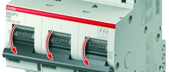
On the bodies of most machines you can see capital Latin letters B, C, D. The marking of circuit breakers B, C, D indicates a characteristic that reflects the dependence of the operation time of the machine on the ratio K = I/Inom.
- B - thermal protection is triggered after 4-5 s when the nominal value is exceeded by 3 times, and electromagnetic protection - after 0.015 s. The devices are designed for loads with low inrush currents, in particular for lighting.
- C is the most common characteristic of circuit breakers protecting electrical installations with moderate inrush currents.
- D - circuit breakers for loads with high starting currents.
The peculiarity of the time-current characteristic is that with the same ratings of machines of types B, C and D, their shutdowns will occur at different current levels.
Explanation of markings
When purchasing a modular security device, you should evaluate not only the brand and appearance. The characteristics of the machine play an important role. To do this, you need to understand the information that the marking of circuit breakers carries. It includes:
- brand;
- model;
- vendor code;
- current limiting class;
- trip current;
- time-current characteristic;
- rated current and voltage;
- connection diagram.
Brand, model and current characteristics
The marking begins with the name of the manufacturer, which is applied to the upper part of the case. The most famous are Schneider Electric, ABB, Hager and IEK. They have long remained leaders in sales on the market, as they produce high quality products.
The linear series of a switch often means the series of the device in the manufacturer’s line; it is represented by numbers and letters. For example, SH200 is a series of devices from ABB, and Acti9 is represented by Schneider Electric.
Based on the model, you can determine the price and technical characteristics. The S200, for example, is rated for faults up to 6 kA and is more expensive than the SH200 model (up to 4.5 kA).
There are five types of time-current properties of a switch, they are written in Latin letters B, C, D, K and Z. The first 3 characteristics are widespread. In cases of heavy load and active use of electronics, “K” and “Z” are needed.
The most suitable characteristic for protecting wiring in the home is C. Narrow-profile switches of types B and D are rarely installed, mainly on request.
Rated current and voltage
The number following the letters means the rating of the switch - this is the maximum passing current at which the machine does not turn off. It is indicated for t +30 C. For example, a device with a rated current of 15 A will withstand such a load up to 30 C, but if t rises higher, the device will operate at a lower current.
When the network is overloaded, when the current exceeds the rated current by 15-50%, the thermal release of the device is triggered.
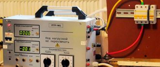
When a short circuit occurs, an overcurrent appears in the network and the machine is triggered in 0.015 s. If the machine is faulty, the insulation may begin to melt , which can lead to fire.
Under the time-current characteristic in Volts, the voltage (AC/DC) with a nominal value is indicated. This indicator determines the type of network in which the machine can be used. For example, 230/400 V means that the voltage of a three-phase network is 400 V, and a single-phase network is 230 V.
Tripping current and current limiting class
The maximum short-circuit current that passes through the device and does not damage it is called the rated breaking current. The current limit values for modular switches are 4500 A, 6000 A and 1000 A.
Below is the current limiting class. Overcurrents are dangerous due to the release of energy, which leads to melting of the wiring. The switch trips when the short-circuit current is maximum. But to reach this maximum, time must pass. The larger it is, the greater the damage caused to equipment and wiring.
The current limiter speeds up the time it takes to turn off the circuit breaker; this does not allow the short circuit current to reach its peak. Current limiting classes are plotted in a square. The higher the number, the sooner the switch will operate:
- The limit for the first class is more than 10 ms. With this class there are no markings on the machine body.
- Second class time - from 6 ms to 10 ms.
- The third class works the fastest - 2−6 ms.
Connection and article number
It happens that in production, the marking of machines includes a connection diagram. It consists of a circuit, releases and contacts.
Markings 1 and 2 on single-pole switches indicate top and bottom contact. The supply wire is connected to 1, the load is connected to 2. On two-pole machines, the numbers 1/3 mean the upper contact, 2/4 the lower.
Also near the diagram there is sometimes a marking N , indicating the terminal to which the neutral conductor should be connected. This designation is important in the case where there is no release.
The article number will help you find any switch model in the outlet catalog. Such information can be printed on different sides of the device.
The marking of electrical machines will help you choose the most suitable device for your living space. However, it is worth considering not only the technical characteristics, but also the operational features of the machine. After all, understanding the operating conditions will not only prevent breakdowns, but will also increase the safety of working with electrical appliances in the house.
What symbols are located on the body?
The markings applied to the body of each device include a set of numbers, diagrams, letters, and special symbols. The markings are made with indelible paint and are on the visible part. This is required for accessibility during operation after installation on a distribution panel with connected wires.
Circuit breaker model
Important! To check the markings, you do not need to remove the devices from the DIN rail and disconnect them. Each manufacturer uses its own designations
Most specialists in their work are faced with the type of arrangement of signs on household modular machines, which can be understood by deciphering the symbols and signs
Each manufacturer uses its own designations. Most specialists in their work are faced with the type of arrangement of signs on household modular machines, which can be understood by deciphering the symbols and signs.
Regardless of the company where the device was manufactured, the same data is applied to the case:
- manufacturer's name printed at the very top;
- indication of the model (series) with letters and numbers of the device series in accordance with the manufacturer’s data;
- rated current, shutdown characteristic, designated by the letter of the Latin alphabet “B”, “C”, “D”, “K”, “Z”;
- data on the rated voltage, showing the maximum value passing through the machine without switching off at an ambient temperature of 30 ° C, at which a kind of shield is formed for increased load;
- indicators of the rated breaking capacity that each electrical machine has;
- parameters of the current limiting class of the circuit breaker;
- panel information about the switching diagram.
Order of symbols on the outer panel of the device
Note! Manufacturers specify parameters without fail. There are some indicators in the general list, taking into account the marking data of which is especially important for uninterrupted operation
What do the inscriptions on the switch mean?
Symbols, numbers, letters, diagrams are applied to technical plastic with special indelible paint. Even with older models they remain readable. It is assumed that the user or electrician, barely glancing at the machine, should quickly determine its current characteristics and voltage.
Manufacturer and model of the machine
The top line of the marking block is occupied by the brand name. A certain color is selected for printing, often bright, and sometimes even by the shade you can determine which manufacturer’s products are in front of you.
The color of the inscription is usually repeated in the design of the control element - the lever with which the device is forcibly turned on or off. However, sometimes the handle is colored neutral gray or black
Experienced electricians suggest not to skimp when buying machines and to purchase devices only from proven European brands: Schrack Technik , Schneider Electric , ABB , Schaltbau , Moeller , HAGER , Legrand . There are several Russian brands that you can also safely trust: Elektrotechnik , TDM ELECTRIC , EKF .
The line below indicates the device model. All other inscriptions, except for the manufacturer's name, are usually printed in gray, so the series can be easily confused with technical specifications.
In order not to be mistaken, we look exactly at the second line. The line or model designation may look like this: BA63 , SH200 , Acti9 .
You can try to decipher the series, but the technical characteristics are not always hidden behind the letters and numbers; more often it is just the name of a specific model.
Models from the BA47-29 series have more than two hundred types, and they are not tied to certain rated currents - they can be 0.5 A, 5 A, or 63 A
The line designation can be printed either on a general gray background or on a colored line, which is located directly under the brand.
Determination of time-current characteristic
The next line is a combination of a Latin letter and a number. The first letter indicates the time-current characteristic. It refers to how quickly a switch operates when a certain amount of current flows through it. There are five different types in total: “B”, “C”, “D”, “K”, “Z”, but in everyday life machines B, C, D are used.
The dependence of quantities is often presented in the form of graphs that can be found on the Internet. They look like this:
The graph shows how the operating speed of the machine depends on the multiple of the effective current to its rated value. Calculations follow the formula k=I/In (+)
Thus, if the value of k is between 3 and 5 - this is category B, between 5 and 10 - C, between 10 and 20 - D.
An example of the VTX designation on the device body. In combination “B16” V is the time-current characteristic, and 16 is the rated current
If you take two switches with the same rated current value, but with different tripping properties, they will also react differently. For comparison, consider C16 and B16. If we use the formula, then as a result we will get for C16 - 80-160 A, and for B16 - 46-80 A.
What does this look like in practice? Suppose the current sharply increases to 100 A. B16 will turn off instantly, since 80 A is enough for it, and for C16 to work, it takes some time for the plate to heat up. Then the thermal protection begins to operate and the machine turns off. The time difference usually takes a fraction of a second.
Rated current and its designation
The number to the right of the Latin letter (BTX) indicates the denomination of the machine. The rated current indicates at what maximum value the machine will be in the operating state, that is, the current will freely pass through it without emergency shutdown.
An important point: the specified data is relevant only at a certain temperature, namely +30ºС. If the temperature is higher, the switch may operate at a lower current value.
The specified rating is 32A. Therefore, under favorable conditions, the machine will not turn off until the current exceeds this value. But if the temperature rises, it can work at 25...30A
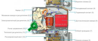
Let's look at what happens inside the device during a trigger. The machine is turned off thanks to the operation of two types of circuit releases - thermal and magnetic.
The first one comes into operation if there is an overload in the electrical network. A current value higher than the rated one heats up the bimetallic plate, it bends and breaks the circuit - the machine turns off. It is estimated that the load current must exceed the nominal by 15-55% for a break to occur.
But in addition to overload in the network, there is also such a phenomenon as overcurrent. The reason for its appearance is a short circuit. It is no longer the thermal, but the electromagnetic release that reacts to overcurrents.
If the device is in working condition, the response occurs instantly, within a maximum of 0.02 seconds. A delay in emergency shutdown leads to failure of the wires. First, the insulating layer melts, then a fire may occur.
To protect wiring and your own life from overloads and short circuits, it is recommended to purchase only high-quality protection devices.
Rated voltage and frequency markings
The line below indicates the value of the rated voltage. It must also be observed when choosing a device without fail. Marking can be determined by units of measurement - Volts, which are designated by the letters V or V. For accuracy, the following symbols are also used: “-” - constant voltage, “~” - alternating.
Option for designating the rated voltage. If two numbers are indicated, then the device can be used to protect 1-phase and 3-phase networks: 230V – for single-phase, 400V – for three-phase
The frequency is determined in Hertz and is designated as 50 Hz. But it may not be detected on the case, because almost all household appliances operate in the same mode.
If you need to know exactly some characteristics of the machine, but their designations are not on the panel, you should look at the instructions, which list all the technical data about the device.
Trip current limit
The next value indicated on the body of the machine is the shutdown current, which is otherwise called the breaking capacity of the device.
If a short circuit suddenly occurs and an overcurrent appears in the circuit, the machine will operate in emergency mode, but at the same time fully retain its functionality. You can see that the shutdown current is several times higher than the nominal value.
It is also possible that the overcurrent value will be higher than that indicated on the machine. Then there is no guarantee that the device will work correctly and will not be damaged. Most likely, the magnetic release simply cannot cope with the load.
An example of the designation of the shutdown current - the number 4500 in a black frame, is located directly under the voltage and frequency values. On some models this parameter is not specified
In addition to the value of 4500 A, which is typical for many household-class machines, you can find 6000 A and 10000 A.
What is current limiting class
Immediately below the tripping current limit is the current limiting class. It is easy to find on the panel - it is the number 1,2 or 3, enclosed in a black square. During a short circuit and overcurrent appears in the network, the system may suffer.
The faster the machine operates, the sooner the effect of thermal energy, which is a consequence of the occurrence of overcurrent, will cease, and the sooner stability will occur.
Thus, the current limiting class shows the time interval to which the machine can limit the short circuit time.
Under the number 6000, the current limiting class is clearly visible - 3. If there is no marking (and this occurs on many models), then its value is 1
Class divisions:
- Class 1 – limitation > 10 ms;
- 2nd class – from 6 to 10 ms;
- Grade 3 – from 2.5 to 6 ms.
The third class is the “fastest” and preferable when choosing an automatic machine.
Wiring diagram
On some circuit breakers, in addition to the main characteristics, you can find a connection diagram. It is usually located on the right side of the front panel.
The diagram shows an electrical circuit with symbols, including releases and contacts to which the wiring is connected. Numbers are used to indicate contacts
The circuits on 1-pole and 2-pole devices are different. On the second, in addition to the circuit with contacts, there are terminal markings, and also on some models the N icon, indicating the connection of the neutral wire.
Classification of devices
According to the drawn up diagram, electrical devices are selected. They must meet the technical requirements for a specific type of product. According to GOST R 50030.2-99, all automatic protective equipment is classified into several types according to the type of design, environment of use and maintenance. In this case, the unified standard refers to the use of GOST R 50030.2-99 in conjunction with IEC 60947-1. GOST is applicable for switching circuits with voltages up to 1000 V AC and 1500 V DC. Circuit breakers are classified into the following types:
- with built-in fuses;
- current-limiting;
- stationary, plug-in and retractable versions;
- air, vacuum, gas;
- in a plastic case, in a shell, open design;
- emergency switch;
- with locking;
- with current releases;
- serviced and unattended;
- with dependent and independent manual control;
- with dependent and independent control from the power source;
- switch with energy storage.
Automatic switches IEK series VA47-100
Circuit breakers of the BA 47-100 series are designed to protect circuits that contain not only active, but also inductive loads. Moreover, protection can be performed for individual and group consumers. Features of circuit breakers of the BA 47 - 100 series are:
- • galvanic coating of contacts,
- • the presence of a special indicator indicating the position of the contacts,
- • load connection can be made to the upper or lower jaws,
- • the latch on the DIN rail has a special lock.
Graphic designation of electrical power facilities on diagrams
Graphic symbols Each type of graphic document has its own symbols, regulated by relevant regulatory documents. In order to understand in the diagram what type of switch we are talking about, this must be remembered.
Some light source control devices are not labeled, such as push-button devices and dimmers. Letter designations of elements in the diagrams: basic and additional The table above shows international designations.
The latest GOST, which came out, has been supplemented with many new designations, current today with code 2. Most of the designations are graphic. This will be the complete schematic diagram.
They are usually a single line diagram labeled with RCDs, circuit breakers, contactors and other protective equipment. D - Grounding symbol. Let's consider the design information from the point of view of an amateur electrician who wants to change the wiring in the house with his own hands or draw up a drawing for connecting the dacha to electrical communications. It should be noted that more often in home practice, only three types of electrical circuits are used: Mounting - for the device, a printed circuit board is depicted with the arrangement of elements with a clear indication of the location, rating, principle of fastening and connection to other parts.
Paired checkmarks when depicting sockets indicate the number of wires. Currently, the population and the trading network are using a significant number of various electronic instruments and devices, radio and television equipment, which are manufactured by foreign companies and various joint-stock companies. All information is presented in blocks with captions - names of devices.
How switches, switches, sockets are depicted There are no images approved by standards for some types of this equipment. Next to the letter designation of an element there is often its serial number. Types and types. A pulse relay is also quite easy to distinguish by the characteristic shape of the sign. The type and number are a mandatory part of the alphanumeric designation and must be assigned to all elements and devices of the object.
Regulations
But all other types of switches have their own symbols in electrical diagrams. There are separate designations for two-key and three-key switches.
For example, lamps with incandescent lamps are depicted in the form of a circle, with long linear fluorescent lamps - a long narrow rectangle. B is an electricity icon representing alternating voltage. A characteristic feature of this scheme is minimal detail. You need to look closely at all these little things and remember them. It consists of devices that convert non-electrical quantities into electrical ones, which does not include generators and power supplies. Conventional graphic symbols of radioelements
Marking of circuit breakers: designation and inscriptions
The markings of circuit breakers should not be erased over time. Therefore, symbols, letters, inscriptions and numbers are applied to the body with special indelible paint. The marking is located on the front panel of the device. This is done so that when the device is in working order, you do not have to dismantle the device in order to find out the required characteristics.
Marking of the machine
Marking includes such indicators as:
- company manufacturer;
- rated current;
- voltage; frequency;
- trip current; model;
- current limiting class;
- connection diagram;
- terminal designation;
- vendor code.
Marking data is additionally duplicated in the technical data sheet of the device.
Marking of circuit breakers: symbols and inscriptions
Rated current
This characteristic is indicated in the form of numbers and is plotted next to the time-current characteristic. Manufacturers produce five types of automatic machines: B, C, D, K, Z. The most popular are B, C, D. For domestic conditions, automatic machines with a temporary current characteristic of type C are used.
The remaining types are intended for a narrow profile. After this value, a number is applied indicating the rated current of the circuit breaker. It indicates the maximum current value at which the protective device is able to remain operational.
If this value is exceeded, the machine will operate. In this case, the rated current is calculated for a temperature regime that corresponds to + 30 degrees. Therefore, if the room temperature is higher than this indicator, the protective device may operate, even if the current strength was less than the specified one.
The operating principle is based on the protection of two releases - thermal and electromagnetic. In this case, the thermal release will de-energize the electrical circuit in the interval from several seconds to several minutes. Electromagnetic protection will work much faster - 0.01 - 0.02 seconds, otherwise the wiring will begin to melt, which may lead to a further fire.
Voltage and frequency
The rated voltage is located under the time-current characteristic. This standard can apply to direct and alternating current and is indicated in volts. In this case, direct current is denoted by “?”, and alternating current by “~”. Each value corresponds to a given electrical network.
Voltage is indicated in two designations: one for a single-phase electrical network, the second for a three-phase one. For example, marking in the form: 230/400V~ means that the machine is intended for an electrical network with one phase and a voltage of 230 volts, as well as for an electrical circuit with three phases and a voltage of 400 volts.
Trip current
This criterion indicates the short circuit current. In this case, the protective device will operate without compromising its functionality. The electrical line has a rather complex structure, in which increased current values sometimes appear due to a short circuit.
This is a short-term process, but the current is too high. Circuit breakers have the ability to trip when the current exceeds 4500A, 6000A or 10000A. Moreover, the higher this indicator, the greater the guarantee that the protective device will work even in the most severe emergency situation.
Manufacturer
At the very top of the circuit breaker the brand of the device is indicated. To achieve this, a brighter paint color is often chosen. Typically this color matches the color of the control lever. Sometimes a neutral gray color is chosen for this.
Current limiting class
The number after the short-circuit current (3 or 2) is the current limiting class.
A circuit breaker with this function does not allow the short circuit current to reach its maximum value and trips at the earliest possible stage.
That is, this figure shows how quickly the electric arc is extinguished inside the device, preventing individual elements and parts from heating up to extreme temperatures and contributing to a fire.
Class '2'
limits short-circuit current within half a half-cycle
Class '3'
within 1/3 of a half cycle
Roughly speaking, an automatic machine with a “C” will cope with the consequences of a short-circuit current faster than with a “D”. In terms of time, this can be reflected in the following table.
Devices with “first” class are not marked in any way or with any numbers.
All of the above markings are located on the front side. Now let's move on to the side edge. There is also a lot of useful information there.
Why is labeling necessary?
For a qualified electrician, the front panel of the machine is like an open book - in a couple of minutes he can find out everything about the device, from the manufacturer to the rated current value. An experienced installer can easily distinguish between devices that are absolutely identical from the point of view of the average person.
A homeowner unfamiliar with the intricacies of electrical wiring can also understand the information provided by the manufacturer. Using special symbols located on the front panel, you can distinguish the machine from the RCD, find out its main technical characteristics and find out in what sequence the wires are connected.
Information about a separate circuit breaker may be required if:
- it is necessary to replace the device;
- a new machine should be installed due to the emergence of a new circuit;
- it is required to compare the rated current load of the line and the circuit breaker;
- you need to find the cause of the emergency shutdown, etc.
Some symbols become intuitive, while others require certain knowledge to decipher. If you are planning to replace the wiring yourself or connect another power circuit, it is better to study the information about the machines in advance.
Tips for choosing a circuit breaker
The machine is selected based on certain characteristics, many of which can be recognized by the markings on the front panel.
In addition to the analyzed characteristics, you should know other nuances of choice. For example, before purchasing a machine, be sure to calculate its power and select the required number of poles.
More information about the calculation and selection of a circuit breaker is written in this article.
The brand is important, as is the condition of the wiring.
Correct Conductor Identification
As I already wrote above, we take the latest GOST 33542–2015 officially implemented in Armenia, Belarus, Kyrgyzstan, Moldova, Russia and Tajikistan, then we find table A.1 there, which clearly regulates the colors, alphanumeric and graphic designations used for identification conductors and terminals of electrical equipment. And we use it!
Table A.1. Start. GOST 33542–2015
End of table A1 GOST 33542–2015
About IEC 60445:2017
This standard was released in August 2021 and replaced IEC 60445:2010, on the basis of which, as we know, GOST 33542-2015 was created. This standard has extremely important changes compared to IEC 60445:2010:
- the positive pole conductor is prescribed to be marked in red;
- negative pole conductor – white;
- functional grounding conductor – pink;
- Amendment 1, in particular, corrected two letter color designations in Table A.1. For brown color, the designation "BR" is replaced by the correct designation "BN", for gray color the designation "GR" is replaced by the designation "GY".
According to GOST 33542, the positive pole conductor is designated in brown, and the negative pole conductor is marked in gray.
Therefore, it is better to take this into account now. And the GOST 33542-2015 standard will be revised over time and brought into compliance with IEC 60445:2017.
AC electrical circuits
For example, we will determine what color the insulation of conductors in the electrical wiring of individual residential buildings and apartments should be.
We know that in three-phase electrical installations of buildings with TN-CS and TT system grounding types, 5 conductors are used: L1, L2, L3, N, PE. And if the electrical installation is single-phase, then 3 types of conductors are used: L, N, PE. These conductors should be marked with strictly defined colors.
In three-phase electrical installations in buildings, most electrical circuits are single-phase. The color of the insulation of the phase conductor of a single-phase electrical circuit must match the color of the insulation of the phase conductor of the three-phase electrical circuit to which it is connected.
For the phase conductor of a single-phase electrical circuit of a single-phase building electrical installation, the preferred color is set to brown. Therefore, the insulation of phase conductors in single-phase electrical circuits of single-phase electrical installations in buildings should be brown.
According to the requirements of GOST 33542-2015, the neutral conductor should be identified in blue. Therefore, the insulation of neutral conductors in all electrical circuits of single-phase and three-phase electrical installations in buildings must be blue.
According to the requirements of GOST 33542-2015, the protective conductor should be identified by a combination of yellow and green colors. Therefore, the insulation of protective conductors in all electrical circuits of single-phase and three-phase electrical installations in buildings should be yellow-green.
Then, according to GOST 33542-2015, we obtain the following cheat sheets: for three-phase and single-phase electrical installations of buildings (AC electrical circuits):
It should be noted here that phasing is not implied by these colors (brown, black and gray). This means that you can, for example, mark conductor L1 not only with brown insulation, but also with gray or black.
DC electrical circuits
The colours, alphanumeric symbols and graphic symbols used to identify conductors and terminals of electrical equipment in DC electrical circuits will be as follows (using amendments to IEC 60445:2017)
:
| Conductors and terminals of specific types of electrical equipment | Identification of conductors and terminals of electrical equipment using | |||
| Alphanumeric designations | Colors | Graphic symbols | ||
| Conductors | conclusions | |||
| Positive pole conductor | L+ | + | Red (RD) | + |
| Negative pole conductor | L- | — | White color (WH) | — |
| Middle conductor | M | M | Blue (BU) | No recommendation |
| Protective conductor | P.E. | P.E. | Yellow-green (GNYE) |
As a result: you should buy the cable or wire that has the proper color identification of the cores in order to meet the requirements of modern GOST 33542-2015.
Also, for those who prefer not to read, but to watch, we have released a video for you below:
1.1. Letter designations (GOST 2.710-81).
Basic rules for drawing up circuit diagrams: Break the device into functional parts: power supply, final input devices and signal flow to the decision device, final output devices and signals to them from the decision device, decision device, data exchange with other equipment. It would be good if you can depict these parts on separate sheets. Movement of signals. schemes always! All signals with the same image and inscription are considered connected.
It is impossible to read all the normative literature related to your specialty or even a narrower specialization. Examples of UGO in functional diagrams Below is a drawing depicting the main components of automation systems.
Particular attention is paid to electrical circuit diagrams, which determine not only the basic electrical parameters, but also all the elements included in the device and the electrical connections between them. There are no standards-approved images for some types of this equipment.
The purchased components used or self-manufactured electrical electronic components are necessarily reflected in the circuit and installation electrical diagrams of devices, in drawings and other technical documentation, which are carried out in accordance with the requirements of ESKD standards. This is the first time this information has been published in such a volume.
There are no standards-approved images for some types of this equipment. The purchased components used or self-manufactured electrical electronic components are necessarily reflected in the circuit and installation electrical diagrams of devices, in drawings and other technical documentation, which are carried out in accordance with the requirements of ESKD standards. This is the first time this information has been published in such a volume.
We recommend: Energy passport what is it
Types and types of electrical circuits
C — Display of MI actuators. It is driven mechanically or electrically. Reading and drawing circuit diagrams is an essential part of being an industrial engineer. Power varies from 0.
Conventional graphic images based on GOST Power varies from 0.
I recommend
Designations of electromechanical devices and contact connections Examples of designations of magnetic starters, relays, as well as contacts of communication devices can be seen below. Conventional graphic images based on GOST Examples of UGO in functional diagrams Below is a drawing depicting the main components of automation systems.
Network connecting lines are shown in full, but according to the standards, they are allowed to be cut off if they interfere with the normal understanding of the circuit. Functional - here, without detailing the physical dimensions and other parameters, the main components of the device or circuit are indicated. Conventional graphic designation and letter code of elements of electrical circuits Name of circuit element Letter code Electrical machine. READING ELECTRICAL DIAGRAMS WITH A TRANSISTOR - PART 3
Features of releases
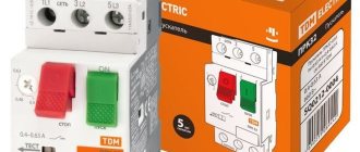
Manufacturers produce the following options:
- providing for manual shutdown - mechanical;
- triggered when an overload occurs - thermal;
- responding to the occurrence of a short circuit - electromagnetic.
Another separation option is the number of connection poles:
- used for use in a single-phase circuit - single-pole;
- when it is necessary to disconnect two poles at the same time, two-pole ones are installed;
- if necessary, simultaneously provide protection for a three-phase circuit or three single-phase columns - three-pole;
- in circuits with separation according to the principle of “star with a dedicated zero point” with separate protective and working zero - four-pole.
Machine body
When choosing a modular machine, pay attention to how the body itself is assembled. It is always a non-separable structure with rivets
So, when purchasing, it would not be superfluous to count the number of such rivets. On ordinary switches, there are usually at least 5 of them.
Although I often come across even with four.
However, there are models (for example from Schneider Electric, ABB and others) where there are six rivets!
What does this extra rivet do? When a circuit breaker trips due to a short circuit, an arc forms in the housing.
It's like a miniature explosion that is trying to tear apart the device from the inside. So, an additional rivet prevents the possibility of any change in the geometry of the device.
On 4 or 5 riveted ones, the switch may not break, but from several short circuits, the geometry and location of the internal components will change and they will move a couple of millimeters relative to their normal location. This will gradually lead to the device working poorly and at one point jamming.
In fact, all the mechanisms inside the circuit breaker seem to “hang” on the body. It's like the frame of a car.
Therefore, any change in geometry leads to the device stopping working normally. For example, it starts to buzz or hum.
As for the case, sometimes it doesn’t hurt to pay attention and compare their sizes. Some models of different brands and manufacturers, having the same rated current, differ slightly in size
For those where the body is several millimeters larger, the cooling will be better accordingly.
This is especially important when the machines are densely located in one row.
What is an automatic transmission
What is an automatic transmission - this is an abbreviated name for Automatic Gear Shift, it allows the driver not to change gear manually when the car picks up speed or reduces it, smart electronics does it for him, choosing the optimal moment to engage an upshift or the moment to engage a downshift, the driver remains just select the direction on the shift selector forward or backward and press the brake or gas pedal depending on the need, there is no clutch pedal with such a box, there is only gas and brake.
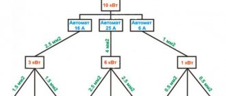
Selective connection of protective equipment
If a high load on the network is expected, the method of connecting several protection devices in series is used. For example, for a chain of four circuit breakers with a rated current of 10 A and one input device in the diagram, each circuit breaker with differential protection is graphically designated in series one after another with the device output to a common input device. What does this give in practice:
- compliance with the connection selectivity method;
- disconnecting only the emergency section of the circuit from the network;
- non-emergency lines continue to operate.
Thus, only one of the four devices is de-energized - the one that experienced a voltage overload or a short circuit.
An important condition for selective operation: that the rated current of the consumer (lamp, household appliance, electrical device, equipment) be less than the rated current of the machine on the supply side. Thanks to the sequential connection of protective equipment, it is possible to avoid fires in wiring, complete blackout of the power system and melting of wires
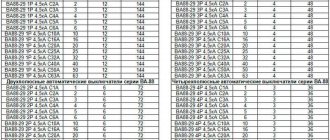
Automatic circuit breaker IEK series BA 88
Circuit breakers of the BA 88 series have proven themselves to be reliable devices and received a silver medal for reliability at the international exhibition "Electro" in 2006. The design of the BA 88 circuit breaker provides not only manual shutdown, but also two independent releases. Moreover, any of them can disconnect the network and are isolated from each other and from external influences. The body of the BA 88 machines has compact overall dimensions and is made of durable material. It is possible to connect additional devices. The operating voltage of VA 88 machines is 400 V. And the range of rated currents starts from 12.5A and ends at 1600A. This allows the machines of this series to be used not only in apartments, but also in any area of public utilities, as well as in industrial production areas.
Regulations
Figure 12 1 Dots connected by a dashed line to a connector indicate connections to the corresponding pins of that connector. Single-pole, multi-position switch with a moving contact that closes three circuits, excluding one intermediate circuit 5.
Figure 15 5. Types and types of electrical circuits Before talking about the symbols on the circuits, you need to understand what types and types of circuits there are.
With the spaced method of depicting identical device elements, the contact pin designations are indicated on each component of the device element.
If it is necessary to indicate the limitation of the movement of the switch drive, a position diagram is used, for example, 1 drive provides a transition from position 1 to position 4 and back; 2 drive provides a transition from position 1 to position 4 and then to position 1; reverse movement is only possible from position 3 to position 1 2. Figure 3 5.
In a single-line drawing, circuits that perform identical functions are depicted with one line, and identical elements of these circuits are represented with one symbol. It is allowed to depict input and output elements according to the rules established in 5.
When executing a diagram in a line-by-line manner, it is possible to number the lines with Arabic numerals, see.
If necessary, the diagram indicates electrical circuits in accordance with GOST 2. Graphic symbols of radioelements